Note: Descriptions are shown in the official language in which they were submitted.
WO 2007/008135 CA 02614564 2008-01-07PCT/SE2006/000781
1
FASTENING SPIDER AND METHOD OF FASTENING
Field of the Invention
The present invention relates to a fastening spider
for fastening a wear-resistant lining element to a sup-
port surface, over which wear-resistant lining element
material in the form of pieces or particles is intended
to move. The fastening spider comprises a mounting por-
tion for mounting positioning and clamping to the sup-
port surface' and at least one leg projecting from the
mounting portion and having an underside for holding the
wear-resistant lining element to the support surface. The
underside of the leg has an outer portion and an inner
portion, the inner portion being positioned closer to the
mounting portion than the outer portion.
The invention also relates to a wear lining and a
method of fastening a wear-resistant lining element to a
support surface, over which wear-resistant lining element
material in the form of pieces or particles is intended
to move.
Background Art
There are many different types of fastening means
for fastening wear-resistant lining elements to a support
surface for the purpose of protecting the support surface
from wear. This is common in handling materials such as
sand, gravel, stone, ore etc. which, with or without
water being added, cause significant wear on the surfaces
over which the material moves. For a long service life of
the surface, it is coated with wear-resistant lining ele-
ments of wear resistant material, such as elastomeric
material, some type of ceramic or a combination thereof.
The wear lining gives wear protection to, among other
things, chutes, drums, bins, feeders, feed hoppers,
transhipment places and vehicle platforms in the stone-
working, mining and installation industry. Due to the
WO 2007/008135 CA 02614564 2008-01-07 PCT/SE2006/000781
2
large number of different applications where wear linings
are used as wear protection, the wear linings are often
manufactured to allow adjustment and cutting to suit a
certain type and shape of surface. It is important that
the wear lining be well fastened to the support surface
so that it remains in place when subjected to vibrations,
shocks and impacts. In many cases it is also desirable to
be able to quickly exchange the wear lining as it starts
to be worn out.
A general drawback of existing fastening devices and
methods of fastening wear-resistant lining elements to
a surface is that they are relatively complicated and
expensive in terms of both construction and installation.
A further drawback is that the fastening devices do not
always effectively fasten the wear-resistant lining ele-
ments to the support surface, or that the fastening, when
mechanically affected, is not capable of holding the wear
lining in place. This results in production troubles on
the one hand since a loose wear lining must be fastened
again and, on the other hand, because they are damaged
more easily and thus must be replaced prematurely.
DE 43 15 421 discloses a fastening element for
fastening, for instance, wear-resistant lining elements
of elastomeric material to a surface. The element has the
shape of a four-armed cross with a central mounting por-
tion to fasten the fastening element to a surface using,
for instance, a bolted joint. The arms then help to hold
the wear lining which after mounting is clamped between
the arms and the support surface. The fastening element
is made in the form of a long steel section which is then
cut to provide fastening elements of the desired thick-
ness.
The problem in connection with this fastening ele-
ment is, among other things, that the wear-resisting lin-
ing element is not sufficiently effectively fastened to
the support surface. This results in operating troubles
WO 2007/008135 CA 02614564 2008-01-07PCT/SE2006/000781
3
and, thus, increased costs in the contexts where the ele-
ment is used.
EP 1 058 801 and the brochure "Trellex SQ Modul-
system" published by the Applicant in 2001 describe a
wear lining which is made of a number of juxtaposed wear-
resistant lining elements of elastomeric material. The
wear-resistant lining elements are in the form of panels
with two large faces and two connecting narrow faces and
are clamped to the support surface by a fastening means
in the form of bolts and washers. The wear-resistant lin-
ing elements have at the two opposite narrow faces V-
shaped recesses which are open towards the narrow faces.
The fastening means consist of washers with V-shaped
projections which are arranged in the V-shaped recesses
and abut against the recesses of the narrow faces after
clamping the washers by means of the bolts.
Although the wear lining according to EP 1 058 801
is a multipurpose lining and effective, it happens that
the wear-resistant lining elements do not sufficiently
effectively abut against the support surface. As mention-
ed above, this causes additional costs in the form of
stoppage and the necessary replacement of damaged wear-
resistant lining elements.
Summing up, the technicians have problems with
increased costs in the form of stoppage, the necessary
replacement of damaged wear-resistant lining elements,
increased wear etc. An important factor is here that
wear-resistant lining elements do not sufficiently effec-
tively abut against a support surface on which they are
mounted. A further problem is that increased noise occurs
as material moves over an insufficiently fastened wear-
resistant lining element.
Summary of the Invention
An object of the present invention is to provide an
improvement of the above techniques.
WO 2007/008135 CA 02614564 2008-01-07PCT/SE2006/000781
4
In particular, an object of the invention is to pro-
vide abutment of wear-resistant lining elements against a
surface, which is reliable, easy and inexpensive to main-
tain, has a simple construction and a low manufacturing
cost.
An object is also to provide a fastening device
which effectively fastens wear-resistant lining elements
to a support surface and which, when mechanically affect-
ed, is capable of holding the wear lining in place.
Another object is to provide reduced noise as mate-
rial in the form of pieces or particles moves over a
wear-resistant lining element.
To achieve these and other objects, there are pro-
vided according to the invention a fastening spider, a
wear lining and a method of fastening, having the fea-
tures defined in the main claims. Preferred embodiments
are stated in the subclaims.
According to a first alternative, a fastening spider
is thus provided for fastening a wear-resistant lining
element to a support surface, over which wear-resistant
lining element material in the form of pieces or par-
ticles is intended to move, comprising a mounting portion
for mounting positioning and clamping to the support sur-
face and at least one leg projecting from the mounting
portion and having an underside for holding the wear-
resistant lining element to the support surface, said
underside having an outer portion and an inner portion,
the inner portion being positioned closer to the mounting
portion than the outer portion. The outer portion is, at
least in the mounting positioning of the mounting por-
tion, positioned closer to the support surface than the
inner portion.
The expression "mounting positioning" refers in this
patent application to the position of the mounting por-
tion of the spider just before it is being fastened to
the support surface, for instance by means of a through
bolted joint or a welded bolt. If a bolted joint is used,
WO 2007/008135 CA 02614564 2008-01-07PCT/SE2006/000781
5
the bolt extends through a hole in the mounting portion
and also a hole in support surface, but the actual joint
is not tightened. By "clamping" is meant the state of
the mounting portion when, for instance, the bolted joint
is fully tightened. In brief, "mounting positioning" can
be illustrated, for instance, with the position of the
fastening spider when it is placed with its underside
against a horizontal flat support surface, with its
mounting portion immediately above the mounting point on
the support surface.
The difference in the positioning of the fastening
spider relative to the support surface in "mounting posi-
tioning" and "clamping" is thus essentially the distance
to the support surface along the normal direction of the
support surface. With a completely flat support surface,
the difference is the distance to the support surface
along the normal direction of the support surface.
A general advantage of the invention according to
this alternative is that it will be possible to make a
fastening spider of the above type which has a simple
construction and is easy and inexpensive to manufacture,
install and replace.
A special advantage is that the fastening spider
effectively holds wear-resistance lining elements to a
support surface. This is achieved by the above-described
shape distributing clamping force, via the mounting por-
tion, uniformly in the legs of the fastening spider. In
this way, the holding force of the spider legs against
the wear-resistant lining element will be greater in the
outer portions of the leg, compared with prior-art tech-
nique. Traditionally, a greater holding force occurs in
portions close to the mounting portion, for instance
because the spider legs tend to be bent in clamping of
the fastening spider, which is one of the effects that
are counteracted by the described invention.
It should be noted that that part of the wear-
resistant lining element which is clamped between a
WO 2007/008135 CA 02614564 2008-01-07 PCT/SE2006/000781
6
spider leg and a support surface is often made of an
elastomeric material which can partly yield to or be
depressed by forces applied. This also promotes the
effect and advantage that the force exerted by the
spider is more uniformly distributed in the legs of
the fastening spider.
Another advantage is reduced noise as material
in the form of pieces or particles moves over a wear-
resistant lining element which is fastened according
to the invention.
The fastening spider may, in the mounting position-
ing of the mounting portion, be arranged to be in contact
with the support surface or the wear-resistant lining
element, merely using the outer portion on the underside
of the leg.
The fastening spider may also, in the mounting posi-
tioning of the mounting portion, be arranged to be in
contact with the support surface or the wear-resistant
lining element, using the underside of the mounting por-
tion.
The fastening spider may, also when clamped to the
support surface, in combination or separately, have the
underside of the entire leg positioned at the same dis-
tance from the support surface, have merely the outer
portion on the underside of the leg in contact with the
support surface, and/or have the underside of the mount-
ing portion in contact with the support surface.
In one embodiment, the fastening spider may, after
being clamped to the support surface, be resilient, which
is an effect of the mounting portion not being in direct
contact with the support surface. It is also possible to
provide rigid fastening if the mounting portion is clamp-
ed so that it abuts rigidly against the support surface,
of.the wear-resistant lining element or a combination there-
The fastening spider may, also on the underside of
the leg, have at least one projecting supporting point
WO 2007/008135 CA 02614564 2008-01-07 PCT/SE2006/000781
7
directed towards the support surface. The supporting
point may in turn extend down into through holes in the
wear-resistant lining element, extend into recesses in
the wear-resistant lining element and/or be pressed into
the wear-resistant lining element.
The underside of the leg of the fastening spider may
also be arched in the form of an arch which, seen from
the position for mounting positioning, is convex from the
support surface.
According to a second alternative, a wear lining is
provided, over which material in the form of pieces or
particles is intended to move, comprising at least one
wear-resistant lining element fastened to a support sur-
face by means of at least one fastening spider, said
fastening spider having a mounting portion for mounting
positioning and clamping to the support surface and at
least one leg projecting from the mounting portion and
having an underside for holding the wear-resistant lining
element to the support surface, said underside having an
outer portion and an inner portion, the inner portion
being positioned closer to the mounting portion than the
outer portion. The outer portion is, at least in the
mounting positioning of the mounting portion, positioned
closer to the support surface than the inner portion.
The fastening spider in the wear lining above can be
designed in the different ways that have been described
above for the individual fastening spider. For instance,
the leg on the fastening spider of the wear lining may
have an underside with at least one supporting point
projecting towards the support surface, and the support-
ing point may extend down into through holes in the wear-
resistant lining element.
The wear lining may, in the mounting positioning of
the spider mounting portion, have a fastening spider
which is in contact with the support surface or the wear-
resistant lining element, using merely the outer portion
of the underside of the spider leg.
CA 02614564 2012-09-21
50842-3
8
Also a method of fastening a wear-resistant lining
element to a support surface is provided, over which wear-
resistant lining element material in the form of pieces or
particles is intended to move, comprising the steps of
placing the wear-resistant lining element on the
support surface,
placing a fastening spider on the wear-resistant
lining element,
clamping the fastening spider to the support surface,
which fastening spider has a mounting portion and at least one
leg projecting from the mounting portion and having an
underside for holding the wear-resistant lining element to the
support surface, which underside has an outer portion and an
inner portion, the inner portion being positioned closer to the
mounting portion than the outer portion. The method is
characterised in that
in the step of placing the fastening spider on the
wear-resistant lining element, the outer portion on the
underside of the spider leg is positioned closer to the support
surface than the inner portion on the underside of the spider
leg.
The wear lining with the described fastening spider
and also the method of fastening a wear lining element to a
support surface have the same advantages as the above-
described fastening spider.
An aspect of the invention relates to a fastening
CA 02614564 2012-09-21
50842-3
8a
spider for fastening a wear-resistant lining element to a
support surface, over which wear-resistant lining element
material in the form of pieces or particles is intended to
move, comprising: a mounting portion for mounting positioning
and clamping to the support surface and at least one leg
projecting from the mounting portion and having an underside
for holding the wear-resistant lining element to the support
surface, said underside having an outer portion and an inner
portion, the inner portion being positioned closer to the
mounting portion than the outer portion, the leg having a
length and a width, wherein the length is longer than the
width, wherein the outer portion is, at least in the mounting
positioning of the mounting portion, positioned closer to the
support surface than the inner portion, and wherein in the
mounting positioning of the mounting portion, the fastening
spider is arranged to be in contact with the support surface or
the wear-resistant lining element, merely using the outer
portion on the underside of the leg.
A further aspect of the invention relates to a wear
lining over which material in the form of pieces or particles
is intended to move, comprising: at least one wear-resistant
lining element fastened to a support surface by means of at
least one fastening spider, said fastening spider having a
mounting portion for mounting positioning and clamping to the
support surface; and at least one leg projecting from the
mounting portion and having an underside for holding the wear-
resistant lining element to the support surface, said underside
having an outer portion and an inner portion, the inner portion
being positioned closer to the mounting portion than the outer
portion, the leg having a length and a width, wherein the
CA 02614564 2012-09-21
50842-3
8b
length is longer then the width, wherein the outer portion is,
at least in the mounting positioning of the mounting portion,
positioned closer to the support surface than the inner
portion, and wherein, in the mounting positioning of the
mounting portion, the fastening spider is arranged to be in
contact with the support surface or the at least one wear-
resistant lining element, merely using the outer portion on the
underside of the leg.
A still further aspect of the invention relates to a
method of fastening a wear-resistant lining element to a
support surface, over which wear-resistant lining element
material in the form of pieces or particles is intended to
move, comprising the steps of: placing the wear-resistant
lining element on the support surface, placing a fastening
spider on the wear-resistant lining element, and clamping the
fastening spider to the support surface, which fastening spider
has a mounting portion and at least one leg projecting from the
mounting portion and having an underside for holding the wear-
resistant lining element to the support surface, said underside
having an outer portion and an inner portion, the inner portion
being positioned closer to the mounting portion than the outer
portion, the leg having a length and a width, wherein the
length is longer then the width, wherein in the step of placing
the fastening spider on the wear-resistant lining element, the
outer portion on the underside of the spider leg is positioned
closer to the support surface than the inner portion on the
underside of the spider leg.
CA 02614564 2012-09-21
50842-3
8c
Brief Description of the Drawings
The invention will in the following be described in
more detail with reference to the accompanying drawings which
by way of example illustrate currently preferred embodiments of
the invention. Equivalent components in the drawings have the
same reference numerals.
Fig. 1 is a top plan view of a wear lining with a
fastening spider according to the invention.
Fig. 2 is a view along line A-A in Fig. 1.
WO 2007/008135 CA 02614564 2008-01-07 PCT/SE2006/000781
9
Fig. 3 is a top plan view of a first embodiment of
the fastening spider.
Fig. 4 is a side view of the fastening spider
according to Fig. 3.
Fig. 5 is a top plan view of a wear-resistant lining
element which can be fastened by the fastening spider
according to Fig. 3.
Fig. 6 is a top plan view of a second embodiment of
the fastening spider.
Fig. 7 is a side view of the fastening spider
according to Fig. 6.
Fig. 8 is a top plan view of a wear-resistant lining
element which can be fastened by the fastening spider
according to Fig. 6.
Fig. 9 is a perspective view of the fastening spider
according to Fig. 3 and the wear-resistant lining element
according to Fig. 5.
Description of Preferred Embodiments
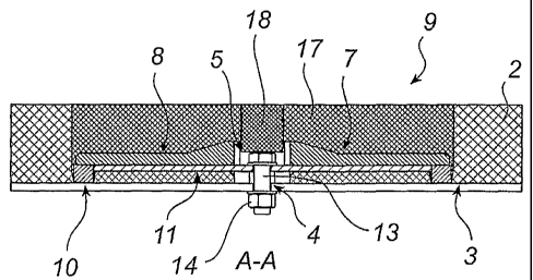
Figs 1 and 2 illustrate a wear lining 19 with a fas-
tening spider 1 which fastens two wear-resistant lining
elements 2 to a support surface 3. The support surface 3
has a mounting point 4 in the form of a through hole.
Figs 3 and 4 illustrate the fastening spider la
which has a central mounting portion 5. The mounting por-
tion 5 has an underside 6, a through hole 7 and four pro-
jecting legs 8a-8d. Each leg has an underside 9 which in
turn has an outer portion 10 and an inner portion 11. In
this embodiment, the outer portion 10 has a supporting
point 12 directed towards the support surface 3. The
fastening of the fastening spider la to the mounting
point 4 occurs by means of a bolt 13 which extends
through the mounting point 4 of the support surface and
the hole 7 of the mounting portion. The bolt 13 is tight-
ened by means of a nut 14.
Fig. 5 illustrates the wear-resistant lining element
2a which is intended for the fastening spider la accord-
WO 2007/008135 CA 02614564 2008-01-07PCT/SE2006/000781
10
ing to Fig. 3. The wear-resistant lining element 2a has
recesses 15 for two of the four legs 8a-8d of the fasten-
ing spider la. A through hole 16 is formed at the end of
the recess 15 and adapted to receive the supporting point
12 of a leg 8a-8d.
In mounting, two wear-resistant lining elements 2a
are placed on the support surface 3 with the recesses 15
of the elements adjoining each other. The fastening
spider la is then placed in the recesses 15 and then
fastens one side each of two wear-resistant lining ele-
ments 2a. The supporting points 12 abut against the sup-
port surface 3 and the legs 8a-8d exert pressure, towards
the support surface, on the surface of the recesses 15 of
the wear-resistant lining element.
When the bolt 13 is tightened, the clamping force
is distributed, via the mounting portion 5, uniformly in
the legs 8a-8d of the fastening spider. In this way,
the holding force of the spider legs against the wear-
resistant lining element 2 or the support surface 3 will
be greater in the outer portions 10 of the legs 8a-8d,
compared with prior art.
With the bolt 13 tightened, the recesses 15 of
the wear-resistant lining element are filled with a fill
spider 17 and, optionally, a fill cylinder 18. The effect
of such filling is that the wear lining 19 will have a
substantially flat and even surface.
Figs 6-8 illustrate a wear-resistant lining element
2b without through holes corresponding to the holes 17 in
the embodiment according to Figs 3-5, and a fastening
spider lb with an arched underside 9. Just like before,
the fastening spider lb has a central mounting portion 5
with an underside 6, a through hole 7 and four projecting
legs 8a-8d. Each leg has an arched underside 9 which in
turn has an outer portion 10 and an inner portion 11.
Mounting is performed in a manner corresponding to the
manner described above.
WO 2007/008135 CA 02614564 2008-01-07 PCT/SE2006/000781
11
Of course, the fastening spider la can be used toge-
ther with the wear-resistant lining element 2b and vice
versa. It is also possible to combine, in terms of con-
struction, the two embodiments of fastening spider and
wear-resistant lining element, respectively. It is also
possible to press a spider into a wear-resistant lining
element without holes or recesses being prepared. How-
ever, in most cases through holes will result in the
safest holding of the wear-resistant lining element.
Depending on how firmly the bolt is tightened, it will
also be possible to obtain a more or less flexibly fas-
tened spider which is allowed to be resilient substan-
tially in the longitudinal direction of the bolt. If
the underside of the spider mounting portion reaches
the support surface during clamping, a rigid joint is
obtained.
The number of legs on the spider is optional, but is
preferably two or four. The wear-resistant lining element
and also the fill spider and/or the fill cylinder can be
reinforced and are preferably made of wear-resistant
elastomeric materials, such as rubber or polyurethane,
but may also be selected from the group consisting of
steel, plastic and composite material, with or without
wear-resistant reinforcements of, for instance, ceramic
material. The spider and/or the support surface can be
made of more or less flexible materials from the group
consisting of steel, plastic and composite material or
a combination thereof. The spider may also be reinforced
in a suitable manner, for instance with reinforcing
irons, carbon or glass fibre or some other plastic or
elastomeric material having a rigidity which is different
from that of the other material of the spider. The number
of supporting points on the underside of the spider leg
may vary between one and as many as can be arranged in
consideration of the length of the underside and the size
of the supporting points.
WO 2007/008135 CA 02614564 2008-01-07PCT/SE2006/000781
12
It will be appreciated that a person skilled in the
art can modify the above-described fastening spider and
the above-mentioned wear lining including a fastening
spider in various ways and still utilise the advantages
of the variants that have been illustrated in the embodi-
ments above.