Note: Descriptions are shown in the official language in which they were submitted.
CA 02614949 2008-01-11
-1-
Description
Cutting insert, tool and method of machining a workpiece
The invention relates to a cutting insert, a tool, and a method of machining a
workpiece,
the cutting insert having an n-angled base body with n>6, the n edges defining
the
n-angled base of said base body being alternately designed as finishing lips
for finish-
machining and as roughing lips for rough-machining of the workpiece.
By roughing or rough-machining, one understands in general a coarse machining
and
by finishing or finish-machining, in general a fine or subsequent machining of
the rough
surface generated by a preceding rough-machining operation.
Such a cutting insert designated as finishing insert is described, for
example, in
WO 97/27967. The finishing insert has a hexagonal base body whose edges are
alternately designed as finishing lips and roughing lips. The roughing lips
are called
major lips and the finishing lips, minor lips. Several of the cutting inserts
are provided
for being arranged on a tool designed as a surface milling cutter, several
roughing
inserts for rough-machining being distributed along the front-face periphery
of the
surface milling cutter and finishing inserts for finish-machining being
arranged at
defined positions.
US 6,604,893 B2 describes a cutting insert with an octagonal geometry, each of
the
eight lateral edges having one finishing lip and one roughing lip. For this
purpose, the
individual lips are arranged at different levels, i.e. they do not lie in the
same plane. To
each lip, a cutting face of an inclined design is adjacent radially to the
center axis of the
cutting insert, so that the surface topography of the cutting insert is very
complex.
When machining a workpiece, in particular with a surface milling cutter, there
is the
problem, in particular at higher feed speeds, that the machined surface has an
insufficient surface quality with bumps in the shape of an arc of a circle.
The invention is based on the task to enable an improved surface quality in
metal-
cutting workpiece machining operations.
The task is solved according to the invention through a cutting insert
according to
patent claim 1. The cutting insert has an n-angled base body with six or more
edges.
The edges defining its n-angled base are alternately designed as finishing
lips and as
roughing lips, each lip being arranged in relation to the lips adjacent to it
at different
angles. Therefore, contrary to conventional cutting inserts, the base body has
an
irregular base. The conventional hexagonal or octagonal cutting inserts each
have a
regular base, so that the individual edges defining the base are arranged at
identical
angles relative to one another.
Due to the irregular design, i.e. the different angles between adjacent lips,
the individual
lips have different lengths. This measure provides that, in comparison with a
regular
design, several lips are displaced a little outwards, i.e. they are located at
a greater
distance from the longitudinal center axis of the cutting insert. Expediently,
these lips in
CA 02614949 2008-01-11
-2-
outward position are the finishing lips. Through this measure, it is achieved
that during
the machining of the workpiece, the finishing lip engages the workpiece
surface over a
relatively large lip length, in addition to the leading roughing lip. As the
finishing lip
engages the workpiece surface over a relatively large length, an efficient
finishing or
fine machining is effected. The surface roughness with the periodically spaced
rib-like
bumps generated by the roughing lip at high feed rates of the tool is
efficiently removed
by the finishing lip, so that as a whole, a surface of a very high surface
quality is
obtained in only one operation, even at a high feed speed.
In view of designing the cutting insert in the simplest possible way, the n
edges forming
the lips are arranged in the same plane.
Preferably, adjacent lips of the cutting insert are arranged alternately at a
large and a
small angle relative to one another. Through the periodically recurrent pairs
of angles,
pairs of lips, each consisting of a roughing and a finishing lip, are formed,
all pairs of
lips being of identical design. In this way, the cutting insert as a whole is
symmetrical. A
cutting insert with a hexagonal base body is, therefore, rotationally
symmetrical relative
to a rotation of 120 around the center axis. This symmetrical design offers
the
particular advantage that the cutting insert can also be mounted in existing
tool carrying
bodies for conventional, regular cutting inserts, without requiring great
changes at the
insert seat in the tool carrying body.
Preferably, the large angle is in each case at least 5 larger than the nth
part of the
angular sum of the n-angled base body. With a six-angled base body, the large
angle
is, therefore, at least 125 . When the angle increases, the finishing lip
moves farther
outwards, so that an increasingly larger length of the finishing lip engages
the
workpiece surface during the machining operation of the workpiece.
The upper limit of the large angle is expediently a value of approx. 140 .
This design
still enables a sufficiently large lead angle of the roughing lip, expedient
for the
machining operation, relative to a machining plane defined by the workpiece
surface.
By lead angle, one generally understands in this case the angle at which the
major or
roughing lip is oriented relative to the machining plane, i.e. the workpiece
surface.
To achieve the largest possible engagement of the finishing lip with the
workpiece
surface, it is provided, according to an expedient development, that the
angular sum of
the lead angle and the large angle amounts to approx. 180 . Through this
measure, it is
achieved that the finishing lip extends substantially approximately parallel
to the
machining plane. Therefore, the large angle is determined as a function of the
lead
angle, through the above-mentioned relationship. With a lead angle of 45 , the
large
angle is, therefore, 135 . As due to the symmetrical design, the large and the
small
angles amount to double the nth part of the angular sum of the n-angled base,
this
determines at the same time the value of the small angle. Therefore, with a
six-angled
basic geometry and a lead angle of 45 , the latter amounts to 105 .
To achieve a clean cutting with the finishing lip designed as the minor lip,
the finishing
lip preferably possesses a slight minor-lip clearance relative to the
machining plane. By
minor-lip clearance, one understands here a spacing of the finishing lip from
the
CA 02614949 2008-01-11
-3-
machining plane, namely in the rear area of the finishing lip, which is spaced
from the
roughing lip designed as the major lip.
To form this minor-lip clearance, it is in principle possible to design the
minor lip in a
way inclined towards the machining plane at a slight angle of, for example 1
to 2 . In
this case, the finishing lip would no longer be parallel to the machining
plane and the
angular sum of the lead angle and the large angle woud be reduced by this
angle and
would be less than 180 .
Preferably, however, for forming the minor-lip clearance, the finishing lip is
designed as
a so-called wiper lip. Expediently, it is provided in this case that the
finishing lip is of a
slightly rounded design and extenda along a curvature. The latter is in
particular a
circular curve with a very large radius, preferably in the range between 500
mm and
3000 mm. Through the design of the finishing lip as a curved lip, contrary to
a lip
extending in a straight line, the finishing lip has in the corner area next to
the leading
roughing lip a highest point, so that the finishing lip engages the workpiece
surface in a
defined manner. Due to the arc-shaped design of the finishing lip, the
distance from the
machining plane and, therefore, the minor-lip clearance increases increasingly
in the
further course of the finishing lip.
Expediently, the cutting insert is provided for a lead angle between 40 and
55 , in
particular for a lead angle of 45 . As the values of the large and small
angles are
determined as a function of the lead angle, a special cutting insert is
provided for each
lead angle. Preferably, the cutting insert, based on a hexagonal basic
geometry,
possesses a six-angled basic geometry.
To enable the longest possible tool life of the cutting insert, the latter is
preferably
designed as a double-sided indexable insert with 2n lips, i.e. lips are formed
both on its
top side and on its bottom side. As due to the chosen special design, a pair
of lips
consisting of a roughing lip and a finishing lip engage the workpiece in each
case during
a machining operation, the cutting insert can be indexed only n/2 times per
side.
Therfore, with a six-angled basic geometry, the cutting insert can be indexed
3 times
per side and altogether 6 times, until it is completely worn.
The task is, furthermore, solved according to the invention by a tool with the
features
according to patent claim 13 or 14 as well as by a method with the features
according
to patent claim 15. The advantages and preferred embodiments of the cutting
insert
can analogously be applied to the tool and to the method, too.
According to an expedient embodiment, the tool comprises a tool carrying body
having
an insert seat having at least two front-face bearing faces on which two of
the front-face
sides of the cutting insert planely abut in mounted position. Between the
bearing faces,
a holding pocket forming a clearance is provided. The insert seat can be
designed
directly in the tool carrying body or in an exchangeable cassette. In mounted
position,
one cutting corner of the cutting insert protrudes into the clearance, without
abutting on
the insert seat in this area. Due to this measure, the tool carrying body is
also suitable
for receiving conventional cutting inserts with equal-sided n-angled, for
example
hexagonal, geometry and can, therefore, optionally be fitted with conventional
cutting
CA 02614949 2008-01-11
-4-
inserts or with the cutting inserts described here. The two bearing faces are
for this
purpose oriented along the sides of an equal-sided n-angled surface, in which
each two
adjacent edges include the same angle between them. Therefore, with a
hexagonal
basic geometry, the two bearing faces (the imaginary extensions of the bearing
faces
into the holding pockets) include an angle of 600, so that the front-face
sides of a
conventional hexagonal cutting insert also planely abut on the bearing faces.
Exemplary emboidments of the invention are explained in detail in the
following by
means of the drawing, in which, partly in schematic representations
Fig. 1 is a perspective view of a tool designed as a surface milling cutter,
Fig. 2 is a sectional view of the surface milling cutter according to Fig. 1,
Fig. 3 is an enlarged, simplified detail view of a cutting insert in its
mounting position in
an insert seat of a tool carrying body,
Fig. 4 is a simplified view of an insert designed for a lead angle of 40 ,
Fig. 5 is a simplified view of an insert designed for a lead angle of 55 ,
Fig. 6 is a simplified perspective view of a cutting insert,
Fig. 7 is a front-face view of a cutting insert, and
Fig. 8 is an enlarged view of the detail marked with a circle in Fig. 2 in the
area of the
rounded transition from a roughing lip to a finishing lip.
In the figures, parts having the same function are marked with the same
reference
numbers.
The tool designed in the exemplary embodiment as a surface milling cutter 2
comprises
a tool carrying body 4 having a front-face machining side 6. A number of
cutting inserts
8 are arranged on, and distributed over, the periphery of the machining side
6. Each of
the cutting inserts 8 lies in an insert seat 10 formed directly into the tool
carrying body 4
(cf. Fig. 2 and 3). Alternatively to this, it is possible to arrange the
cutting inserts 8 in
cassettes which, in turn, are held in the tool carrying body 4. The cutting
inserts 8 are
held in a defined position in the tool carrying body 4 by means of screws 12.
To machine a workpiece surface, the machining side 6 of the surface milling
cutter is
brought into engagement with the workpiece surface, the workpiece surface
defining a
machining plane 14, which can be seen in particular in Fig. 2. The machining
plane is
defined by the individual cutting inserts 8 of the surface milling cutter 2.
The lips 16A,B are designed as major and minor lips and merge into each other
via a
rounded cutting corner 17. The cutting insert 8 is preferably designed as a
double-sided
indexable insert whose edges are designed as lips 16A,B. One of the lips,
namely a
roughing lip 16A, is arranged relative to the machining plane 14 at a lead
angle x, which
in the exemplary embodiment is 45 .
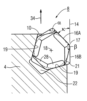
The basic geometry of the cutting insert 8, i.e. its cross-sectional area
oriented perpen-
dicularly to its center axis 18, as well as its mounting position in the
insert seat 10 will
be explained by means of Fig. 3. In the exemplary embodiment, the cutting
insert 8
possesses a six-angled basic geometry, based on a regular hexagonal cross-
section
geometry. The insert seat 10 has two bearing faces 19, on which two front-face
sides
CA 02614949 2008-01-11
-5-
20A,B (cf. Fig. 6) of the cutting insert 8 abut. The bearing faces 19 include
an angle of
600, whereby the insert seat 10 is also designed in particular for receiving a
conven-
tional hexagonal cutting insert. The cross-section geometry of such a
conventional
cutting insert is indicated in Fig. 3 by a dash-dotted line forming a hexagon
21. The
insert seat 10 has on its rear side a holding pocket 22, into which a partial
area of the
cutting insert 8 protrudes.
Contrary to the hexagonal cross-sectional area, the cutting insert 8 is of an
irregular
design, in that the edges of the cutting insert 8 forming the individual lips
16A,B are
arranged alternately at a small angle a and a large angle R relative to one
another. In
Fig. 3, the lead angle x is 450, each small angle a is 105 and each large
angle R is
135 . Due to the irregular design, alternately a long lip 16A and a shorter
lip 16B are
formed in pairs, the longer lip 16A being designed as a roughing lip and the
shorter lip
16B, as a finishing lip in the manner of a wiper lip.
As is directly recognizable through a comparison with the hexagonal geometry
represented in dash-dotted lines, the finishing lip 16B is displaced a little
outwards from
the center axis 18 towards the machining plane 14, due to the irregular
design. In the
exemplary embodiment, the angles a, R as well as the lead angle x are chosen
such
that the finishing lip 16B extends substantially parallel to the machining
plane 14.
Furthermore, an incircle 24 is drawn in Fig. 3 in dash-dotted lines. The
individual sides
of the hexagon 21, also drawn in dash-dotted lines, form tangents of this
incircle. The
bearing faces 19 also form tangents of the incircle 24. The cutting insert 8
in its irregular
design is designed in such a way that alternately every second edge, i.e. in
each case
the roughing lip 16A, also touches the incircle 24 tangentially. This design
guarantees
that the cutting insert 8 having the irregular geometry can also be used in
insert seats
for conventional hexagonal cutting inserts. Only the holding pocket 22 at the
bottom
of the insert seat is necessary for receiving the finishing lip 16B.
Fig. 3 also indicates in a schematic and greatly simplified manner, adjacent
to the
individual lips 16A, 16B, chip breakers 28, which in the exemplary embodiment
are
formed in the manner of dimples extending in a straight line. The chip
breakers 28
serve for a specific and defined treatment of the chip removed by the lips
16A,16B, i.e.
for a specific chip guidance, chip forming and also for a specific breaking of
the chip.
The chip breakers can also be designed with other geometries.
Fig. 4 and 5 show cutting inserts 8 designed for a lead angle x of 40 (Fig.
4) and for a
lead angle x of 55 (Fig. 5).
For the cutting insert 8 according to Fig. 4 and the lead angle x of 40 , the
large angle R
is 140 and the small angle a, 1000.
For the cutting insert 8 according to Fig. 5, designed for a lead angle x of
550, on the
other hand, the large angle p is 125 and the small angle a, 115 . The angular
sum of
these two angles is in each case 240 , i.e. double the value of the angle of
120
between two adjacent sides of a regular hexagon 21.
CA 02614949 2008-01-11
-6-
By means of the perspective view of the cutting insert 8 according to Fig. 6,
one recog-
nizes that the lips 16A,B lie in the same plane. The cutting insert 8 has a
top side 30
and a bottom side 32 opposite this top side 30 and in plane-parallel
orientation to it.
Both the edges of the top side 30 and the edges of the bottom side 32 are
designed as
lips 16A,B. Opposite lips 16A,B of the top side 30 and of the bottom side 32
are
connected with one another through the front face 20A,B of the cutting insert
8.
Opposite lips 16A,B lie in the same plane, which is arranged at right angles
to the
planes defined by the top side 30 and the bottom side 32. The front face
connecting the
two opposite roughing lips 16A with one another is marked with the reference
number
20A and the front face connecting the two opposite finishing lips 16B with one
another
is marked with the reference number 20B.
In the exemplary embodiment according to Fig. 6, in which the cutting insert 8
is
designed as a double-sided indexable insert, the front face 20B connecting the
finishing
lips 16B opposite one another, has two partial front faces. These two partial
front faces
are arranged with an inward inclination towards each other at an angle y (cf.
Fig. 7).
This inclined arrangement can be seen in particular also from the
representation
according to Fig. 7, which shows a side view of the front faces 20A,B of a
cutting insert
8 designed as an only one-sided indexable insert. The front face 20B, which is
here of a
one-piece design, is inclined towards the top side 30, as compared with the
perpen-
dicular, at the angle y. The angle y is in the exemplary embodiment 2 and
preferably
lies in the range between 0.5 and 5 . The angle y as a whole is designed in
the
manner of a clearance angle and the front face 20B forms a flank towards the
finishing
lip 16B. In the double-sided indexable insert according to Fig. 6, the two
partial front
faces are, therefore, starting from opposite finishing lips 16B arranged in
each case
with an inward inclination towards each other at the angle y and meet on a
common
center line 36.
To achieve the best possible cutting result, the finishing lip 16B is designed
as a wiper
lip. The enlarged view of the detail in the area of the rounded cutting corner
17, marked
with a circle in Fig. 2, one can see that the rounded transition from the
roughing lip 16A
to the finishing lip 16B is composed of several radii rl,r2, the radius r,
oriented towards
the roughing lip 16A having a smaller value than the radius r2 oriented
towards the
finishing lip 16B. Through this measure, a better surface quality of the
machined
workpiece is achieved.
Fig. 8 also shows that another, very large radius r3 is adjacent to the second
radius r2.
The circular curve or curvature defined by the large radius r3 defines the
course of the
finishing lip 16B. That means that the finishing lip 16B as a whole is
designed with a
curved or arc-shaped course. Depending on the application, the radius r3 lies
in a range
between 500 mm and 3000 mm. Due to the very large diameter, the finishing lip
16B
appears as a straight line, even in the enlarged representation according to
Fig. 8. Due
to the rounded design, the highest point of the finishing lip 16B, relative to
the machin-
ing plane 14, is immediately adjacent to the cutting corner 17. With
increasing distance
from the cutting corner 17, the finishing lip 16B increasingly moves away from
the
machining plane 14, so that a minor-lip clearance A is formed. Therefore, the
minor-lip
clearance A defines a distance between the finishing lip 16B and the machining
plane
CA 02614949 2008-01-11
-7-
14. In the exemplary embodiment, the minor-lip clearance A is exclusively
formed by
the curved course of the finishing lip 16B.
In the figures, the cutting insert 8 was described in connection with the
surface milling
cutter 2 as the tool and with a six-angled base. In principle, such a cutting
insert is also
possible for other tool types and also with other basic geometries, for
example an 8, 10
or 12-angled base.
When machining the surface of a workpiece, the surface milling cutter 2
rotates on the
one hand about its longitudinal and rotational axis. In the representation
according to
Fig. 3, the rotational axis lies in the plane of the paper in a horizontal,
i.e. perpendicular
to the machining plane 14. At the same time, the surface milling cutter 2 is
traversed in
the feed direction 34 indicated by an arrow 34 (cf. Fig. 2 and Fig. 3),
parallel to the
machining plane 14. Through this movement, the roughing lip 16A continually
removes
material from the top side of the workpiece. The workpiece surface rough-
machined by
the roughing lip 16A is immediately afterwards finish-machined by the adjacent
finishing
lip 16B of the same cutting insert 8, said finishing lip 16B being in the
exemplary em-
bodiment effective over its entire length through its orientation parallel to
the machining
plane 14. In this way, a very efficient finish-machining is achieved and a
very high
surface quality of the machined workpiece is achieved.