Note: Descriptions are shown in the official language in which they were submitted.
CA 02614954 2007-12-14
PRODUCT DEMONSTRATION SYSTEM
CROSS-REFERENCE TO RELATED APPLICATION
This application is a continuation-in-part of International Patent Application
No. PCT/ US2006/022420, filed June 8, 2006, and International Patent
Application
No. PCT/US2006/022503, filed June 9, 2006.
BACKGROUND OF THE INVENTION
Field of the Invention
The invention relates to demonstrations of products offered for sale, and more
particularly to systems and devices to effect sales demonstrations of
products.
Description of the Related Art
Products are often made in a variety of models, each having more or less
components that offer different features and operational modes. Cars and
computers,
for example, often have dozens of configurations across the same product line.
Household appliances are manufactured in a large variety of shapes, sizes, and
colors,
and with many different operating features. Vendors of these products
typically
employ sales persons to demonstrate the various features of a product to
potential
purchasers.
Manufacturers often make demonstration models of their products for the
express purpose of enabling customer demonstrations of the features that the
manufacturer wishes to highlight. A demonstrational or demo home appliance not
available for purchase may be semi-functional, built to look the same as a
production
line appliance, but missing many operational elements. For example, a
demonstration
oven might have the capability to guide a user through an input sequence for
specifying cooking temperature and cooking time, but no heat elements would be
included in the demo oven. Because demo appliances are not constructed with
the
same elements and functionality as a production line appliance, the two
versions of
the appliance must be manufactured separately, which complicates the
manufacturing
process and adds costs.
It is also known to incorporate software into a product that will cause the
product to go into a demonstration mode on order to show selected features of
the
product. For example, a television might be instructed to play a demonstration
video
while showing different features of a built-in audio system. Home appliances
are
I
CA 02614954 2007-12-14
sometimes manufactured so that they may be operated in a demo mode. In such
cases, it is known to upload or change embedded demonstration software in a
product
such as an appliance as demonstration needs change. But too often, the needs
of a
sales demonstration far exceed the capability of built-in software to
accommodate
them.
It is also known for a manufacturer to hard-code a demo mode into a product
such as an appliance before shipping the product to a vendor. Demonstrations
are
thus not tailored to target the needs of each individual vendor, and
promotional offers,
which only last a short amount of time, cannot be included in the
demonstrations. In
rare instances, a computer can be connected to the appliance to alter the
programming. However, this involves disassembling the appliance and/or re-
writing
the code, necessitating the involvement of experienced mechanics and/or
programmers. As this consumes excessive time and resources, most demo
appliances
are simply discarded when the demonstration becomes outdated.
SUMMARY OF THE INVENTION
The invention lies in a product demonstration system including a product
having an internal communications network among two or more components. In one
aspect, the product has software architecture implemented on the network that
identifies the components, communicates the capabilities of each identified
component, communicates the status of each identified component, provides a
command interface for operating the components, and facilitates communication
between the components and devices external to the product. A smart device
having
demonstration software is in communication with the internal communications
network and in control of at least one of the components. In this way,
execution of
the demonstration software in the smart device will cause demonstration of one
or
more of the components in the product.
An example of the product is a household appliance. The system can also
have one or more interactive devices connected to the product in communication
with
the internal communications network. Preferably, the interactive device can be
selected from a group comprising a proximity sensor, an LCD display, a
speaker, a
computer, a touch screen, a keyboard, a monitor, a mechanical device, a light
display,
a microphone, a camera, and a phone.
2
CA 02614954 2007-12-14
The interactive device can be connected to the smart device. As well, the
smart device can have a communication link to an external network whereby the
demonstration software can be changed by way of the external network. The
smart
device is preferably in control of all of the components.
In another aspect of the invention, an appliance demonstration system includes
a household appliance having an internal communications network among two or
more components. A smart device having demonstration software is in
communication with the internal communications network and in control of at
least
one of the components. In this way, execution of the demonstration software in
the
smart device will cause demonstration of the one or more of the components in
the
appliance.
BRIEF DESCRIPTION OF THE DRAWINGS
In the drawings:
Figure 1 is a schematic illustration showing a household appliance having an
internal communication network connected to a smart device according to the
invention.
Figure 2 is a schematic illustration of the household appliance and the
connected smart device of Figure 1 and further incorporating a plurality of
connected
demo devices.
Figure 3 is a schematic illustration of the smart device of Figure 1 in use
with
a component of the appliance and a demo device and showing the capabilities of
the
component and the demo device.
Figure 4 is a schematic illustration of the smart device, component, and demo
device of Figure 4 and showing communication via messages therebetween.
Figure 5 is a perspective view of a dryer capable of connecting to a smart
device according to one embodiment of the invention.
Figure 6 is a schematic illustration of the interior of the dryer of Figure 5.
Figure 7 is a perspective view of a user interface on the dryer of Figure 5.
Figure 8 is a flow chart illustrating normal operation of the dryer of Figure
5.
Figure 9 is a perspective view of a smart device for connection to the dryer
of
Figure 5.
Figure 10 is a perspective view of an LCD monitor for connection to the smart
device of Figure 9.
3
CA 02614954 2007-12-14
Figure 11 is a perspective view of an air flow demo unit for connection the
dryer of Figure 5.
Figure 12 is a perspective view of the smart device of Figure 9, the LCD
monitor of Figure 10, and the air flow demo unit of Figure 11 in use with the
dryer of
Figure 5.
Figure 13 is a flow chart illustrating a sales demo to be executed and
performed by the smart device, LCD monitor, air flow demo unit, and dryer of
Figure 12.
Figure 14 is a schematic illustration of a business method for use with the
invention of Figure 12.
Figure 15 is a flow chart illustrating the affect of various factors on
business
concepts for inclusion in the sales demo of Figure 13.
DETAILED DESCRIPTION
The invention provides a way to enable a production line product to operate in
a demonstration mode, completely controlled from an external device adapted
for that
purpose. And it does much more as explained below. The invention centers
around a
smart device connectable to any production product having an internal
communications network connecting two or more functional components. The smart
device contains demonstration software capable of assuming control of the
components in the product and operating them independently of a sales person,
but
interactively with a potential customer. An example of such a product might be
a
hybrid automobile with a internal communications network connecting an
electric
motor with a gasoline engine. The smart device in accord with the invention,
can
demonstrate features of the automobile inside a showroom in a demonstration
mode
without having to start the gasoline engine. Another common product type for
which
the invention can find applicability is in the field of home appliances.
Household appliances typically comprise one or more components which
perform the electromechanical operations of the appliance. By employing a
software
architecture that enables facile communication between internal components of
an
appliance and between an external component and one or more of the internal
components of the appliance, various components and accessories can
communicate
with the appliance to expand the capability, functionality, and usability of
the
appliance. The appliance can be any suitable appliance, such as a household
4
CA 02614954 2007-12-14
appliance. Examples of household appliances include, but are not limited to,
clothes
washing machines, clothes dryers, ovens, dishwashers, refrigerators, freezers,
microwave ovens, trash compactors, and countertop appliances, such as waffle
makers, toasters, blenders, mixers, food processors, coffee makers, and the
like.
The appliance can be configured to perform a cycle of operation to complete a
physical domestic operation on an article. Examples of the physical domestic
operations include a food preparation operation, a food preservation
operation, a fluid
treatment operation, a cleaning operation, a personal care operation, a fabric
treatment
operation, an air treatment operation, and a hard surface treatment operation.
The air
treatment operation can comprise, for example, air purification, air
humidification, air
dehumidification, air heating, and air cooling. The food preparation operation
can
comprise, for example, food cleaning, food chopping, food mixing, food
heating, food
peeling, and food cooling. The food preservation operation can comprise, for
example, food cooling, food freezing, and food storage in a specialized
atmosphere.
The fluid treatment operation can comprise, for example, fluid heating, fluid
boiling,
fluid cooling, fluid freezing, fluid mixing, fluid whipping, fluid dispensing,
fluid
filtering, and fluid separation. The cleaning operation can comprise, for
example,
dishwashing, fabric washing, fabric treatment, fabric drying, hard surface
cleaning,
hard surface treatment, hard surface drying, carpet cleaning, carpet
treatment, and
carpet drying. The personal care operation can comprise, for example, hair
treatment,
nail treatment, body massaging, teeth cleaning, body cleaning, and shaving.
The internal components of the appliances can include anything that
participates in the operation of the appliance. Examples include a controller
(main
controller, motor controller, user interface, etc.), which can be a simple
microprocessor mounted on a printed circuit board, standing alone or
associated with
a corresponding device. Other examples include one or more devices such as
pumps,
motors, heaters, I/O devices and that like that may or may not be controlled
by a
controller. Typically, the controller components in cooperation either
directly or
indirectly, through other components, control the operation of all of the
components
and the associated devices to implement an operation or cycle for the
appliance.
The software architecture can be implemented on and communicate over an
intemal communications network on the appliance. The internal communications
network connects the various internal components of the appliance and can be
considered a closed network. One example of the internal communications
network
CA 02614954 2007-12-14
used within an appliance is the WIDE network protocol, created by Whirlpool
Corporation, the assignee of the present patent application.
The software architecture can also expand the communication ability of the
appliance by effectively creating an open network Within the appliance, the
software
architecture can, but does not have to, reside on each of the components that
have a
controller. Those components with the software architecture form a network
node
that can communicate with the other nodes.
The software architecture can perform multiple functions. For example, one
function can relate to identifying each of the components corresponding to a
node on
the network, while another function can relate to identifying capabilities or
functions
of the identified components on the network. Yet another exemplary function is
to
identify the status of the components on the network. In this way, the
software
architecture can function to inform all of the nodes on the network of the
presence,
capabilities, and status of the other nodes.
The software architecture can comprise multiple modules, each of which has
different functionality. Various combinations of the modules or all of the
modules
can reside on each of the components. One module having a basic or core
functionality resides on all of the components. In one anticipated
configuration, all of
the modules reside at least on the main controller, which establishes the main
controller to function as a primary or main software architecture, with the
other nodes
functioning in a client relationship to the main software architecture. In
such a
configuration, all of the nodes can communicate through the main software
architecture. The software architecture can be sufficiently robust that it can
permit
configurations without a main software architecture or with multiple main
software
architectures. For example, the controllers of the various components can work
together to control the operation of the appliance without any one of the
appliances
functioning as a main controller. Regardless of the configuration, any
component
with the software architecture can function as a client with respect to the
other
components.
Because of the software architecture, the internal components of the appliance
are not only connected with one another, but the internal components can also
be
connected to one or more external components or a new internal component
through
the network. The external component and/or the new internal component has one,
some, or all of the software architecture modules in resident. As a result,
the external
6
CA 02614954 2007-12-14
component and/or the new internal component can communicate with the internal
components of the appliance and can also communicate with other external
components having the software architecture.
The software architecture can enable communication between the internal
components of the appliance and the external component and/or the new internal
component or between components external to the appliance. An example of such
a
software architecture is disclosed in the parent Application No.
US2006/022420, titled
"SOFTWARE ARCHITECTURE SYSTEM AND METHOD FOR
COMMUNICATION WITH, AND MANAGEMENT OF, AT LEAST ONE
COMPONENT WITHIN A HOUSEHOLD APPLIANCE," filed June 8, 2006, and
incorporated herein by reference in its entirety. All of the communications
between
internal and external components and/or any combination of components
described in
this application can be implemented by the software and network structures
disclosed
in this application.
The software architecture can be implemented by providing one or more of the
software elements of the software architecture at least on each of the
internal and
external components to be controlled. The software architecture is preferably
configured to generate a plurality of messages, with at least one of the
software
elements residing in each of the components and configured to enable
transmission of
at least one of the plurality of messages between the components. The messages
can
be transmitted for bi-directional communication between components. The
messages
can include command messages that are used to implement a physical domestic
operation cycle of the appliance.
The messages can be generated by a message generator, which can take the
form of the software architecture, an external component, or an internal
component.
One possible message generator is a user interface. It will thus be apparent
that an
internal communications network in the product can be formed of the software
architecture resident on a single controller, which, in turn, is connected to
one or more
devices, none of which have its own controller or software. Also, the internal
communications network can be formed of multiple devices, any one or more of
which may have a separate controller.
Figure 1 illustrates the invention in the context of a household appliance,
designated generally by the numeral 10 in a schematic diagram. The appliance
10 in
this embodiment can be any from the group of appliances discussed previously,
or any
7
CA 02614954 2007-12-14
similar product. The appliance 10 preferably includes the previously discussed
software architecture having an internal communication network 12
interconnecting a
plurality of components 14, wherein each component is capable of communicating
with the network 12 by way of the software architecture. The components 14 are
conventional and include, for example, motor control microprocessors, key
pads,
timers, displays, and other devices and controls typically included within the
household appliance 10. It is to be understood that the appliance 10 in the
context of
the invention is a production unit that can be purchased by a customer from a
vendor
for immediate use without modifications.
The appliance 10 can include a user interface 16 as is commonly used with
appliances. The user interface 16 enables a user to actuate and specify the
parameters
for various operations of the appliance 10. The user interface 16 can include,
but is
not limited to, any number of well-known features, such as a digital display,
speakers,
a touch screen, a key pad, buttons, switches, dials, lights, and the like.
The household appliance 10 has an internal/external communications
connection 18. The internal/external communications connection 18 can be any
suitable connecting device, such as a wire or wireless port, an Ethernet
connector, a
wireless-G connector, a USB port, a serial port, and the like. The
internal/external
communications connection 18 is capable of connecting to various network
interface
devices 20 for enabling communication with various external clients or
devices.
Examples of suitable external network interface devices 20 comprise any
suitable and
well-known serial, wireless, infrared, USB and TCP/IP device which would be
apparent to one skilled in the art. The connection between the
internal/external
communications connection 18 and the network interface device 20 can be made
permanent or temporary. One extetnal client that can be connected to the
appliance
via the internal/external communications connection 18 by way of the network
interface devices 20 is a smart device 30, according to the invention. The
smart
device 30 is operably coupled to a network interface device 20.
Referring now also to Figure 2, the smart device 30 can itself comprise a
network interface device 20 for removably coupling to the internal/external
communications connection 18 of the appliance 10. The smart device 30
comprises a
read-write memory component 32 and a controlling component 34, and can be a
dedicated device, or be incorporated in such devices as a laptop computer,
remote
control, a PDA, a cell phone, or a dongle. The smart device 30 can be powered
by
8
CA 02614954 2007-12-14
any suitable means, such as by an internal battery or from a connection to an
outside
power source. The smart device 30 can include power transmission means for
delivering power to the appliance 10, such as through the communications
connection
18. Since, according to the invention, the smart device 30 will control the
appliance
in a sales demonstration mode, as explained below, it need only deliver enough
power to the appliance to effectively operate such a mode. The smart device 30
can
also be enabled to connect to other devices (such as the internet) by way of
additional
internal/external communications connections 18 and other network interface
devices 20.
The smart device 30 will have its own software capable of communicating
with the internal communication network 12 in the appliance 10. According to
the
invention, when the smart device 30 is coupled to the appliance 10, the smart
device
30 assumes at least some control of the individual components 14 of the
appliance 10.
For example, the smart device 30 can assume complete control of the appliance
10
and command the appliance 10 to enter a passive state. The smart device 30 can
automatically assume control of the appliance 10 upon connection of the smart
device
30 to the internal/external communications connection 18. Alternatively,
additional
stimulation can be required to initiate control of the appliance 10 via the
smart device
30, such as by flipping a switch on the smart device 30 or the appliance 10,
or by
entering a specific key sequence on the user interface 16. Once the smart
device 30
has established control of the appliance 10, the smart device 30 can operate
the
various components 14 of the appliance 10 in a manner different than the
components
14 would be operated during normal operation. This unique ability enables the
smart
device 30 to change the operational capabilities and behavior of the appliance
10
temporarily without requiring any modifications of the appliance 10 or its
components 14.
The smart device 30 can use its memory component 32 to store sales
demonstration software, for example, hereinafter referred to as "sales demos",
which
can be accessed by the controlling component 34. The controlling component 34
can
communicate with and control the appliance 10 to execute the sales demos.
Sales
demos can be designed to highlight features of the appliance 10 for the
customer and
can be interactive with the customer. Exemplary sales demos include, but are
not
limited to, video presentations, audio presentations, displaying promotions
and/or
advertisements, light and sound shows, textual displays, 3-D simulations,
slideshows,
9
CA 02614954 2007-12-14
voice feedback, key presses, voice command and control, motion sensing,
mechanical
system custom demonstrations, and any combination thereof. Sales demos can be
updated, deleted, modified, and downloaded to the memory component 32 of the
smart device 30. This can be accomplished by connecting a network interface
device
20 to an appropriate source (such as the internet) by way of an
internal/external
communications connection 31 of the smart device 30. Examples of appropriate
source include, but are not limited to, a computer, a PDA, a remote control, a
cell
phone, a dongle, an i-Pod , the internet, and a USB drive. Sales demos can
thus be
made adaptable to the needs of different vendors and/or manufacturers by
downloading different sales demos and/or modifying or updating existing sales
demos
accordingly.
As the software architecture enables control of individual components 14 of
the appliance 10, the smart device 30 can take advantage of this capability
and
combine the control of the components 14 with the control of one or more demo
devices 40. A demo device 40 can be a device external to the appliance 10 that
aids
in the presentation of sales demos. The demo devices 40 will be expected to
have
their operation controlled at least in part by the smart device 30. Examples
of such
devices include, but are not limited to, a proximity sensor, an LCD display, a
speaker,
a computer, a touch screen, a keyboard, a monitor, a mechanical device, a
light
display, a microphone, a camera, a phone, or the like. Demo devices 40 can be
completely or partially controlled by the smart device 30. Demo devices 40 can
be
embedded in the smart device 10. Demo devices 40 can instead comprise a
network
interface connection 20 and can be connected to either the appliance 10 or to
the
smart device 30 via an additional internal/external communications connection
18.
Each demo device 40 can be enabled with the same software architecture as the
appliance 10 whereby the demo device 40 establishes a node on the internal
communication network 12 or is part of an existing node on the network 12. If
a
demo device 40 is not enabled with the same software architecture as the
appliance
10, the smart device 30 can optionally serve as a protocol bridge between the
demo
device 40 and the appliance 10. A protocol is a standard procedure for
regulating data
transmission between devices; however, not all devices necessarily communicate
in
the same protocol. A bridge effectively translates one protocol into another
so that
devices with different protocols can communicate with one another. Thus, the
bridge
functionality can be incorporated into the smart device 30 and the user does
not need
CA 02614954 2007-12-14
to purchase a separate bridge in order for the demo device 40 to communicate
across
the internal communication network 12.
In order to present the sales demos, the smart device 30 can utilize both the
internal components 14 of the appliance 10 and/or demo devices 40, an example
of
which is illustrated in Figure 3. An internal component 14 and a demo device
40 can
each have visual output 44, audio output 46, and/or sensory output 48
capabilities
which can serve a number of purposes, such as encouraging customers to
interact with
the appliance 10, offering product information and demonstrations, and
presenting
various promotions and advertisements. The internal component 14 and demo
device
40 can also have visual input 54, audio input 56, and/or sensory input 58
capabilities
which can serve additional purposes, such as answering customer questions,
responding to customer commands, and collecting information regarding the
customer
and his or her behavior. The internal component 14 and demo device 40 can be
controlled to operate passively or to require customer actuation for
operation.
Referring now to Figure 4, the smart device 30 can also command the internal
component 14 and demo device 40 to work in combination with other internal
components 14 and/or demo devices 40. For example, a component 14 or demo
device 40 capable of receiving sensory input 58, such as a button or a motion
sensor,
can send a detailed message 60 across the internal communication network 12
upon
receiving sensory input 58 from a customer. A demo device 40 or an internal
component 14 having visual output 44 means, such as a light on the appliance
10 or
an LCD screen hanging above the appliance 10, can receive the message 60 and
provide certain visual output 44 responsive to the sensory input 58. The
relationships
between components 14 and demo devices 40 and the reactions to messages sent
therebetween can be controlled by the smart device 30.
An example of a household appliance according to the invention is illustrated
in Figures 5 and 6 as a dryer. The clothes dryer 100 described herein shares
many
features of a well-known automatic clothes dryer, and will not be described in
detail
except as necessary for a complete understanding of the invention. In this
example,
the dryer 100 includes a feature wherein the dryer 100 can adjust the pressure
in the
flow of air to accommodate different load types and different home venting
systems.
The dryer 100 includes a plurality of elements common to a dryer, such as a
cabinet
102 having a user interface 104 for controlling the operation of the dryer
100, a
partially translucent door 106 hingedly attached to a front wall 120 of the
cabinet 102,
11
CA 02614954 2007-12-14
a rear wall 124, and a pair of side walls 122 supporting a top wall 118. Two
internal/external communications connections in the form of two USB ports 190,
192
are located on the user interface 104.
Looking now more closely at Figure 6, the interior 128 of the dryer 100
comprises a rotating drum 130 having an open front for access to the interior
of the
drum 130 which defines a drying chamber 132. The cabinet 102 also encloses a
drum
motor assembly 133 adapted in a well-known manner for rotating the drum 130
via a
drum belt 134. A blower assembly 140, a flexible dryer hose or similar conduit
142,
and a heater assembly 144 in fluid connection with one another and the drying
chamber 132 are also enclosed by the cabinet 102. An exhaust (not shown) is
provided in the rear wall 124 of the dryer 100 for connection to a home
venting
system (not shown) for venting air.
In normal operation of the dryer, a user first selects an appropriate drying
cycle by means of the user interface 104. Figure 7 illustrates various
features that can
be included on the user interface 104, including a power button 148, dryer
status
indicator lights 150, a dial 152, parameter adjusting buttons 154, a digital
display 156,
a start button 160, a stop button 162, a first parameter selection button 166,
a first set
of indicator lights 168, a second parameter selection button 170, and a second
set of
indicator lights 172, on/off buttons 178, and on/off indicator lights 180.
These
features can be marked with appropriate indicia to indicate their function.
Selecting
the drying cycle can require a user to manipulate several of these features to
initiate
operation and specify common drying cycle parameters. Examples of such
parameters include, but are not limited to cycle type, heat level, dryness
level, air
level, temperature, and cycle length.
For the particular dryer 100 described herein, normal operation of the dryer
100 comprises a number of steps 65, 66, 67, 68, and 69 as illustrated in
Figure 8.
Each step is illustrated herein as a box. A feature on the user interface 104
that can be
manipulated to effect or affect a given step is illustrated as a circle having
an arrow
pointing therefrom towards the given step. A feature on the user interface 104
that
produces visual output at a given step is illustrated as circle having an
arrow pointing
thereto from the given step. A first step that must be completed prior to the
beginning
of a second step is signified by a thickened arrows pointing from the first
step towards
the second step.
12
CA 02614954 2007-12-14
A user powers up the dryer 100 at a power-on step 65 by pressing the power
button 148. At least one of the status indicator lights 150 associated with an
"on"
state of the dryer 100 will become lit upon pressing of the power button 148.
Next, a user can select the drying cycle parameters at a parameter selection
step 66. The dial 152 can be rotated to select an appropriate drying cycle
type.
Examples of specific drying cycles include, but are not limited to, a touch-up
cycle,
an express dry cycle, a timed dry cycle, a heavy duty cycle, a cotton/towels
cycle, a
normal cycle, a bulky/bedding cycle, cottons cycle, a delicates cycle, a
linens cycle.
If the drying cycle type is a timed drying cycle, the user can select a
desired cycle
length using the parameter adjusting buttons 154 to adjust the number of
minutes that
the cycle will last. The user can also select a desired dryness level and a
drying
temperature using the first parameter selection button 166 and the second
parameter
selection button 170 respectively. The first set of indicator lights 168 and
the second
set of indicator lights 172 correspond to the first parameter selection button
166 and
the second parameter selection button 170 respectively. Each light in each set
168,
172 correspond to a different dryness level and a different temperature level
respectively. The buttons 166, 170 can be pressed repeatedly to select the
different
levels.
Once the parameter selection step 66 is complete, the user can press the start
button 160 to begin the drying cycle step 67. As is well-known, the door 106
includes
sensing means (not shown) to ensure that the drying cycle will not start if
the door
106 is not closed. In accordance with the selected parameters, various
components 14
of the dryer will perform a drying cycle. Throughout the drying cycle, the
dryer
status indicator lights 150 will reflect the operation of the dryer 100. The
motor
assembly 133 rotates the drum 130 via the belt 134. The blower assembly 140
draws
air out of the drying chamber 132 and into a flexible dryer vent hose 142. The
blower
assembly 140 then circulates the air through a heater assembly 144 to heat the
air.
The heated air is then propelled through the hose 142 and into the drying
chamber
132. Air is vented through the exhaust so as to remove moisture from the
drying
chamber 132. This cycle continues according the selected parameters. The motor
assembly 133, blower assembly 140, and heater assembly 144 can operate at
different
levels during the drying cycle.
At any time during the cycle, the door 106 can be opened or the stop button
162 can be pressed to initiate a drying cycle end step 68. Once the drying
cycle end
13
CA 02614954 2007-12-14
step 68 has been completed, the dryer 100 can be completely shut off at a
power-off
step 69 by pressing the power button 148. This will cause the status indicator
light
150 that was turned on during the power-on step 65 to turn off. Alternatively,
after
the drying cycle end step 68, new drying parameters can be entered at the
parameter
selection step 66. Steps 66, 67, and 68 can be repeated in sequence as many
times as
desired by a user.
On/off buttons 178 can preferably be pressed at any time during steps 66, 67,
and 68 to activate or deactivate additional functions of the dryer 100. On/off
indicator
lights 180 indicate whether or not the additional functions are activated.
Additional
functions can include turning on a drum light for enabling easy viewing of the
contents of the dryer 100, providing an audible signal to a user when clothes
in the
dryer 100 are partially dry, extending the drying cycle for additional length
of time
without heat after completion of the user-specified drying cycle in order to
avoid
wrinkling, and setting the volume of any audible signals generated by the
dryer 100.
In order to demonstrate the dryer 100, according to the invention, a
salesperson or other store personnel can provide a smart device 200, such as
that
shown in Figure 9. The smart device 200 includes a network interface device in
the
form of a USB device 202. The USB device 202 is configured to be plugged into
the
USB port 190 on the user interface 104 of the dryer 100. The smart device 200
also
comprises internal/external communications connections in the form of an
Ethernet
connector 204, two USB ports 208, 210, and a wireless port 212. The smart
device
200 includes a rechargeable battery (not shown) that can be charged via USB
port 210
by inserting an appropriate charger cord (not shown) into the port. Two
speakers 216
for emitting sound are embedded in the smart device 200. The smart device 200
need
not be disposed for customer access, but in this particular embodiment, the
speakers
need to be disposed so they can be heard. In the illustrated embodiment, the
smart
device 200 is mounted on a wall 218 behind the dryer 100 such that the
speakers 216
are facing outward towards the customers.
Looking now at Figure 10, a demo device in the form of an LCD monitor 220
includes a USB device configured to be plugged into the USB port 208 of the
smart
device 200. The LCD monitor 220 is disposed so that it can be seen by a
customer.
For example, it can rest on the dyer or be mounted to a separate stand or be
mounted
to a wall if proximate the dryer such as wall 218, etc. The LCD monitor 220
includes
a screen 222 capable of displaying video and images. The LCD monitor 220
further
14
CA 02614954 2007-12-14
comprises a smart camera 224 positioned inconspicuously on a portion thereof
and
configured to capture images of customers in the vicinity of the dryer 100.
The smart
camera 224 is able to distinguish between certain types of customers, such as
males
versus females and children versus adults. This information is available to
the smart
device 200. The LCD monitor 220 and camera 224 are powered by the smart device
200 via the USB port 208.
Looking now at Figure 11, a demo device in the form of an air flow demo unit
230 comprises an elongated transparent conduit 232 and a lightweight ball 234
moveably disposed therein. The conduit 232 is removably mounted to the rear of
the
dryer 100. The conduit 232 is preferably a vertically-oriented hollow
cylinder. The
conduit 232 is rigid enough and suitably mounted so that it extends for a
distance
above the dryer 100 without necessitating additional support. The conduit 232
is
formed of any material suitable for the purposes described herein, such as a
transparent and rigid plastic. The ball 234 is preferably spherical in shape
and has a
diameter lightly less than the inner diameter of the conduit 232 so that it
can freely
move vertically therein. The ball 234 is preferably hollow and formed of a low
density, low weight substance, such as a plastic. The bal1234 is formed so
that it can
be seen inside the conduit 232, such as by dyeing the ball 234 in a bright
color such as
red. A lower end of the conduit 232 comprises an opening 236 configured for
connection to and airtight fluid communication with the exhaust of the dryer
100.
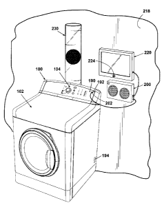
The various connections among the appliance 100, the smart device 200, and
the demo devices 220, 230 can be seen in Figure 12. The smart device 200 is
connected to the dryer 100 by plugging the USB device 202 into the USB port
192 on
the dryer 100. Once the smart device 200 is plugged in 304, the dryer 100
operates in
a passive mode, and the smart device 200 assumes complete control of the dryer
100
to present a sales demo 240.
Looking now also at Figure 13, the smart device 200 automatically powers up
the dryer 100 upon being plugged in 304 and begins operation in an active
sales demo
mode 302, which will be discussed in more detail hereinafter. It is noted that
the
dryer 100 will be connected to a source of power sufficient to operate the
blower 140.
That source may be the smart device 200 itself or an independent source. The
smart
camera 224 and the user interface 104 on the dryer 100 continuously perform a
check
243 for the presence 246 of customers throughout the entire sales demo 240.
The
smart camera 224 continuously searches for customers within a certain distance
of the
CA 02614954 2007-12-14
dryer 100. The user interface 104 also waits for and receives any input
received from
the customer. Customer presence 246 is detected through the manipulation of
power
button 148, dial 152, parameter adjusting buttons 154, start button 160, stop
button
162, first parameter selection button 166, second parameter selection button
170, or
on/off buttons 178, or by way of the smart camera 224 detecting a customer in
close
proximity to the dryer 100
The smart camera 224 can identify certain characteristics of customers using
embedded software, such as approximate age and gender. The smart camera 224
can
store records of these characteristics. The smart camera 224 can provide this
information to the smart device 200 to enable to the smart device 200 to
tailor the
sales demo 240 to suit a particular customer. An example of such tailoring is
targeting male and female customers separately by interchangeably presenting
two
demos using two different color schemes. One color scheme has been developed
to
elicit a more positive response from females, and one color scheme has been
developed to elicit a more positive response from males. Other examples could
include, but are not limited to, using different types of music, using
different voices,
using different advertising concepts, and highlighting different features.
If no customers are detected 244 within a certain distance of the dryer for a
predetermined length of time specified by the sales demo 240, the smart device
200
switches the dryer 100 into a default sales demo mode 300. If a customer
presence
246, the smart device 200 will switch the dryer 100 back to the active sales
demo
mode 302. The default sales mode 300 will also run if a customer presses 248
the
stop button 162 at any time during the active mode 302.
In the default sales demo mode 300, the smart device 200 operates the dryer
100 to present a light show 306 using the dryer status indicator lights 150,
the first set
of indicator lights 168, the second set of indicator lights 172, and the
on/off indicator
lights 180. The various lights are turned on and off to produce a number of
visually-
stimulating patterns. The smart device 200 also operates the digital display
156 to
output a variety of displays 308 designed to draw the attention of potential
customers,
such as a greeting or an aesthetically pleasing pattern. The smart device 200
can
operate the LCD monitor 220 to display a variety of promotional offers 309,
advertisements 310, and the like. One example would be displaying the text,
"20%
off, today only," accompanied by eye-catching graphics depicting the dryer
100. The
smart device 200 can operate the speakers 216 to output an invitational voice
clip 314
16
CA 02614954 2007-12-14
inviting customers to interact with the dryer 100 as well. An example of such
an
invitational voice clip 314 could be an inviting phrase reciting "please press
any
button to learn about our featured dryer".
If the user interface 104 detects that a customer presence 246, the smart
device
200 will respond by converting to the active mode 302. The smart device 200
will
first output an introductory voice clip 320 through speaker 216. The
introductory
voice clip 320 will comprise voice instructions inviting the customer to turn
the dial
152 or press one of the buttons to learn about each feature of the dryer. The
introductory voice clip 320 will also invite the customer to press the start
button 160
to learn about the special drying air flow feature of the dryer 100. The
introductory
voice clip 320 includes instructions informing the customer that the stop
button 162
can be pressed at any time to exit the dryer demonstration.
If a customer presses one of the buttons 148, 160, 162, 166, 170, 178, the
smart device 200 will output a feature-specific voice clip 322 through the
speaker
216. For example, if an on/off button 178 if pressed and the button 178 has
indicia
indicating it functions to turn a drying chamber light on and off, a feature-
specific
voice clip 322 could be played that says, "The light feature will allow you to
view the
contents of the dryer without halting dryer operation." Throughout the active
mode
302, the LCD monitor 220 also displays various video clips 324 to support the
feature-specific voice clips 322. For example, as the speakers 216 output a
voice
saying "the light feature will allow you to view the contents of the dryer
without
halting dryer operation," the LCD monitor 220 will show a video clip 324 of
the light
turning on and off while a number of clothing items are tumbling about the
drying
chamber.
In addition, the smart device 200 can operate the various components of the
dryer 100 to further the quality of the sales demo 240 by providing a
component
demonstration 326. The component demonstration 326 can comprise operation of
one
or more internal components of the dryer 100 in order to demonstrate dryer
operation.
For example, in conjunction with the light-related feature-specific voice clip
322 and
video clips 324 discussed above, the smart device 200 could instruct a
component
responsible for operating the light in the dryer 100 to switch the light on
and off.
If a customer presses the start button 160, the air flow demo unit 230 can be
used to present an air flow demo unit demonstration 330. The blower assembly
140
will be operated by the smart device 200 to produce varying rates of air flow
in order
17
CA 02614954 2007-12-14
to demonstrate the dryer's 100 unique air flow feature. The air will flow out
the
exhaust and into the conduit 232 to cause the ba11234 to move upwardly and
downwardly in the conduit 232. The other components of the dryer 100 that
would
operate during normal operation of the dryer 100 will not be operated, such as
the
heater assembly 144 and the motor assembly 133. The blower assembly 140 will
produce varying air flow rates will cause the ball to hover near the top of
the conduit
232, at a point just above the user interface 104 so that a customer can still
see the ball
234, and at a point therebetween. As the ball 234 is moved about, an air flow
voice
clip 334 will be emitted via speakers 216 that will explain the benefits of
varying the
air flow. The LCD monitor 220 can also display a corresponding air flow video
clip
336 of a graph depicting the improved drying ability of the dryer 100 as
compared to
competitor's dryers. Upon completion of the air flow demo unit demonstration
330,
the introductory voice clip 320 can be output by the speakers 216 once again.
The smart device 200 can be disconnected 337 from the dryer 100 at any time
to halt operation 338 of the sales demo 240.
Looking now also at Fig. 14, a production unit of the dryer 100 having the
capability to perform part or all of the aforementioned functions, depending
upon
model, is shipped by its manufacturer 196 to a vendor 198 for sale. Once at
the
vendor 198, the dryer 100 is put on display at a desired location where
customers can
walk about and view the dryer 100. The dryer 100 may be plugged into a power
source, enabling it to be operated to the fullest extent of its capabilities,
but more
commonly, it will not be connected to a conventional power source. Here is
where
the invention is most useful.
Various sales demos 240 stored in the smart device 200 can be accessed and
updated by connecting a computer 340 having a USB device 342 to USB port 210
of
the smart device 200. Alternatively, the computer 340 can comprise a wireless
device
(not shown) and can be connected wirelessly to the smart device 200 via
wireless port
212. This is simply a matter of preference and/or availability for each
particular
vendor 198 displaying the dryer 100. New sales demos 240 and sales demo
updates
360 can also be downloaded via the computer 340. Existing sales demos 240 can
be
updated, modified, or deleted via the computer 340. The computer 340 comprises
a
connection to the internet 346 enabling access to a website 350. The website
350 is
managed by either the manufacturer 196 or the vendor 198. The website 350
comprises a database 354 having a variety of sales demos 240 and/or sales demo
18
CA 02614954 2007-12-14
updates 360 that can be downloaded to the smart device 200 using a specially-
designed downloading program 352 installed on the computer 340. The
downloading
program 352 software can be downloaded from the website 350. The program 352
provides a simple interface or window serving to guide a user through the
downloading process. The program 352 downloads the sales demos 240 to the
smart
device 200. The program 352 can also enable a user to modify certain
characteristics
of the sales demo 240. Modifiable characteristics can be designated within the
sales
demo 240 code.
The sales demos 240 can be downloaded to the smart device 200 and altered
as previously described, which enables the vendor 198 to adapt the sales demos
240 to
suit current business needs. Different sales demos 240 are available so as to
enable
vendors 198 to adapt the sales demos 240 for incorporation of a variety of
business
concepts 366 as shown in Figure 15.
Business concepts 366 can include targeting regions 370, incorporating
advertising campaigns 372, targeting demographics 374, reflecting marketing
strategies 376, and/or including current promotions 378. The target region 370
and
target demographic 374 are commonly designated by the vendor 198, as
manufacturers 196 tend to supply appliances to numerous regions 370 and
demographics 374. The advertising campaigns 372, marketing strategies 376, and
current promotions 378 can be those of either the manufacturer 196 or the
vendor 198.
By differentiating the dryer 100 from other dryers on display at the vendor
198, the
sales demos 240 can help improve sales of the dryer 100. The sales demos 240
can be
customized according to the vendor 198 and trade partners of the manufacturer
196 of
the dryer 100. Furthermore, by locating the sales demos 240 on the smart
device 200,
code for sales demos 240 that would traditionally reside on the dryer 100 can
be
removed from the dryer 100, thereby reducing development time and cost of the
dryer
100. In addition, information gathered and stored by the smart camera 224 and
the
user interface 104 can be accessed by the manufacturer 196 and/or vendor 198
to
generate customer profiles 380. Customer profiles 380 can then be used to
generate
advertising campaigns 372, marketing strategies 376, and the like.
It will be apparent from this disclosure that a manufacturer need only make
production units of a product and offer them for sale through normal
distribution
channels. The invention provides a very flexible way to demonstrate the
product by
enabling a vendor to connect the smart device to a given production unit,
install
19
CA 02614954 2007-12-14
specific demonstration software on the smart device, and operate the smart
device to
assume control of the product in a demonstration mode. The sales demonstration
can
thus be targeted to a specific market, for example, geographically or
demographically.
The demonstration can be tailored to a specific vendor by simple software
changes. It
can be made fully interactive with a potential customer, and even tailored to
the type
of customer that the system might be configured to perceive.
While the invention has been specifically described in connection with certain
specific embodiments thereof, it is to be understood that this is by way of
illustration
and not of limitation. Reasonable variation and modification are possible
within the
scope of the forgoing disclosure and drawings without departing from the
spirit of the
invention which is defined in the appended claims.