Language selection

Search

Patent 2615016 Summary

Third-party information liability

Some of the information on this Web page has been provided by external sources. The Government of Canada is not responsible for the accuracy, reliability or currency of the information supplied by external sources. Users wishing to rely upon this information should consult directly with the source of the information. Content provided by external sources is not subject to official languages, privacy and accessibility requirements.

Claims and Abstract availability

Any discrepancies in the text and image of the Claims and Abstract are due to differing posting times. Text of the Claims and Abstract are posted:

  • At the time the application is open to public inspection;
  • At the time of issue of the patent (grant).
(12) Patent Application: (11) CA 2615016
(54) English Title: LASER GRAVITATIONAL FIELD FLUCTUATION DETECTOR
(54) French Title: DETECTEUR LASER DE FLUCTUATIONS DU CHAMP GRAVITATIONNEL
Status: Dead
Bibliographic Data
(51) International Patent Classification (IPC):
  • G01V 7/00 (2006.01)
(72) Inventors :
  • ERDMANN, ERICH (Canada)
  • ERDMANN, ADOLT (Canada)
(73) Owners :
  • ERDMANN, ERICH (Canada)
  • ERDMANN, ADOLT (Canada)
(71) Applicants :
  • ERDMANN, ERICH (Canada)
  • ERDMANN, ADOLT (Canada)
(74) Agent: NA
(74) Associate agent: NA
(45) Issued:
(22) Filed Date: 2007-12-17
(41) Open to Public Inspection: 2009-06-17
Availability of licence: N/A
(25) Language of filing: English

Patent Cooperation Treaty (PCT): No

(30) Application Priority Data: None

Abstracts

English Abstract


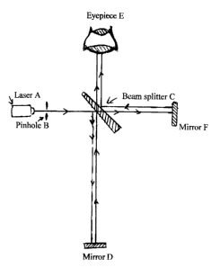
The Laser Gravitational Field Fluctuation Detector is designed to detect
gravitational
fluctuations in the Earth's gravitational field as for example when the Earth
is influenced
by the Sun or Moon's gravitation field which results in ocean tides. This
detection is
accomplished by measuring the deviation of two light beams from their normal
paths in
reference to each other when subjected to a gravitational field, due to the
fact that a
perpendicular beam is affected differently than a parallel beam. Both beams
having been
created from a single beam by means of a narrow angle glass prism beam
splitter are
affected each differently by the gravitational field. Fluctuation detection is
accomplished
by recombining both beams by means of two mirrors and the beam splitter in
order to
produce a bull`s eye type of interference pattern which can be viewed through
the eyepiece
and also recorded through the eyepiece by a camera or photocell.


Claims

Note: Claims are shown in the official language in which they were submitted.


Claims:


"The embodiments of the invention in which an exclusive property or privilege
is claimed
are defined as follows."


1. A device for the use of measuring fluctuations in the Earth's gravitational
field or
others such as from the Sun or Moon in order to assist in earthquake
detection, said
device comprising a monochromatic light source such as from a laser, a metal
plate with a
small pinhole in it, a narrow glass prism as beam splitter, two regular
mirrors, an
eyepiece, an electronic camera and a support structure.


2. The device described in claim 1 operates on the principle that
gravitational fields affect
light, such as bending or distorting its regular path. Due to the fact that
the beams are at
different angles to the direction of the Earth's gravitational field, one
being parallel and
the other perpendicular in relation to it, they are affected unequally
resulting in a drift in
the interference pattern after they have been recombined, the pattern is
similar in nature to
that produced by Young's pinhole experiment.


3. The device as described in claim 1 and claim 2 is based on scientific
evidence obtained
by modern astronomy, such as the fact that gravitational fields from collapsed
stars
known as black holes distort the view of objects such as galaxies behind them
by bending
the light paths around them.


Description

Note: Descriptions are shown in the official language in which they were submitted.


CA 02615016 2007-12-17
Disclosure.

The principle of operation is quite simple, the laser beam first passes
through the pinhole
which creates a pinpoint light source and also spreads the light out to some
degree. The
light is then diverted into two beams by the glass prism beam splitter which
prevents
closely spaced unwanted double images, each beam is then reflected by a mirror
and
returned to the beam splitter which directs it into the eyepiece, such as from
a microscope
or binoculars, where it can be viewed or photographed.
The alignment is done by first removing the eyepiece, and then looking
directly into
the beam which is not hannful since its intensity has been reduced by the
small pinhole
and also further reduced by being reflected of the glass surface of the beam
splitter prism,
the system is then aligned. What normally is seen are two bright red dots of
light in the
same vicinity.
By adjusting the angles of the mirrors and the bearn splitter the two dot have
to be
brought to coincide so that they will appear as one dot, although the dots
being sliglitly
apart in any direction will also works, but this produces a different
interference pattern of
parallel lines perpendicular to the direction of the dots. The distance from
one mirror to
the beam splitter has to be slightly longer than the distance to the other
mirror in order to
produce the concentric rings once the eyepiece has been put back. The pattern
of rings
can be viewed or photographed or recorded by a computer with a computer
camera.
Fluctuations in the Earth's gravitational field will show up in a manner that
the rings from
time to time for no apparent reason move towards the centre or away from it,
as well as

1


CA 02615016 2007-12-17
the entire pattern may'also shift.
Any similarities with the Michelson interferometer designed to measure the
Earth's
motion through space or the Twyman-Green interferometer designed to detect any
unevenness in optical surfaces as well as laser holography is, except for the
basic
principles of light interference, purely coincidental after all our device
detects fluctuations
in the Earth's gravitational field which is different from the purpose of all
the others
which also employ the basic principle of light interference.
We believe that the magma at the centre of the Earth rotates faster than the
Earth
itself and al so at an angle to the Earth's axis and causes the tectonics
plates floating on
the molten lava to drift, the rotation also produces the Earth's magnetic
fieI.d, it may be
Eddies which produce gravitational fluctuations that may result from time to
time into
earthquakes.

Fig. 2 When the instrument is correctly positioned fluctuations in the Earth's
gravitational
field will cause the interference pattern rings to either drift outward or
inward. Tilting the
instrument will also cause a drift of the patterns. These patterns were
produce by tilting
the instrument in order to show a more precise pattern as can be seen that the
center can
vary between bright and dark while the rings around it become larger or
smaller. In other
words the rings originate from the center or vanish into the center.

Description of how it works.
As shown in Fig. 3 the light from the laser A is first directed to the metal
plate B
with the small pinhole in it, after having passed through. it, the light is
then reflected by
the glass surface of the narrow angle prism C vertically downward to mirror D
from
where it is reflected back upward passing through prism C into eyepiece E.
The light from laser A will also, after having passed through the pinhole in
metal
plate B, pass through prism C and is then reflected off mirror F and returns
to prism C
from where it is reflected and also directed into eyepiece E where it combines
with the
other beam to form an interference pattern that can be seen with the eye or
recorded with
a camera as shown in Fig. 2 or with a photosensitive device to produce a
graph.

2

Representative Drawing
A single figure which represents the drawing illustrating the invention.
Administrative Status

For a clearer understanding of the status of the application/patent presented on this page, the site Disclaimer , as well as the definitions for Patent , Administrative Status , Maintenance Fee  and Payment History  should be consulted.

Administrative Status

Title Date
Forecasted Issue Date Unavailable
(22) Filed 2007-12-17
(41) Open to Public Inspection 2009-06-17
Dead Application 2013-12-17

Abandonment History

Abandonment Date Reason Reinstatement Date
2012-12-17 FAILURE TO REQUEST EXAMINATION
2012-12-17 FAILURE TO PAY APPLICATION MAINTENANCE FEE

Payment History

Fee Type Anniversary Year Due Date Amount Paid Paid Date
Application Fee $200.00 2007-12-17
Maintenance Fee - Application - New Act 2 2009-12-17 $50.00 2009-12-14
Maintenance Fee - Application - New Act 3 2010-12-17 $50.00 2010-10-04
Maintenance Fee - Application - New Act 4 2011-12-19 $50.00 2011-10-18
Owners on Record

Note: Records showing the ownership history in alphabetical order.

Current Owners on Record
ERDMANN, ERICH
ERDMANN, ADOLT
Past Owners on Record
None
Past Owners that do not appear in the "Owners on Record" listing will appear in other documentation within the application.
Documents

To view selected files, please enter reCAPTCHA code :


To view images, click a link in the Document Description column. To download the documents, select one or more checkboxes in the first column and then click the "Download Selected in PDF format (Zip Archive)" or the "Download Selected as Single PDF" button.

List of published and non-published patent-specific documents on the CPD .

If you have any difficulty accessing content, you can call the Client Service Centre at 1-866-997-1936 or send them an e-mail at CIPO Client Service Centre.


Document
Description 
Date
(yyyy-mm-dd) 
Number of pages   Size of Image (KB) 
Abstract 2007-12-17 1 24
Description 2007-12-17 2 97
Claims 2007-12-17 1 34
Drawings 2007-12-17 2 28
Representative Drawing 2008-11-13 1 4
Cover Page 2009-06-12 2 39
Assignment 2007-12-17 4 133
Correspondence 2008-04-22 1 14
Fees 2009-12-14 1 25
Correspondence 2009-12-14 2 84
Fees 2010-10-04 1 14
Fees 2011-10-18 1 13