Note: Descriptions are shown in the official language in which they were submitted.
CA 02615068 2007-12-10
1 -
RADIATION AND MELT TREATED ULTRA HIGH MOLECULAR WEIGHT
POLYETHYLENE PROSTHETIC DEVICES
This is a division of Canadian Patent Application No. 2,246,342.
FIELD OF THE INVENTION
The present invention relates to the orthopedic field and
the provision of prostheses, such as hip and knee implants, as
well as methods of manufacture of such devices and material used
therein.
BACKGROUND OF THE INVENTION
The use of synthetic polymers, e.g., ultra high molecular
weight polyethylene, with metallic alloys has revolutionized the
field of prosthetic implants, e.g., their use in total joint
replacements for the hip or knee. Wear of the synthetic polymer
against the metal of the articulation, however, can result in
severe adverse effects which predominantly manifest after
several years. Various studies have concluded that such wear
can lead to the liberation of ultrafine particles of
polyethylene into the periprosthetic tissues. It has been
suggested that the abrasion stretches the chain folded
crystallites to form anisotropic fibrillar structures at the
articulating surface. The stretched-out fibrils can then
rupture, leading to production of submicron sized particles. In
response to the progressive ingress of these polyethylene
particles between the prosthesis and bone, macrophage-induced
resorption of the periprosthetic bone is initiated. The
macrophage, often being unable to digest these polyethylene
particles, synthesize and release large numbers of cytokines and
growth factors which can ultimately result in bone resorption by
osteoclasts and monocytes. This osteolysis can contribute to
mechanical loosening of the prosthesis components, thereby
sometimes requiring revision surgery with its concomitant
problems.
CA 02615068 2011-09-01
31676-6D
2
Summary of the Invention
It is an object of the invention to provide an implantable prosthesis device
formed at least in part of radiation treated ultra high molecular weight
polyethylene
(UHMWPE) having no detectable free radicals, so as to reduce production of
fine particles
from the prosthesis during wear of the prosthesis.
It is another object of the invention to reduce osteolysis and inflammatory
reactions resulting from prosthesis implants.
It is yet another object of the invention to provide a prosthesis which can
remain implanted within a person for prolonged periods of time.
It is yet another object of the invention to provide improved UHMWPE which
can be used in the prostheses of the preceding objects and/or in other
fabricated articles.
Still another object of the invention is to provide improved UHMWPE which
has a high density of cross-links and no detectable free radicals.
A still further object of the invention is to provide improved UHMWPE which
has improved wear resistance.
In one aspect, the present invention relates to a preformed material for
subsequent production of a wear resistant medical implant comprising a cross-
linked
consolidated Ultra High Molecular Weight Polyethylene (UHMWPE) produced by a
method
comprising the steps of: (a) irradiating consolidated UHMWPE to cross-link
UHMWPE
molecules; (b) ceasing irradiation of the consolidated UHMWPE, wherein the
temperature of
the consolidated UHMWPE is above room temperature; (c) repeating steps (a) and
(b) at
least once to obtain a total absorbed radiation dose of about 5 to about 100
MRad; and (d)
allowing the cross-linked consolidated UHMWPE to cool to room temperature.
In another aspect, the present invention relates to a medical device
comprising a Ultra High Molecular Weight Polyethylene (UHMWPE) material
produced by a
method comprising the steps of: (a) irradiating consolidated
CA 02615068 2010-08-20
31676-6D
- 2a -
UHMWPE to cross-link UHMWPE molecules; (b) ceasing irradiation of the
consolidated UHMWPE, wherein the temperature of the consolidated UHMWPE is
lower than the melting point of the UHMWPE material; (c) repeating steps (a)
and
(b) at least once to obtain a total absorbed radiation dose of about 5 to
about 100
MRad; and (d) allowing the cross-linked consolidated UHMWPE to cool to room
temperature.
In another aspect, the present invention relates to a method for
increasing the wear resistance of a preformed consolidated Ultra High
Molecular
Weight Polyethylene (UHMWPE) comprising the steps of: (a) irradiating the
preformed consolidated UHMWPE in the solid state to cross-link UHMWPE
molecules; (b) ceasing irradiation of the consolidated UHMWPE, wherein the
temperature of the consolidated UHMWPE is above room temperature and below
the melting point of the UHMWPE; (c) repeating steps (a) and (b) at least once
to
obtain a total absorbed dose of about 5 to about 100 MRad; and (d) allowing
the
consolidated UHMWPE to cool to room temperature.
According to the invention, a medical prosthesis for use within the
body which is formed of radiation treated ultra high molecular weight
polyethylene
(UHMWPE) having substantially no detectable free radicals, is provided. The
radiation can be, e.g., gamma or electron radiation. The UHMWPE has a
cross-linked structure. Preferably, the UHMWPE is substantially not oxidized
and
is substantially oxidation resistant. Variations include, e.g., the UHMWPE
having
three melting peaks, two melting peaks or one melting peak. In certain
embodiments, the UHMWPE has a polymeric structure with less than about 50%
crystallinity, less than about 290A lamellar thickness and less than about 940
MPa
tensile elastic modulus, so as to reduce production of fine particles from the
prosthesis during wear of the prosthesis. Part of the prosthesis can be, e.g.,
in the
form of a cup or tray shaped article having a load bearing surface made of
this
UHMWPE. This load bearing surface can be in contact with a second part of the
prosthesis having a mating load bearing surface of a metallic or ceramic
material.
Another aspect of the invention is radiation treated UHMWPE
CA 02615068 2007-12-10
-3-
having substantially no detectable free radicals. This UHMWPE
has a cross-linked structure. Preferably, this UHMWPE is
substantially not oxidized and is substantially oxidation
resistant. Variations include, e.g., the UHMWPE having three
melting peaks, two melting peaks or one melting peak.
Other aspects of the invention are fabricated articles,
e.g., with a load bearing surface, and wear resistant coatings,
made from such UHMWPE. One embodiment is where the fabricated
article is in the form of a bar stock which is capable of being
io shaped into articles by conventional methods, e.g., machining.
Yet another aspect of the invention includes a method for
making a cross-linked UHMWPE having substantially no detectable
free radicals. Conventional UHMWPE having polymeric chains is
provided. This UHMWPE is irradiated so as to cross-link said
polymeric chains. The UHMWPE is heated above the melting
temperature of the UHMWPE so that there are substantially no
detectable free radicals in the UHMWPE. The UHMWPE is then
cooled to room temperature. In certain embodiments, the cooled
UHMWPE is machined and/or sterilized.
One preferred embodiment of this method is called CIR-SM,
i.e., cold irradiation and subsequent melting. The UHMWPE that
is provided is at room temperature or below room temperature.
Another preferred embodiment of this method is called
WIR-SM, i.e., warm irradiation and subsequent melting. The
UHMWPE that is provided is pre-heated to a temperature below the
melting temperature of the UHMWPE.
Another preferred embodiment of this method is called
WIR-AM, i.e., warm irradiation and adiabatic melting. In this
embodiment, the UHMWPE that is provided is pre-heated to a
temperature below the melting temperature of the UHMWPE,
preferably between about 100 C to below the melting temperature
of the UHMWPE. Preferably, the UHMWPE is in an insulating
material so as to reduce heat loss from the UHMWPE during
processing. The pre-heated UHMWPE is then irradiated to a high
enough total dose and at a fast enough dose rate so as to
generate enough heat in the polymer to melt substantially all
the crystals in the material and thus ensure elimination of
substantially all detectable free radicals generated by, e.g.,
the irradiating step. It is preferred that the irradiating step
CA 02615068 2007-12-10
-4-
use electron irradiation so as to generate such adiabatic
heating.
Another aspect of this invention is the product made in
accordance with the above described method.
Yet another aspect of this invention, called MIR, i.e.,
melt irradiation, is a method for making crosslinked UHMWPE.
Conventional UHMWPE is provided. Preferably, the UHMWPE is
surrounded with an inert material that is substantially free of
oxygen. The UHMWPE is heated above the melting temperature of
to the UHMWPE so as to completely melt all crystalline structure.
The heated UHMWPE is irradiated, and the irradiated UHMWPE is
cooled to about 25 C.
In an embodiment of MIR, highly entangled and crosslinked
UHMWPE is made. Conventional UHMWPE is provided. Preferably,
the UHMWPE is surrounded with an inert material that is
substantially free of oxygen. The UHMWPE is heated above the
melting temperature of the UHMWPE for a time sufficient to
enable the formation of entangled polymer chains in the UHMWPE.
The heated UHMWPE is irradiated so as to trap the polymer chains
in the entangled state, and the irradiated UHMWPE is cooled to
about 25 C.
The invention also features a method of making a medical
prosthesis from radiation treated UHMWPE having substantially no
detectable free radicals, the prosthesis resulting in reduced
production of particles from the prosthesis during wear of the
prosthesis. Radiation treated UHMWPE having no detectable free
radicals is provided. A medical prosthesis is formed from this
UHMWPE so as to reduce production of particles from the
prosthesis during wear of the prosthesis, the UHMWPE forming a
load bearing surface of the prosthesis. Formation of the
prosthesis can be accomplished by standard procedures known to
those skilled in the art, e.g., machining.
Also provided in this invention is a method of treating a
body in need of a medical prosthesis. A shaped prosthesis
formed of radiation treated UHMWPE having substantially no
detectable free radicals is provided. The prosthesis is applied
to the body in need of the prosthesis. The prosthesis reduces
production of particles from the prosthesis during wear of the
prosthesis. In preferred embodiments, the UHMWPE forms a load
CA 02615068 2007-12-10
-5-
bearing surface of the prosthesis.
The above and other objects, features and advantages of the
present invention will be better understood from the following
specification when read in conjunction with the accompanying
drawings.
Brief Description of the Drawings
FIG. 1 is a cross-sectional view through the center of a
medical hip joint prosthesis in accordance with a preferred
1o embodiment of"this invention;
FIG. 2 is a side view of an acetabular cup liner as shown
in FIG. 1;
FIG. 3 is a cross-sectional view through line 3-3 of FIG.
2;
FIG. 4 is a graph showing the crystallinity and melting
point of melt-irradiated UHMWPE at different irradiation doses;
FIG. 5 is an environmental scanning electron micrograph of
an etched surface of conventional UHMWPE showing its crystalline
structure;
FIG. 6 is an environmental scanning electron micrograph of
an etched surface of melt-irradiated UHMWPE showing its
crystalline structure at approximately the same magnification as
in FIG. 5; and
FIG. 7 is a graph showing the crystallinity and melting
point at different depths of a melt-irradiated UHMWPE cup.
FIG. 8 is a graph showing DSC melting endotherms for
Hoechst-Celanese GUR 4050 UHMWPE prepared using warm irradiation
and partial adiabatic melting (WIR-AM), with and without
subsequent heating.
FIG. 9 is a graph showing DSC melting endotherms for
Hoechst-Celanese GUR 1050 UHMWPE prepared using warm irradiation
and partial adiabatic melting (WIR-AN), with and without
subsequent heating.
FIG. 10 is a graph showing adiabatic heating of UHMWPE
treated by WIR-AM with a pre-heat temperature of 130 C.
FIG. 11 is a graph showing tensile deformation behavior of
unirradiated UHMWPE, CIR-SM treated UHMWPE, and WIR-AM treated
UHMWPE.
CA 02615068 2007-12-10
-6-
Detailed Description
This invention provides a medical prosthesis for use within
the body which is formed of radiation treated ultra high
molecular weight polyethylene (UHMWPE) which has substantially
s no detectable free radicals.
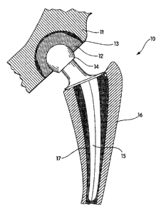
A medical prosthesis in the form of a hip joint prosthesis
is generally illustrated at 10 in FIG. 1. The prosthesis shown
has a conventional ball head 14 connected by a neck portion to a
stem 15 which is mounted by conventional cement 17 to the femur
l0 16. The ball head can be of conventional design and formed of
stainless steel or other alloys as known in the art. The radius
of the ball head closely conforms to the inner cup radius of an
acetabular cup 12 which can be mounted in cement 13 directly to
the pelvis 11. Alternatively, a metallic acetabular shell can
is be cemented to the pelvis 11 and the acetabular cup 12 can form
a coating or liner connected to the metallic acetabular shell by
means as are known in the art.
The specific form of the prosthesis can vary greatly as
known in the art. Many hip joint constructions are known and
20 other prostheses such as knee joints, shoulder joints, ankle
joints, elbow joints and finger joints are known. All such
prior art prostheses can be benefited by making at least one
load bearing surface of such prosthesis of a high molecular
weight polyethylene material in accordance with this invention.
25 Such load bearing surfaces can be in the form of layers, linings
or actual whole devices as shown in FIG. 1. In all cases, it is
preferred that the load bearing surface act in conjunction with
a metallic or ceramic mating member of the prosthesis so that a
sliding surface is formed therebetween. Such sliding surfaces
3o are subject to breakdown of the polyethylene as known in the
prior art. Such breakdown can be greatly diminished by use of
the materials of the present invention.
FIG. 2 shows the acetabular cup 12 in the form of a half
hollow ball-shaped device better seen in the cross-section of
35 FIG. 3. As previously described, the outer surface 20 of the
acetabular cup need not be circular or hemispherical but can be
square or of any configuration to be adhered directly to the
pelvis or to the pelvis through a metallic shell as known in the
art. The radius of the acetabular cup shown at 21 in FIG. 3 of
CA 02615068 2007-12-10
-7-
the preferred embodiment ranges from about 20 mm to about 35 mm.
The thickness of the acetabular cup from its generally
hemispherical hollow portion to the outer surface 20 is
preferably about 8 mm. The outer radius is preferably in the
order of about 20 mm to about 35 mm.
In some cases, the ball joint can be made of the UHMWPE of
this invention and the acetabular cup formed of metal, although
it is preferred to make the acetabular cup or acetabular cup
liner of UHMWPE to mate with the metallic ball. The particular
io method of attachment of the components of the prosthesis to the
bones of the body can vary greatly as known in the art.
The medical prosthesis of this invention is meant to
include whole prosthetic devices or portions thereof, e.g., a
component, layer or lining. The medical prosthesis includes,
is e.g., orthopedic joint and bone replacement parts, e.g., hip,
knee, shoulder, elbow, ankle or finger replacements. The
prosthesis can be in the form, e.g., of a cup or tray shaped
article which has a load bearing surface. Other forms known to
those skilled in the art are also included in the invention.
20 Medical prostheses are also meant to include any wearing surface
of a prosthesis, e.g., a coating on a surface of a prosthesis in
which the prosthesis is made from a material other than the
UHMWPE of this invention.
The prostheses of this invention are useful for contact
25 with metal containing parts formed of, e.g., cobalt chromium
alloy, stainless steel, titanium alloy or nickel cobalt alloy,
or with ceramic containing parts. For example, a hip joint is
constructed in which a cup shaped article having an inner radius
of 25 mm, is contacted with a metal ball having an outer radius
30 of 25 mm, so as to closely mate with the cup shaped article.
The load bearing surface of the cup shaped article of this
example is made from the UHMWPE of this invention, preferably
having a thickness of at least about 1 mm, more preferably
having a thickness of at least about 2 mm, more preferably
3s having a thickness of at least about 1/4 inch, and more preferably
yet having a thickness of at least about 1/3 inch.
The prostheses can have any standard known form, shape, or
configuration, or be a custom design, but have at least one load
bearing surface of UHMWPE of this invention.
CA 02615068 2010-08-20
31676-6D
-8-
The prostheses of this invention are non-toxic to humans.
They are not subject to deterioration by normal body
constituents, e.g., blood or interstitial fluids. They are
capable of being sterilized by standard means, including, e.g.,
s heat or ethylene oxide.
By UHMWPE is meant linear non-branched chains of ethylene
that have molecular weights in excess of about 500,000,
preferably above about 1,000,000, and more preferably above
about 2,000,000. Often the molecular weights can be at least as
io high as about 8,000,000. By initial average molecular weight is
meant the average molecular weight of the UHMWPE starting
material, prior to any irradiation.
Conventional UHMWPE is standardly generated by
Ziegler-Natta catalysis, and as the polymer chains are generated
15 from the surface catalytic site, they crystallize, and interlock
as chain folded crystals. Examples of known UHMWPE powders
include Hifax*Grade 1900 polyethylene (obtained from Montell,
Wilmington, Delaware), having a molecular weight of about 2
million g/mol and not containing any calcium stearate; GUR*4150,
20 also known as GUR 415, (obtained from Hoescht Celanese Corp.,
Houston, TX), having a molecular weight of about 4-5 million
g/mol and containing 500 ppm of calcium stearate; GUR 4050
(obtained from Hoescht Celanese Corp., Houston, TX), having a
molecular weight of about 4-5 million g/mol and not containing
25 any calcium stearate; GUR 4120 (obtained from Hoescht Celanese
Corp., Houston, TX), having a molecular weight of about 2
million g/mol and containing 500 ppm of calcium stearate; GUR
4020 (obtained from Hoescht Celanese Corp., Houston, TX), having
a molecular weight =of about 2 million g/mol and not containing
30 any calcium stearate; GUR 1050 (obtained from Hoescht Celanese
Corp., Germany), having a molecular weight of about 4-5 million
g/mol and not containing any calcium stearate; GUR 1150
(obtained from Hoescht Celanese Corp., Germany), having a
molecular weight of about 4-5 million g/mol and containing 500
35 ppm of calcium stearate; GUR 1020 (obtained from Hoescht
Celanese Corp., Germany), having a molecular weight of about 2
million g/mol and not containing any calcium stearate; and GUR
1120 (obtained from Hoescht Celanese Corp., Germany), having a
molecular weight of about 2 million g/mol and containing 500 ppm
*TRADE-MARK
CA 02615068 2007-12-10
-9-
of calcium stearate. Preferred UHMWPEs for medical applications
are GUR 4150, GUR 1050 and GUR 1020. By resin is meant powder.
UHMWPE powder can be consolidated using a variety of
different techniques, e.g., ram extrusion, compression molding
or direct compression molding. In ram extrusion, the UHMWPE
powder is pressurized through a heated barrel whereby it is
consolidated into a rod stock, i.e., bar stock (can be obtained,
e.g., from Westlake Plastics, Lenni, PA). In compression
molding, the UHMWPE powder is consolidated under high pressure
io into a mold (can be obtained, e.g., from Poly-Hi Solidur, Fort
Wayne, IN, or Perplas, Stanmore, U.K.). The shape of the mold
can be, e.g., a thick sheet. Direct compression molding is
preferably used to manufacture net shaped products, e.g.,
acetabular components or tibial knee inserts (can be obtained,
e.g., from Zimmer, Inc., Warsaw, IN). In this technique, the
UHMWPE powder is compressed directly into the final shape.
"Hockey pucks", or pucks, are generally machined from ram
extruded bar stock or from a compression molded sheet.
By radiation treated UHMWPE is meant UHMWPE which has been
treated with radiation, e.g., gamma radiation or electron
radiation, so as to induce cross-links between the polymeric
chains of the UHMWPE.
By substantially no detectable free radicals is meant
substantially no free radicals as measured by electron
paramagnetic resonance, as described in Jahan et al., J.
Biomedical Materials Research 25:1005 (1991). Free radicals
include, e.g., unsaturated trans-vinylene free radicals. UHMWPE
that has been irradiated below its melting point with ionizing
radiation contains cross-links as well as long-lived trapped
free radicals. These free radicals react with oxygen over the
long-term and result in the embrittlement of the UHMWPE through
oxidative degradation. An advantage of the UHMWPE and medical
prostheses of this invention is that radiation treated UHMWPE is
used which has no detectable free radicals. The free radicals
can be eliminated by any method which gives this result, e.g.,
by heating the UHMWPE above its melting point such that
substantially no residual crystalline structure remains. By
eliminating the crystalline structure, the free radicals are
able to recombine and thus are eliminated.
CA 02615068 2007-12-10
-10-
The UHMWPE which is used in this invention has a
cross-linked structure. An advantage of having a cross-linked
structure is that it will reduce production of particles from
the prosthesis during wear of the prosthesis.
s It is preferred that the UHMWPE be substantially not
oxidized. By substantially not oxidized is meant that the ratio
of the area under the carbonyl peak at 1740 cml in the FTIR
spectra to the area under the peak at 1460 cm'' in the FTIR
spectra of the cross-linked sample be of the same order of
io magnitude as the ratio for the sample before cross-linking.
It is preferred that the UHMWPE be substantially oxidation
resistant. By substantially oxidation resistant is meant that
it remains substantially not oxidized for at least about 10
years. Preferably, it remains substantially not oxidized for at
15 least about 20 years, more preferably for at least about 30
years, more preferably yet for at least about 40 years, and most
preferably for the entire lifetime of the patient.
In certain embodiments, the UHMWPE has three melting peaks.
The first melting peak preferably is about 105 C to about 120 C,
20 more preferably is about 110 C to about 120 C, and most
preferably is about 118 C. The second melting peak preferably
is about 125 C to about 140 C, more preferably is about 130 C to
about 140 C, more preferably yet is about 135 C, and most
preferably is about 137 C. The third melting peak preferably is
25 about 140 C to about 150 C, more preferably is about 140 C to
about 145 C, and most preferably is about 144 C. In certain
embodiments, the UHMWPE has two melting peaks. The first
melting peak preferably is about 105 C to about 120 C, more
preferably is about 110 C to about 120 C, and most preferably is
3o about 118 C. The second melting peak preferably is about 125 C
to about 140 C, more preferably is about 130 C to about 140 C,
more preferably yet is about 135 C, and most preferably is about
137 C. In certain embodiments, the UHMWPE has one melting peak.
The melting peak preferably is about 125 C to about 140 C, more
35 preferably is about 130 C to about 140 C, more preferably yet is
about 135 C, and most preferably is about 137 C. Preferably,
the UHMWPE has two melting peaks. The number of melting peaks
is determined by differential scanning calorimetry (DSC) at a
heating rate of 10 C/min.
CA 02615068 2007-12-10
-11-
The polymeric structure of the UHMWPE used in the
prostheses of this invention results in the reduction of
production of UHMWPE particles from the prosthesis during wear
of the prosthesis. As a result of the limited number of
particles being shed into the body, the prosthesis exhibits
longer implant life. Preferably, the prosthesis can remain
implanted in the body for at least 10 years, more preferably for
at least 20 years and most preferably for the entire lifetime of
the patient.
The invention also includes other fabricated articles made
from radiation treated UHMWPE having substantially no detectable
free radicals. Preferably, the UHMWPE which is used for making
the fabricated articles has a cross-linked structure.
Preferably, the UHMWPE is substantially oxidation resistant. In
certain embodiments, the UHMWPE has three melting peaks. In
certain embodiments, the UHMWPE has two melting peaks. In
certain embodiments, the UHMWPE has one melting peak.
Preferably, the URMWPE has two melting peaks. The fabricated
articles include shaped articles and unshaped articles,
including, e.g., machined objects, e.g., cups, gears, nuts, sled
runners, bolts, fasteners, cables, pipes and the like, and bar
stock, films, cylindrical bars, sheeting, panels, and fibers.
Shaped articles can be made, e.g., by machining. The fabricated
article can be, e.g., in the form of a bar stock which is
capable of being shaped into a second article by machining. The
fabricated articles are particularly suitable for load bearing
applications, e.g., high wear resistance applications, e.g., as
a load bearing surface, e.g., an articulating surface, and as
metal replacement articles. Thin films or sheets of the UHMWPE
of this invention can also be attached, e.g., with glue, onto
supporting surfaces, and thus used as a wear resistant load
bearing surface.
The invention also includes radiation treated UHMWPE which
has substantially no detectable free radicals. The UHMWPE has a
cross-linked structure. Preferably, the UHMWPE is substantially
not oxidized and is substantially oxidation resistant. In
certain embodiments, the UHMWPE has three melting peaks. In
certain embodiments, the UHMWPE has two melting peaks. in
certain embodiments, the UHMWPE has one melting peak.
CA 02615068 2007-12-10
-12-
Preferably, the UHMWPE has two melting peaks. Depending upon
the particular processing used to make the UHMWPE, certain
impurities may be present in the UHMWPE of this invention,
including, e.g., calcium stearate, mold release agents,
s extenders, anti-oxidants and/or other conventional additives to
polyethylene polymers.
The invention also provides a method for making
cross-linked UHMWPE having substantially no detectable free
radicals. Preferably, this 'UHMWPE is for use as a load bearing
1o article with high wear resistance. Conventional UHMWPE having
polymeric chains is provided. The conventional UHMWPE can be in
the form of, e.g., a bar stock, a shaped bar stock, e.g., a
puck, a coating, or a fabricated article, e.g., a cup or tray
shaped article for use in a medical prosthesis. By conventional
1s UHMWPE is meant commercially available high density (linear)
polyethylene of molecular weights greater than about 500,000.
Preferably, the UHMWPE starting material has an average
molecular weight of greater than about 2 million. By initial
average molecular weight is meant the average molecular weight
20 of the UHMWPE starting material, prior to any irradiation. The
UHMWPE is irradiated so as to cross-link the polymeric chains.
The irradiation can be done in an inert or non-inert
environment. Preferably, the irradiation is done in a non-inert
environment, e.g., air. The irradiated UHMWPE is heated above
25 the melting temperature of the UHMWPE so that there are
substantially no detectable free radicals in the UHMWPE. The
heated UHMWPE is then cooled to room temperature. Preferably,
the cooling step is at a rate greater than about 0.1 C/minute.
Optionally, the cooled UHMWPE can be machined. For example, if
30 any oxidation of the UHMWPE occurred during the irradiating
step, it can be machined away if desired, by any method known to
those skilled in the art. And optionally, the cooled UHMWPE ,
or the machined UHMWPE, can be sterilized by any method known to
those skilled in the art.
35 one preferred embodiment of this method is called CIR-SM,
i.e., cold irradiation and subsequent melting. In this
embodiment, the UHMWPE that is provided is at room temperature
or below room temperature. Preferably, it is about 20 C.
Irradiation of the UHMWPE can be with, e.g., gamma irradiation
CA 02615068 2007-12-10
-13-
or electron irradiation. In general, gamma irradiation gives a
high penetration depth but takes a longer time, resulting in the
possibility of more in-depth oxidation. In general, electron
irradiation gives more limited penetration depths but takes a
s shorter time, and the possibility of extensive oxidation is
reduced. The irradiation is done so as to cross-link the
polymeric chains. The irradiation dose can be varied to control
the degree of cross-linking and crystallinity in the final
UHMWPE product. Preferably, the total absorbed dose of the
io irradiation is about 0.5 to about 1,000 Mrad, more preferably
about 1 to about 100 Mrad, more preferably yet about 4 to about
30 Mrad, more preferably yet about 20 Mrad, and most preferably
about 15 Mrad. Preferably, a dose rate is used that does not
generate enough heat to melt the UHMWPE. If gamma irradiation
15 is used, the preferred dose rate is about 0.05 to about 0.2
Mrad/minute. If electron irradiation is used, preferably the
dose rate is about 0.05 to about 3,000 Mrad/minute, more
preferably about 0.05 to about 5 Mrad/minute, and most
preferably about 0.05 to about 0.2 Mrad/minute. The dose rate
20 in electron irradiation is determined by the following
parameters: (1) the power of the accelerator in kw, (ii) the
conveyor speed, (iii) the distance between the surface of the
irradiated specimen and the scan horn, and (iv) the scan width.
The dose rate at an e-beam facility is often measured in Mrads
25 per pass under the rastering e-beam. The dose rates indicated
herein as Mrad/minute can be converted to Mrad/pass by using the
following equation:
Dttrad/ain - DHrad/pass x vc + 1
where Darad/ain is the dose rate in Mrad/min, DMrad/paaa is the dose
rate in Mrad/pass, v, is the conveyor speed and 1 is the length
of the specimen that travels through the a-beam raster area.
When electron irradiation is used, the energy of the electrons
can be varied to change the depth of penetration of the
electrons. Preferably, the energy of the electrons is about 0.5
MeV to about 12 MeV, more preferably about 5 MeV to about 12
MeV. Such manipulability is particularly useful when the
irradiated object is an article of varying thickness or depth,
CA 02615068 2007-12-10
-14-
e.g., an articular cup for a medical prosthesis.
The irradiated UHMWPE is heated above the melting
temperature of the UHMWPE so that there are no detectable free
radicals in the UHMWPE. The heating provides the molecules with
sufficient mobility so as to eliminate the constraints derived
from the crystals of the UHMWPE, thereby allowing essentially
all of the residual free radicals to recombine. Preferably, the
UHMWPE is heated to a temperature of about 137 C to about 300 C,
more preferably about 140 C to about 300 C, more preferably yet
io about 140 C to about 190 C, more preferably yet about 145 C to
about 300 C, more preferably yet about 145 C to about 190 C,
more preferably yet about 146 C to about 190 C, and most
preferably about 150 C. Preferably, the temperature in the
heating step is maintained for about 0.5 minutes to about 24
is` hours, more preferably about 1 hour to about 3 hours, and most
preferably about 2 hours. The heating can be carried out, e.g.,
in air, in an inert gas, e.g., nitrogen, argon or helium, in a
sensitizing atmosphere, e.g., acetylene, or in a vacuum. It is
preferred that for the longer heating times, that the heating be
20 carried out in an inert gas or under vacuum.
Another preferred embodiment of this method is called
WIR-SM, i.e., warm irradiation and subsequent melting. In this
embodiment, the UHMWPE that is provided is pre-heated to a
temperature below the melting temperature of the UHMWPE. The
25 pre-heating can be done in an inert or non-inert environment.
It is preferred that this pre-heating is done in air.
Preferably, the UHMWPE is pre-heated to a temperature of about
20 C to about 135 C, more preferably to a temperature greater
than about 20 C to about 135 C, and most preferably to a
30 temperature of about 50 C. The other parameters are as
described above for the CIR-SM embodiment, except that the dose
rate for the irradiating step using electron irradiation is
preferably about 0.05 to about 10 Mrad/minute, and more
preferably is about 4 to about 5 Mrad/minute; and the dose rate
35 for the irradiating step using gamma irradiation is preferably
about 0.05 to about 0.2 Mrad/minute, and more preferably is
about 0.2 Mrad/minute.
Another preferred embodiment of this method is called
WIR-AM, i.e., warm irradiation and adiabatic melting. In this
CA 02615068 2007-12-10
-15-
embodiment, the UHMWPE that is provided is pre-heated to a
temperature below the melting temperature of the UHMWPE. The
pre-heating can be done in an inert or non-inert environment.
It is preferred that this pre-heating is done in air. The
pre-heating can be done, e.g., in an oven. It is preferred that
the pre-heating is to a temperature between about 100 C to below
the melting temperature of the UHMWPE. Preferably, the UHMWPE
.is pre-heated to a temperature of about 100 C to about 135 C,
more preferably the temperature is about 130 C, and most
1o preferably is about 120 C. Preferably, the UHMWPE is in an
insulating material so as to reduce heat loss from the UHMWPE
during processing. The heat is meant to include, e.g., the
pre-heat delivered before irradiation and the heat generated
during irradiation. By insulating material is meant any type of
material which has insulating properties, e.g., a fiberglass
pouch.
The pre-heated UHMWPE is then irradiated to a high enough
total dose and at a fast enough dose rate so as to generate
enough heat in the polymer to melt substantially all the
crystals in the material and thus ensure elimination of
substantially all detectable free radicals generated by, e.g.,
the irradiating step. It is preferred that the irradiating step
use electron irradiation so as to generate such adiabatic
heating. By adiabatic heating is meant no loss of heat to the
surroundings during irradiation. Adiabatic heating results in
adiabatic melting if the temperature is above the melting point.
Adiabatic melting is meant to include complete or partial
melting. The minimum total dose is determined by the amount of
heat necessary to heat the polymer from its initial temperature
(i.e., the pre-heated temperature discussed above) to its
melting temperature, and the heat necessary to melt all the
crystals, and the heat necessary to heat the polymer to a
pre-determined temperature above its melting point. The
following equation describes how the amount of total dose is
calculated:
Total Dose = c p s (T. - T,) + 1H + cp. (Tf - Tõ)
where Cp. (= 2 J/g/ C) and cp. (= 3 J/g/ C) are heat
CA 02615068 2007-12-10
-16-
capacities of UHMWPE in the solid state and melt state,
respectively, MH, (= 146 J/g) is the heat of melting of the
unirradiated Hoescht Celanese GUR 415 bar stock, Ti is the
initial temp-erature, and Tj is the final temperature. The final
temperature should be above the melting temperature of the
UHMWPE.
Preferably, the final temperature of the UHMWPE is about
140 C to about 200 C, more preferably it is about 145 C to about
190 C, more preferably yet it is about 146 C to about 190 C, and
io most preferably it is about 150 C. At above 160 C, the polymer
starts to form bubbles and cracks. Preferably, the dose rate of
the electron irradiation is about 2 to about 3,000 Mrad/minute,
more preferably yet is about 2 to about 30 Mrad/minute, more
preferably yet is about 7 to about 25 Mrad/minute, more
preferably yet is about 20 Mrad/minute, and most preferably is
about 7 Mrad/minute. Preferably, the total absorbed dose is
about 1 to about 100 Mrad. Using the above equation, the
absorbed dose for an initial temperature of 130 C and a final
temperature of 150 C is calculated to be about 22 Mrad.
In this embodiment, the heating step of the method results
from the adiabatic heating described above.
In certain embodiments, the adiabatic heating completely
melts the UHMWPE. In certain embodiments, the adiabatic heating
only partially melts the UHMWPE. Preferably, additional heating
of the irradiated UHMWPE is done subsequent to the irradiation
induced adiabatic heating so that the final temperature of the
UHMWPE after the additional heating is above the melting
temperature of the UHMWPE, so as to ensure complete melting of
the UHMWPE. Preferably, the temperature of the UHMWPE from the
3o additional heating is about 140 C to about 200 C, more
preferably is about 145 C to about 190 C, more preferably yet is
about 146 C to about 190 C, and most preferably is about 150 C.
Yet another embodiment of this invention is called CIR-AM,
i.e., cold irradiation and adiabatic heating. In this
embodiment, UHMWPE at room temperature or below room temperature
is melted by adiabatic heating, with or without subsequent
additional heating, as described above.
This invention also includes the product made in accordance
with the above described method.
CA 02615068 2007-12-10
-17-
Also provided in this invention is a method of making a
medical prosthesis from UHMWPE having substantially no
detectable free radicals, the prosthesis resulting in the
reduced production of particles from the prosthesis during wear
s of the prosthesis. Radiation treated UHMWPE having no
detectable free radicals is provided. A medical prosthesis is
formed from this UHMWPE so as to reduce production of particles
from the prosthesis during wear of the prosthesis, the UHMWPE
forming a load bearing surface of the prosthesis. Formation of
io the prosthesis can be accomplished by standard procedures known
to those skilled in the art, e.g., machining.
Also provided in this invention is a method of treating a
body in need of a medical prosthesis. A shaped prosthesis
formed of radiation treated UHMWPE having substantially no
15 detectable free radicals is provided. This prosthesis is
applied to the body in need of the prosthesis. The prosthesis
reduces production of fine particles from the prosthesis during
wear of the prosthesis. In preferred embodiments, the ultra
high molecular weight polyethylene forms a load bearing surface
20 of the prosthesis.
in yet another embodiment of this invention, a medical
prosthesis for use within the body which is formed of ultra high
molecular weight polyethylene (UHMWPE) which has a polymeric
structure with less than about 50% crystallinity, less than
25 about 290A lamellar thickness and less than about 940 MPa
tensile elastic modulus, so as to reduce production of fine
particles from the prosthesis during wear of the prosthesis, is
provided.
The UHMWPE of this embodiment has a polymeric structure
30 with less than about 50% crystallinity, preferably less than
about 40% crystallinity. By crystallinity is meant the fraction
of the polymer that is crystalline. The crystallinity is
calculated by knowing the weight of the sample (w, in g), the
heat absorbed by the sample in melting (E, in cal) and the
35 calculated heat of melting of polyethylene in the 100%
crystalline state (AH = 69.2 cal/g), and using the following
equation: E
% crystallinity =
w.AH
CA 02615068 2007-12-10
-18-
The UHMWPE of this embodiment has a polymeric structure
with less than about 290A lamellar thickness, preferably less
than about 200A lamellar thickness, and most preferably less
than about 100, lamellar thickness. By lamellar thickness (1)
is meant the calculated thickness of assumed lamellar structures
in the polymer using the following expression:
2.c .Tm
1 =
to AH = (Tm -Tm) . P
where, ae is the end free surface energy of polyethylene (2.22 X
10"6 cal/cm2), AH is the calculated heat of melting of
polyethylene in the 100% crystalline state (69.2 cal/g), p is
the density of the crystalline regions (1.005 g/cros), Tm is the
melting point of a perfect polyethylene crystal (418.15K) and T.
is the experimentally determined melting point of the sample.
The UHMWPE of this embodiment has less than about 940 MPa
tensile elastic modulus, preferably less than about 600 MPa
tensile elastic modulus, more preferably less than about 400 MPa
tensile elastic modulus, and most preferably less than about 200
MPa tensile elastic modulus. By tensile elastic modulus is
meant the ratio of the nominal stress to corresponding strain
for strains less than 0.5% as determined using the standard test
ASTM 638 M III.
Preferably, the UHMWPE of this embodiment has a polymeric
structure with about 40% crystallinity, about 100, lamellar
thickness and about 200 MPa tensile elastic modulus.
The UHMWPE of this embodiment has no trapped free radicals,
e.g., unsaturated trans-vinylene free radicals. It is preferred
that the UHMWPE of this embodiment have a hardness less than
about 65 on the Shore D scale, more preferably a hardness less
than about 55 on the Shore D scale, most preferably a hardness
less than about 50 on the Shore D scale. By hardness is meant
the instantaneous indentation hardness measured on the Shore D
scale using a durometer described in ASTM D2240. It is
preferred that the UHMWPE of'this embodiment be substantially
not oxidized. The polymeric structure has extensive
cross-linking such that a substantial portion of the polymeric
structure does not dissolve in Decalin. By substantial portion
CA 02615068 2007-12-10
-19-
is meant at least 50% of the polymer sample's dry weight. By
not dissolve in Decalin is meant does not dissolve in Decalin at
150 C over a period of 24 hours. Preferably, the UHMWPE of this
embodiment has a high density of entanglement so as to cause the
formation of imperfect crystals and reduce crystallinity. By
the density of entanglement is meant the number of points of
entanglement of polymer chains in a unit volume; a higher
density of entanglement being indicated by the polymer sample's
inability to crystallize to the same extent as conventional
io UHMWPE, thus leading to a lesser degree of crystallinity.
The invention also includes other fabricated articles made
from the UHMWPE of this embodiment having a polymeric structure
with less than about 50% crystallinity, less than about 290A
lamellar thickness and less than about 940 MPa tensile elastic
is modulus. Such articles include shaped articles and unshaped
articles, including, e.g., machined objects, e.g., cups, gears,
nuts, sled runners, bolts, fasteners, cables, pipes and the
like, and bar stock, films, cylindrical bars, sheeting, panels,
and fibers. Shaped articles can be made, e.g., by machining.
20 The fabricated articles are particularly suitable for load
bearing applications, e.g., as a load bearing surface, and as
metal replacement articles. Thin films or sheets of UHMWPE,
which have been melt-irradiated can also be attached, e.g., with
glue, onto supporting surfaces, and thus used as a transparent,
25 wear resistant load bearing surface.
The invention also includes an embodiment in which UHMWPE
has a unique polymeric structure characterized by less than
about 50% crystallinity, less than about 290A lamellar thickness
and less than about 940 MPa tensile elastic modulus. Depending
30 upon the particular processing used to make the UHMWPE, certain
impurities may be present in the UHMWPE of this invention,
including, e.g., calcium stearate, mold release agents,
extenders, anti-oxidants and/or other conventional additives to
polyethylene polymers. In certain embodiments, the UHMWPE has
3s high transmissivity of light, preferably a transmission greater
than about 10% of light at 517 nm through a 1 mm thick sample,
more preferably a transmission greater than about 30% of light
at 517 nm through a 1 mm thick sample, and most preferably a
transmission greater than about 40% of light at 517 nm through a
CA 02615068 2007-12-10
-20-
1 mm thick sample. Such UHMWPE is particularly useful for thin
films or sheets which can be attached onto supporting surfaces
of various articles, the film or sheet being transparent and
wear resistant.
In another embodiment of this invention, a method for
making crosslinked UHMWPE is provided. This method is called
melt irradiation (MIR). Conventional UHMWPE is provided.
Preferably, the UHMWPE is surrounded with an inert material that
is substantially free of oxygen. The UHMWPE is heated above the
io melting temperature of the UHMWPE so as to completely melt all
crystalline structure. The heated UHMWPE is irradiated, and the
irradiated UHMWPE is cooled to about 25 C.
Preferably, the UHMWPE made from this embodiment has a
polymeric structure with less than about 50% crystallinity, less
than about 290A lamellar thickness and less than about 940 MPa
tensile elastic modulus. Conventional UHMWPE, e.g., a bar
stock, a shaped bar stock, a coating, or a fabricated article is
provided. By conventional UHMWPE is meant commercially
available high density (linear) polyethylene of molecular
weights greater than about 500,000. Preferably, the UHMWPE
starting material has an average molecular weight of greater
than about 2 million. By initial average molecular weight is
meant the average molecular weight of the UHMWPE starting
material, prior to any irradiation. It is preferred that this
UHMWPE is surrounded with an inert material that is
substantially free of oxygen, e.g., nitrogen, argon or helium.
in certain embodiments, a non-inert environment can be used.
The UHMWPE is heated above its melting temperature for a time
sufficient to allow all the crystals to melt. Preferably, the
temperature is about 145 C to about 230 C, and more preferably,
is about 175 to about 200 C. Preferably, the heating is
maintained so to keep the polymer at the preferred temperature
for about 5 minutes to about 3 hours, and more preferably for
about 30 minutes to about 2 hours. The UHMWPE is then
irradiated with gamma irradiation or electron irradiation. In
general, gamma irradiation gives a high penetration depth but
takes a longer time, resulting in the possibility of some
oxidation. In general, electron irradiation gives more limited
penetration depths but takes a shorter time, and hence the
CA 02615068 2007-12-10
-21-
possibility of oxidation is reduced. The irradiation dose can
be varied to control the degree of crosslinking and
crystallinity in the final UHMWPE product. Preferably, a dose of
greater than about 1 Mrad is used, more preferably a dose of
s greater than about 20 Mrad is used. When electron irradiation
is used, the energy of the electrons can be varied to change the
depth of penetration of the electrons, thereby controlling the
degree of crosslinking and crystallinity in the final UHMWPE
product. Preferably, the energy is about 0.5 MeV to about 12
io MeV, more preferably about 1 MeV to about 10 MeV, and most
preferably about 10 Mev. Such manipulability is particularly
useful when the irradiated object is an article of varying
thickness or depth, e.g., an articular cup for a prosthesis.
The irradiated UHMWPE is then cooled to about 25 C. Preferably,
15 the cooling rate is equal to or greater than about 0.50C/min,
more preferably equal to or greater than about 20 C/min. In
certain embodiments, the cooled UHMWPE can be machined. In
preferred embodiments, the cooled irradiated UHMWPE has
substantially no detectable free radicals. Examples 1, 3 and 6
20 describe certain preferred embodiments of the Method. Examples
2, 4 and 5, and FIGS. 4 through 7, illustrate certain properties
of the melt-irradiated UHMWPE obtained from these preferred
embodiments, as compared to conventional UHMWPE.
This invention also includes the product made in accordance
25 with the above described method.
In an embodiment of MIR, highly entangled and crosslinked
UHMWPE is made. Conventional UHMWPE is provided. Preferably,
the UHMWPE is surrounded with an inert material that is
substantially free of oxygen. The UHMWPE is heated above the
30 melting temperature of the UHMWPE for a time sufficient to
enable the formation of entangled polymer chains in the UHMWPE.
The heated UHMWPE is irradiated so as to trap the polymer chains
in the entangled state. The irradiated UHMWPE is cooled to
about 25 C.
35 This invention also includes the product made in accordance
with the above described method.
Also provided in this invention is a method of making a
prosthesis from UHMWPE so as to reduce production of fine
particles from the prosthesis during wear of the prosthesis.
CA 02615068 2007-12-10
-22-
UHMWPE having a polymeric structure with less than about 50%
crystallinity, less than about 290A lamellar thickness and less
than about 940 MPa tensile elastic modulus is provided. A
prosthesis is formed from this UHMWPE, the UHMWPE forming a load
s bearing surface of the prosthesis. Formation of the prosthesis
can be accomplished by standard procedures known to those
skilled in the art, e.g., machining.
Also provided in this invention is a method of treating a
body in need of a prosthesis. A shaped prosthesis formed of
io ultra high molecular weight polyethylene having a polymeric
structure with less than about 50% crystallinity, less than
about 290A lamellar thickness and less than about 940 MPa
tensile elastic modulus, is provided. This prosthesis is
applied to the body in need of the prosthesis. The prosthesis
15 reduces production of fine particles from the prosthesis during
wear of the prosthesis. In preferred embodiments, the ultra
high molecular weight polyethylene forms a load bearing surface
of the prosthesis.
The products and processes of this invention also apply to
20 other polymeric materials such as high-density-polyethylene,
low-density-polyethylene, linear-low-density-polyethylene and
polypropylene.
The following non-limiting examples further illustrate the
present invention.
25 EXAMPLES
Example 1: Method of Making Melt-Irradiated UHMWPE (MIR1
This example illustrates electron irradiation of melted
UHMWPE.
30 A cuboidal specimen (puck) of size 10 mm x 12 mm x 60 mm,
prepared from conventional ram extruded UHMWPE bar stock
(Hoescht Celanese GUR 415 bar stock obtained from Westlake
Plastics, Lenni, PA) was placed in a chamber. The atmosphere
within the chamber consisted of low oxygen nitrogen gas (<0.5
35 ppm oxygen gas) (obtained from AIRCO, Murray Hill, NJ). The
pressure in the chamber was approximately 1 atm. The
temperature of the sample and the irradiation chamber was
controlled using a heater, a variac and a thermocouple readout
(manual) or temperature controller (automatic). The chamber was
CA 02615068 2007-12-10
-23-
heated with a 270 W heating mantle. The chamber was heated
(controlled by the variac) at a rate such that the steady state
temperature of the sample was about 175 C. The sample was held
at the steady state temperature for 30 minutes before starting
s the irradiation.
Irradiation was done using a van de Graaff generator with
electrons of energy 2.5 Mev and a dose rate of 1.67 MRad/min.
The sample was given a dose of 20 MRad with the electron beam
hitting the sample on the 60 mm x 12 mm surface. The heater was
io switched off after irradiation, and the sample was allowed to
cool within the chamber under inert atmosphere, nitrogen gas, to
.25 C at approximately 0.5 C/minute. As a control, similar
specimens were prepared using unheated and unirradiated bar
stock of conventional UHMWPE.
Example 2: Comparison of Properties of GUR 415 UHMWPE Bar
Stock and Melt-Irradiated (MIR) GUR 415 UHMWPE
Bar Stock (20 MRad)
This example illustrates various properties of the
irradiated and unirradiated samples of UHMWPE bar stock (GUR
415) obtained from Example 1. The tested samples were as
follows: the test sample was bar stock which was molten and then
irradiated while molten; control was bar stock (no
heating/melting, no irradiation).
(A) Differential Scanning Calorimetry (DSC)
A Perkin-Elmer DSC7 was used with an ice-water heat sink
and a heating and cooling rate of 10 C/minute with a continuous
nitrogen purge. The crystallinity of the samples obtained from
3o Example 1 was calculated from the weight of the sample and the
heat of melting of polyethylene crystals (69.2 cal/g). The
temperature corresponding to the peak of the endotherm was taken
as the melting point. The lamellar thickness was calculated by
assuming a lamellar crystalline morphology, and knowing AH the
heat of melting of 100% crystalline polyethylene (69.2 cal/g),
the melting point of a perfect crystal (418.15 K), the density
of the crystalline regions (1.005 g/cm3) and the end free
surface energy of polyethylene (2.22 x 10'6 cal/cm2). The
results are shown in Table 1 and FIG. 4.
CA 02615068 2007-12-10
-24-
Table 1: DSC (10 C/min)
GUR 415 GUR 415
(unirradiated) (melt-irradiated)
Property 0 MRad 20 MRad
Crystallinity ($) 50.2 37.8
Melting Point (C) 135.8 125.5
Lamellar thickness (A) 290 137
The results indicate that the melt-irradiated sample had a more
entangled and less crystalline polymeric structure than the
unirradiated sample, as evidenced by lower crystallinity, lower
lamellar thickness and lower melting point.
(B) Swell Ratio
The samples were cut into cubes of size 2 mm x 2 mm x 2 mm
and kept submerged in Decalin at 150 C for a period of 24 hours.
An antioxidant (1% N-phenyl-2-naphthylamine) was added to the
Decalin to prevent degradation of the sample. The swell ratio
and percent extract were calculated by measuring the weight of
the sample before the experiment, after swelling for 24 hours
and after vacuum drying the swollen sample. The results are
shown in Table 2.
Table 2: Swelling in Decalin with Antioxidant
for 24 hours at 150 C
GUR 415 GUR 415
(unirradiated) (melt-irradiated)
Property 0 MRad 20 MRad
Swell Ratio dissolves 2.5
Extract ($) approx. 100% 0.0
The results indicate that the melt-irradiated UHMWPE sample was
highly crosslinked, and hence did not allow dissolution of
polymer chains into the hot solvent even after 24 hours, while
the unirradiated sample dissolved completely in the hot solvent
in the same period.
(C) Tensile Elastic Modulus
ASTM 63B M III of the samples was followed. The
displacement rate was 1 mm/minute. The experiment was performed
on a MTS machine. The results are shown in Table 3.
CA 02615068 2007-12-10
-25-
Table 3: Elastic Test (ASTM 638 M III, 1 mm/min.
GUR 415 GUR 415
(unirradiated) (melt-irradiated)
s Property 0 MRad 20 MRad
Tensile Elastic modulus (MPa) 940.7 200.8
Yield stress 22.7 14.4
Strain at break ($) 953.8 547.2
io Engineering UTS (MPa) 46.4 15.4
The results indicate that the melt-irradiated UHMWPE sample had
is a significantly lower tensile elastic modulus than the
unirradiated control. The lower strain at break of the
melt-irradiated UHMWPE sample is yet. further evidence for the
crosslinking of chains in that sample.
(D) Hardness
20 The hardness of the samples was measured using a durometer
on the shore D scale. The hardness was recorded for
instantaneous indentation. The results are shown in Table 4.
Table 4: Hardness (Shore DI
GUR 415 GUR 415
(unirradiated) (melt-irradiated)
Property 0 MRad 20 MRad
3o Hardness (D Scale) 65.5 54.5
The results indicate that the melt-irradiated UHMWPE was softer
than the unirradiated control.
(E) Light Transmissivity (transparency)
Transparency of the samples was measured as follows: Light
transmission was studied for a light of wave length 517 nm
passing through a sample of approximately 1 mm in thickness
placed between two glass slides. The samples were prepared by
polishing the surfaces against 600 grit paper. Silicone oil was
spread on the surfaces of the sample and then the sample was
placed in between two slides. The silicone oil was used in
order to reduce diffuse light scattering due to the surface
roughness of the polymer sample. The reference used for this
purpose was two similar glass slides separated by a thin film of
silicone oil. The transmissivity was measured using a Perkin
CA 02615068 2007-12-10
-26-
Elmer Lambda 3B uv-vis spectrophotometer. The absorption
coefficient and transmissivity of a sample exactly 1 mm thick
were calculated using the Lambert-Beer law. The results are
shown in Table 5.
Table 5: Transmissivity of Light at 517 nm
GUR 415 GUR 415
(unirradiated) (melt-irradiated)
Property 0 MRad 20 MRad
Transmission (%) 8.59 39.9
(1 mm sample)
Absorption coefficient 24.54 9.18
i5 (cm')
The results indicate that the melt-irradiated UHMWPE sample
transmitted much more light through it than the control, and
hence is much more transparent than the control.
(F) Environmental Scanning Electron Microscopy (ESEM)
ESEM (ElectroScan, Model 3) was performed on the samples at
10 kV (low voltage to reduce radiation damage to the sample)
with an extremely thin gold coating (approximately 20A to
enhance picture quality). By studying the surface of the
polymer under the ESEM with and without the gold coating, it was
verified that the thin gold coating did not produce any
artifacts.
30. The samples were etched using a permanganate etch with a
1:1 sulfuric acid to orthophosphoric acid ratio and a 0.7% (w/v)
concentration of potassium permanganate before being viewed
under the ESEM.
FIG. 5 shows an ESEM (magnification of 10,000 x) of an
3s etched surface of conventional UHMWPE (GUR 415; unheated;
unirradiated). FIG. 6 shows an ESEM (magnification of 10,500 x)
of an etched surface of melt-irradiated UHMWPE (GUR 415; melted;
20 MRad). The ESEMs indicated a reduction in size of the
crystallites and the occurrence of imperfect crystallization in
40 the melt-irradiated UHMWPE as compared to the conventional
UHMWPE.
(G) Fourier Transform Infra Red Spectroscopy (FTIR)
FTIR of the samples was performed using a microsampler on
the samples rinsed with hexane to remove surface impurities.
CA 02615068 2007-12-10
-27-
The peaks observed around 1740 to 1700 cm' are bands associated
with oxygen containing groups. Hence, the ratio of the area
under the carbonyl peak at 1740 cm-' to the area under the
methylene peak at 1460 cm' is a measure of the degree of
oxidation.
The FTIR spectra indicate that the melt-irradiated UHMWPE
sample showed more oxidation than the conventional unirradiated
UHMWPE control, but a lot less oxidation than an UHMWPE sample
irradiated in air at room temperature and given the same
io irradiation dose as the melt-irradiated sample.
(H) Electron Paramagnetic Resonance (EPR)
EPR was performed at room temperature on the samples which
were placed in a nitrogen atmosphere in an air tight quartz
tube. The instrument used was the Bruker ESP 300 EPR
spectrometer and the tubes used were Taperlok EPR sample tubes
obtained from Wilmad Glass Company, Buena, NJ.
The unirradiated samples do not have any free radicals in
them since irradiation is the process which creates free,
radicals in the polymer. On irradiation, free radicals are
created which can last for several years under the appropriate
conditions.
The EPR results indicate that the melt-irradiated sample
did not show any free radicals when studied using an EPR
immediately after irradiation, whereas the sample which was
irradiated at room temperature under nitrogen atmosphere showed
trans-vinylene free radicals even after 266 days of storage at
room temperature. The absence of free radicals in the
melt-irradiated UHMWPE sample means that any further oxidative
degradation was not possible.
(I) Wear
The wear resistance of the samples was measured using a
bi-axial pin-on-disk wear tester. The wear test involved the
rubbing action of UHMWPE pins (diameter = 9 mm; height = 13 mm)
against a Co-Cr alloy disk. These tests were carried out to a
total of 2 million cycles. The unirradiated pin displayed a
wear rate of 8 mg/million-cycles while the irradiated pin had a
wear rate of 0.5 mg/million cycles. The results indicate that
the melt-irradiated UHMWPE has far superior wear resistance than
the unirradiated control.
CA 02615068 2007-12-10
-28-
Example 3: Method of Making Melt-Irradiated (MIR) UHMWPE
Conventional Articular Cups
This example illustrates electron irradiation of a melted
UHMWPE conventional articular cup.
A conventional articular cup (high conformity unsterilized
UHMWPE cup made by Zimmer, Inc., Warsaw, IN) of internal
diameter 26 mm and made of GUR 415 ram extruded bar stock, was
irradiated under controlled atmosphere and temperature condi-
io tions in an air-tight chamber with a titanium cup holder at the
base and a thin stainless steel foil (0.001 inches thick) at the
top. The atmosphere within this chamber consisted of low oxygen
nitrogen gas (< 0.5 ppm oxygen gas) (obtained from AIRCO, Murray
Hill, NH). The pressure in the chamber was approximately 1 atm.
is The chamber was heated using a 270 W heating mantle at the base
of the chamber which was controlled using a temperature control-
ler and a variac. The chamber was heated such that the tempera-
ture at the top surface of the cup rose at approximately 1.5 to
2 C/min, finally asymptotically reaching a steady state tempera-
20 ture of approximately 175 C. Due to the thickness of the sample
cup and the particular design of the equipment used, the steady
state temperature of the cup varied between 200 C at the base to
175 C at the top. The cup was held at these temperatures for a
period of 30 minutes before starting the irradiation.
25 Irradiation was done using a van de Graaff generator with
electrons of energy 2.5 MeV and a dose rate of 1.67 MRad/min.
The beam entered the chamber through the thin foil at top and
hit the concave surface of the cup. The dose received by the
cup was such that a maximum dose of 20 MRad was received
3o approximately 5 mm below the surface of the cup being hit by the
electrons. After irradiation, the heating was stopped and the
cup was allowed to cool to room temperature (approximately 25 C)
while still in the chamber with nitrogen gas. The rate of cool-
ing was approximately 0.5 C/min. The sample was removed from
35 the chamber after the chamber and the sample had reached room
temperature.
The above irradiated cup which increases in volume (due to
the decrease in density accompanying the reduction of
crystallinity following melt-irradiation) can be remachined to
40 the appropriate dimensions.
CA 02615068 2007-12-10
-29-
Example 4: Swell Ratio and Percent Extract at Different
Depths for Melt-Irradiated (MIR) UHMWPE Articular
Cups
This example illustrates the swell ratio and percent
extract at different depths of the melt-irradiated articular cup
obtained from Example 3. Samples of size 2 mm x 2 mm x 2 mm
were cut from the cup at various depths along the axis of the
cup. These samples were then kept submerged in Decalin at 150 C
io for a period of 24 hours. An antioxidant (1% N-phenyl-2-
naphthylamine) was added to the Decalin to prevent degradation
of the sample. The swell ratio and percent extract were
calculated by measuring the weight of the sample before the
experiment, after swelling for 24 hours, and after vacuum drying
the swollen sample. The results are shown in Table 6.
Table 6: The Swell Ratio and Percent Extract at Different
Depths on the Melt-Irradiated UHMWPE Articular
CUP
Swell Ratio
Depth Imm) (Decalin, 150 C, 1 day) 8 Extract
0-2 2.43 0.0
2-4 2.52 0.0
4-6 2.51 0.0
6-8 2.64 0.0
8-10 2.49 0.0
10-12 3.68 0.0
> 12 6.19 35.8
Unirradiated Dissolves Approx. 100%
The results indicate that the UHMWPE in the cup had been
crosslinked to a depth of 12 mm due to the melt-irradiation
process to such an extent that no polymer chains dissolved out
in hot Decalin over 24 hours.
Example 5: Crystallinity and Melting Point at Different
Depths for the Melt-Irradiated (MIR) UHMWPE
Articular cups
This example illustrates the crystallinity and melting
point at different depths of the melt-irradiated cup obtained
from Example 3.
Samples were taken from the cup at various depths along the
axis of the cup. The crystallinity is the fraction of the
polymer that is crystalline. The crystallinity was calculated
CA 02615068 2007-12-10
-30-
by knowing the weight of the sample (w, in g), the heat absorbed
by the sample in melting (E, in cal which was measured
experimentally using a Differential Scanning Calorimeter at
C/min) and the heat of melting of polyethylene in the 100%
5 crystalline state (AH = 69.2 cal/g), using the following
equation: E
% crystallinity =
w.AH
io The melting point is the temperature corresponding to the peak
in the DSC endotherm. The results are shown in FIG. 7.
The results indicate that the crystallinity and the melting
point of the melt-irradiated UHMWPE in the articular cups
obtained from Example 3 were much lower than the corresponding
values of the conventional UHMWPE, even to a depth of 1 cm (the
thickness of the cup being 1.2 cms).
Example 6: Second Method of Making Melt-Irradiated (MIR)
UHMWPE Articular Cups
This example illustrates a method for making articular cups
with melt-irradiated UHMWPE.
Conventional ram extruded UHMWPE bar stock (GUR 415 bar
stock obtained from West Lake Plastics, Lenni, PA) was machined
to the shape of a cylinder, of height 4 cm and diameter 5.2 cm.
One circular face of the cylinder was machined to include an
exact hemispherical hole, of diameter 2.6 cm, such that the axis
of the hole and the cylinder coincided. This specimen was
enclosed in an air-tight chamber with a thin stainless steel
foil (0.001 inches thick) at the top. The cylindrical specimen
was placed such that the hemispherical hole faced the foil. The
chamber was then flushed and filled with an atmosphere of low
oxygen nitrogen gas (<0.5 ppm oxygen gas) obtained from AIRCO,
Murray Hill, NJ). Following this flushing and filling, a slow
continuous flow of nitrogen was maintained while keeping the
pressure in the chamber at approximately 1 atm. The chamber was
heated using a 270 W heating mantle at the base of the chamber
which was controlled using a temperature controller and a
variac. The chamber was heated such that the temperature at the
top surface of the cylindrical specimen rose at approximately
1.5 C to 2 C/min, finally asymptotically reaching a steady state
CA 02615068 2007-12-10
-31-
temperature of approximately 175 C. The specimen was then held
at this temperature for a period of 30 minutes before starting
irradiation.
Irradiation was done using a van de Graaff generator with
s electrons of energy 2.5 MeV and a dose rate of 1.67 MRad/min.
The beam entered the chamber through the thin foil at top and
hit the surface with the hemispherical hole. The dose received
by the specimen was such that a maximum dose of 20 MRad was
received approximately 5 mm below the surface of the polymer
to being hit by the electrons. After irradiation, the heating was
stopped and the specimen was allowed to cool to room temperature
(approximately 25 C) while still in the chamber with nitrogen
gas. The rate of cooling was approximately 0.5 C/min. The
sample was removed from the chamber after the chamber and the
is sample had reached room temperature.
This cylindrical specimen was then machined into an
articular cup with the dimensions of a high conformity UHMWPE
articular cup of internal diameter 26 mm manufactured by Zimmer,
Inc., Warsaw, IN, such that the concave surface of the
20 hemispherical hole was remachined into the articulating surface.
This method allows for the possibility of relatively large
changes in dimensions during melt irradiation.
Example 7: Electron Irradiation of UHMWPE Pucks
25 This example illustrates that electron irradiation of
UHMWPE pucks gives a non-uniform-absorbed dose profile.
Conventional UHMWPE ram extruded bar stock (Hoescht
Celanese GUR 415 bar stock obtained from Westlake Plastics,
Lenni, PA) was used. The GUR 415 resin used for the bar stock
3o had a molecular weight of 5,000,000 g/mol and contained 500 ppm
of calcium stearate. The bar stock was cut into "hockey puck"
shaped cylinders (height 4 cm, diameter 8.5 cm).
The pucks were irradiated at room temperature with an
electron-beam incident to one of the circular bases of the pucks
35 with a linear electron accelerator operated at 10 MeV and 1 kW
(AECL, Pinawa, Manitoba, Canada), with a scan width of 30 cm and
a conveyor speed of 0.08 cm/sec. Due to a cascade effect,
electron beam irradiation results in a non-uniform absorbed dose
profile. Table 7 illustrates the calculated absorbed dose
CA 02615068 2007-12-10
-32-
values at various depths in a specimen of polyethylene
irradiated with 10 MeV electrons. The absorbed doses were the
values measured at the top surface (surface of e-beam
incidence).
Table 7: The variation of absorbed dose as a function of depth
in polyethylene
Depth (mm) Absorbed Dose (Mrad)
0 20
0.5 22
1.0 23
1.5 24
2.0 25
2.5 27
3.0 26
3.5 23
4.0 20
4.5 8
5.0 3
5.5 1
6.0 0
Example 8: Method of Making UHMWPE Using Cold Irradiation
and Subsequent Melting (CIR-SMI
This example illustrates a method of making UHMWPE that has
a cross-linked structure and has substantially no detectable
free radicals, by cold irradiating and then melting the UHMWPE.
Conventional UHMWPE ram extruded bar stock (Hoescht
Celanese GUR 415 bar stock obtained from Westlake Plastics,
Lenni, PA) was used. The GUR 415 resin used for the bar stock
had a molecular weight of 5,000,000 g/mol and contained 500 ppm
of calcium stearate. The bar stock was cut into "hockey puck"
shaped cylinders (height 4 cm, diameter 8.5 cm).
The pucks were irradiated at room temperature at a dose
rate of 2.5 Mrad per pass to 2.5, 5, 7.5, 10, 12.5, 15, 17.5,
20, 30, and 50 Mrad total absorbed dose as measured on the top
surface (electron-beam incidence) (AECL, Pinawa, Manitoba,
Canada). The pucks were not packaged and the irradiation was
carried out in air. Subsequent to irradiation, the pucks were
heated to 150 C under vacuum for 2 hours so as to melt the
polymer and thereby result in the recombination of free radicals
leading to substantially no detectable residual free radicals.
The pucks were then cooled to room temperature at a rate of
5 C/min.
CA 02615068 2007-12-10
-33-
The residual free radicals are measured by electron
paramagnetic resonance as described in Jahan et al., J.
Biomedical Materials Research 25:1005 (1991).
Example 9: Method of Making UHMWPE Using Warm Irradiation
and Subsequent Melting (WIR-SMI
This example illustrates a method of making UHMWPE that has
a cross-linked structure and has substantially no detectable
io free radicals, by irradiating UHMWPE that has been heated to
below the melting point, and then melting the UHMWPE.
Conventional UHMWPE ram extruded bar stock (Hoescht
Celanese GUR 415 bar stock obtained from Westlake Plastics,
Lenni, PA) was used. The GUR 415 resin used for the bar stock
had a molecular weight of 5,000,000 g/mol and contained 500 ppm
of calcium stearate. The bar stock was cut into "hockey puck"
shaped cylinders (height 4 cm, diameter 8.5 cm).
The pucks were heated to 100 C in air in an oven. The
heated pucks were then irradiated with an electron beam to a
total dose of 20 Mrad at a dose rate of 2.5 Mrad per pass (E-
Beam Services, Cranbury, NJ), with a scan width of 30 cm and a
conveyor speed of 0.08 cm/sec. Subsequent to irradiation, the
pucks were heated to 150 C under vacuum for 2 hours, thereby
allowing the free radicals to recombine leading to substantially
no detectable residual free radicals. The pucks were then
cooled to room temperature at a rate of 5 C/min.
Example 10: Method of Making UHMWPE Using Warm Irradiation
and Adiabatic Melting (WIR-AM)
This example illustrates a method of making UHMWPE that has
a cross-linked structure and has substantially no detectable
free radicals, by irradiating UHMWPE that has been heated to
below the melting point so as to generate adiabatic melting of
the UHMWPE.
Conventional UHMWPE ram extruded bar stock (Hoescht
Celanese GUR 415 bar stock obtained from Westlake Plastics,
Lenni, PA) was used. The GUR 415 resin used for the bar stock
had a molecular weight of 5,000,000 g/mol and contained 500 ppm
of calcium stearate. The bar stock was cut into "hockey puck"
shaped cylinders (height 4 cm, diameter 8.5 cm).
CA 02615068 2007-12-10
-34-
Two pucks were packed in a fiberglass pouch (obtained from
Fisher Scientific Co., Pittsburgh, PA) to minimize heat loss in
subsequent processing steps. First, the wrapped pucks were
heated overnight in an air convection oven kept at 120 C. As
soon as the pucks were removed from the oven they were placed
under an electron-beam incident to one of the circular bases of
the pucks from a linear electron accelerator operated at 10 MeV
and 1kW (AECL, Pinawa, Manitoba, Canada), and immediately
irradiated to a total dose of 21 and 22.5 Mrad, respectively.
io The dose rate was 2.7 Mrad/min. Therefore, for 21 Mrad,
radiation was for 7.8 min., and for 22.5 Mrad, radiation was for
8.3 min. Following the irradiation, the pucks were cooled to
room temperature at a rate of 5 C/minute, at which point the
fiberglass pouch was removed and the specimens analyzed.
is
Example 11: Comparison of Properties of GUR 415 UHMWPE Bar
Stock Pucks and CIR-SM and WIR-AM-Treated Bar
Stock Pucks
20 This example illustrates various properties of the
irradiated and unirradiated samples of UHMWPE bar stock GUR 415
obtained from Examples 8 and 10. The tested samples were as
follows: (i) test samples (pucks) from bar stock which was
irradiated at room temperature, subsequently heated to about
25 150 C for complete melting of polyethylene crystals, followed by
cooling to room temperature (CIR-SM), (ii) test samples (pucks)
from bar stock which was heated to 120 C in a fiberglass pouch
so as to minimize heat loss from the pucks, followed by
immediate irradiation to generate adiabatic melting of the
30 polyethylene crystals (WIR-AM), and (iii) control bar stock (no
heating/melting, no irradiation).
A. Fourier Transform Infra-Red Spectroscopy (FTIR)
Infra-red (IR) spectroscopy of the samples was performed
35 using a BioRad UMA 500 infrared microscope on thin sections of
the samples obtained from Examples 8 and 10. The thin sections
(50 pm) were prepared with a sledge microtome. The IR spectra
were collected at 20 pm, 100 pm, and 3 mm below the irradiated
surface of the pucks with an aperture size of 10 x 50 pm2. The
40 peaks observed around 1740 to 1700 cm' are associated with the
CA 02615068 2007-12-10
-35-
oxygen containing groups. Hence, the ratio of the area under
the carbonyl peak at 1740 cm-1 to the area under the methylene
peak at 1460 cm-', after subtracting the corresponding baselines,
was a measure of the degree of oxidation. Tables 8 and 9
summarize the degree of oxidation for the specimens described in
Examples 8 and 10.
These data show that following the cross-linking procedures
there was some oxidation within a thin layer of about 100pm
thickness. Upon machining this layer away, the final product
io would have the same oxidation levels as the unirradiated
control.
Table 8: Degree of oxidation of specimens from Example 8
(CIR-SM)(with post-irradiation melting in vacuum)
Oxidation Degree at various
depths (A.U.)
Specimen 20 Mm 100 um 3 mm
Unirradiated Control 0.01 0.01 0.02
Irradiated to 2.5 Mrad 0.04 0.03 0.03
Irradiated to 5 Mrad 0.04 0.03 0.01
Irradiated to 7.5 Mrad 0.05 0.02 0.02
Irradiated to 10 Mrad 0.02 0.03 0.01
Irradiated to 12.5 Mrad 0.04 0.03 0.01
Irradiated to 15 Mrad 0.03 0.01 0.02
Irradiated to 17.5 Mrad 0.07 0.05 0.02
Irradiated to 20 Mrad 0.03 0.02 0.01
Table 9: Degree of oxidation of specimens from Example 10
LWIR-AM)
Oxidation Degree at (A.U.)
Specimen 20 um 100 um 3 mm
Unirradiated Control 0.01 0.01 0.02
Irradiated to 21 Mrad 0.02 0.01 0.03
Irradiated to 22.5 Mrad 0.02 0.02 0.01
B. Differential Scanning Calorimetry (DSC1
A Perkin-Elmer DSC7 was used with an ice-water heat sink
and a heating and cooling rate of 10 C/minute with a continuous
nitrogen purge. The crystallinity of the specimens obtained
from Examples 8 and 10 was calculated from the weight of the
sample and the heat of melting of polyethylene crystals measured
during the first heating cycle. The percent crystallinity is
CA 02615068 2007-12-10
-36-
given by the following equation:
E
% crystallinity =
w.AH
where E and w are the heat of melting (J or cal) and weight
(grams) of the specimen tested, respectively, and AH is the heat
of melting of 100% crystalline polyethylene in Joules/gram (291
J/g or 69.2 cal/g). The temperature corresponding to the peak
io of the endotherm.was taken as the melting point. In some cases
where there were multiple endotherm peaks, multiple melting
points corresponding to these endotherm peaks have been
reported. The crystallinities and melting points for the
specimens described in Examples 8 and 10 are reported in Tables
10 and 11.
Table 10: DSC at a heating rate of 10 C/min for specimens
of Example 8 (CIR-SM)
Specimen Crystallinity(%) Melting Point( C)
Unirradiated Control 59 137
Irradiated to 2.5 Mrad 54 137
Irradiated to 5 Mrad 53 137
Irradiated to 10 Mrad 54 137
Irradiated to 20 Mrad 51 137
Irradiated to 30 Mrad 37 137
Table 11: DSC at a heating rate of 10 C/min for specimens
of Example 10 (WIR-AM)
Specimen Crystallinity(%) Melting Pointy C)
Unirradiated Control 59 137
Irradiated to 21 Mrad 54 120-135-145
Irradiated to 22.5 Mrad 48 120-135-145
The data shows that the crystallinity does not change
significantly up to absorbed doses of 20 Mrad. Therefore, the
elastic properties of the cross-linked material should remain
substantially unchanged upon cross-linking. On the other hand,
one could tailor the elastic properties by changing the
crystallinity with higher doses. The data also shows that the
WIR-AM material exhibited three melting peaks.
CA 02615068 2007-12-10
-37-
C. Pin-on-Disc Experiments for Wear Rate
The pin-on-disc (POD) experiments were carried out on a
bi-axial pin-on-disc tester at a frequency of 2 Hz where
polymeric pins were tested by a rubbing action of the pin
s against a highly polished Co-Cr disc. Prior to preparing
cylindrical shaped pins (height 13 mm, diameter 9 mm), one
millimeter from the surface of the pucks was machined away in
order to remove the outer layer that had been oxidized during
irradiation and post- and pre-processing. The pins were then
io machined from the core of the pucks and tested on the POD such
that the surface of e-beam incidence was facing the Co-Cr disc.
The wear tests were carried out to a total of 2,000,000 cycles
in bovine serum. The pins were weighed at every 500,000 cycle
and the average values of weight loss (wear rate) are reported
is in Tables 12 and 13 for specimens obtained from Examples 8 and
respectively.
Table 12: POD wear rates for specimens of Example 8 (CIR-SM)
Specimen Wear Rate (ma/million cycle)
Unirradiated Control 9.78
Irradiated to 2.5 Mrad 9.07
Irradiated to 5 Mrad 4.80
Irradiated to 7.5 Mrad 2.53
Irradiated to 10 Mrad 1.54
Irradiated to 15 Mrad 0.51
Irradiated to 20 Mrad 0.05
Irradiated to 30 Mrad 0.11
Table 13: POD wear rates for specimens of Example 10
(WIR-AM)
Specimen Wear Rate (ma/million cycle)
Unirradiated Control 9.78
Irradiated to 21 Mrad 1.15
The results indicate that the cross-linked UHMWPE has far
superior wear resistance than the unirradiated control.
D. Gel Content and Swell Ratio
The samples were cut in cubes of size 2 x. 2 x 2 mm3 and kept
submerged in xylene at 130 C for a period of 24 hours. An
antioxidant (1% N-phenyl-2-naphthylamine) was added to the
xylene to prevent degradation of the sample. The swell ratio
CA 02615068 2007-12-10
-38-
and gel content were calculated by measuring the weight of the
sample before the experiment, after swelling for 24 hours and
after vacuum drying the swollen sample. The results are shown
in Tables 14 and 15 for the specimens obtained from Examples 8
s and 10.
Table 14: Gel content and swell ratio for specimens of
Example B (CIR-SM)
io Specimen Gel Content(%) Swell Ratio
Unirradiated Control 89.7 12.25
Irradiated to 5 Mrad 99.2 4.64
Irradiated to 10 Mrad 99.9 2.48
Irradiated to 20 Mrad 99.0 2.12
15 Irradiated to 30 Mrad 99.9 2.06
Table 15: Gel content and swell ratio for specimens of
20 Example 10 (WIR-AM)
Specimen Gel Content(%) Swell Ratio
Unirradiated Control 89.7 12.25
Irradiated to 21 Mrad 99.9 2.84
Irradiated to 22.5 Mrad 100 2.36
The results show that the swell ratio decreased with
increasing absorbed dose indicating an increase in the
cross-link density. The gel content increased indicating the
formation of a cross-linked structure.
Example 12: Free Radical Concentration for UHMWPE Prepared by
Cold Irradiation With and Without Subsequent
Melting (CIR-SM)
This example illustrates the effect of melting subsequent
to cold irradiation of UHMWPE on the free radical concentration.
Electron paramagnetic resonance (EPR) was performed at room
temperature on the samples after placing in a nitrogen
4o atmosphere in an air tight quartz tube. The instrument used was
the Bruker ESP 300 EPR spectrometer and the tubes used were
Taperlok EPR sample tubes (obtained from Wilmad Glass Co.,
Buena, NJ).
The unirradiated samples did not have any detectable free
radicals in them. During the process of irradiation, free
radicals are created which can last for at least several years
under the appropriate conditions.
The cold-irradiated UHMWPE specimens exhibited a strong
CA 02615068 2007-12-10
-39-
free radical signal when tested with the EPR technique. When
the same samples were examined with EPR following a melting
cycle, the EPR signal was found to be reduced to undetectable
levels. The absence of free radicals in the cold irradiated
subsequently melted (recrystallized) UHMWPE sample means that
any further oxidative degradation cannot occur via attack on
entrapped radicals.
Example 13: Crystallinity and Melting Point at Different
Depths for UHMWPE Prepared by Cold Irradiation
and Subsequent Melting (CIR-SM)
This example illustrates the crystallinity and melting
point at different depths of the cross-linked UHMWPE specimens
is obtained from Example 8 with 20 Mrad total radiation dose.
Samples were taken at various depths from the cross-linked
specimen. The crystallinity and the melting point were
determined using a Perkin Elmer differential scanning
calorimeter as described in Example 10(B). The results are
shown in Table 16.
Table 16: DSC at a heating rate of 10 C/min for specimen of
Example 8 irradiated to a total dose of 20 Mrad
(CIR-SM)
Depth (mm) Crystallinity(%) Melting Point( C)
0-2 53 137
6-8 54 137
9-11 54 137
14-16 34 137
20-22 52 137
26-28 56 137
29-31 52 137
37-40 54 137
Unirradiated Control 59 137
The results indicate that the crystallinity varied as a
function of depth away from the surface. The sudden drop in 16
mm is the consequence of the cascade effect. The peak in the
absorbed dose was located around 16 mm where the dose level
could be as high as 27 Mrad.
Example 14: Comparison of UHMWPE Prepared by CIR-SM Using
Melting in Air Versus Melting Under Vacuum
This example illustrates that the oxidation levels of
CA 02615068 2007-12-10
-40-
UHMWPE pucks prepared by CIR-SM, whether melted in air or under
vacuum, are the same as unirradiated pucks at a depth of 3mm
below the surface of the pucks.
Conventional UHMWPE ram extruded bar stock (Hoescht
Celanese GUR 415 bar stock obtained from Westlake Plastics,
Lenni, PA) was used. The GUR 415 resin used for the bar stock
had a molecular weight of 5,000,000 g/mol and contained 500 ppm
of calcium stearate. The bar stock was cut into "hockey puck"
shaped cylinders (height 4 cm, diameter 8.5 cm).
Two pucks were irradiated at room temperature with a dose
rate of 2.5 Mrad per pass to 17.5 Mrad total absorbed dose as
measured on the top surface (e-beam incidence) (AECL, Pinawa,
Manitoba, Canada), with a scan width of 30 cm and a conveyor
speed of 0.07 cm/sec. The pucks were not packaged and the
irradiation was carried out in air. Subsequent to irradiation,
one puck was heated under vacuum to 150 C for 2 hours, and the
other puck was heated in air to 150 C for 2 hours, so as to
attain a state of no detectable residual crystalline content and
no detectable residual free radicals. The pucks were then
cooled to room temperature at a rate of 5 C/min. The pucks were
then analyzed for the degree of oxidation as described in
Example 11(A). Table 17 summarizes the results obtained for the
degree of oxidation.
Table 17: Degree of oxidation of specimens melted in air
versus in vacuum
Oxidation Degree at
Post-Melting various depths
As .U.)
Specimen Environment 20 pm 100 um 3 mm
Unirradiated Control N/A 0.01 0.01 0.02
Irradiated to 17.5 Mrad vacuum 0.07 0.05 0.02
Irradiated to 17.5 Mrad Air 0.15 0.10 0.01
The results indicated that within 3 mm below the free
surfaces the oxidation level in the irradiated UHMWPE specimens
dropped to oxidation levels observed in unirradiated control
UHMWPE. This was the case independent of post-irradiation
melting atmosphere (air or vacuum). Therefore, post-irradiation
melting could be done in an air convection oven without
oxidizing the core of the irradiated puck.
CA 02615068 2007-12-10
-41-
Example 15: Method of Making UHMWPE Using Cold Irradiation
and Subsequent Melting Using Gamma Irradiation
(CIR-SM)
This example, illustrates a method of making UHMWPE that
has a cross-linked structure and has substantially no detectable
free radicals, by cold irradiating with gamma-radiation and then
melting the UHMWPE.
Conventional UHMWPE ram extruded bar stock (Hoescht
io Celanese GUR 415 bar stock obtained from Westlake Plastics,
Lenni, PA) was used. The GUR 415 resin used for the bar stock
had a molecular weight of 5,000,000 g/mol and contained 500 ppm
of calcium stearate. The bar stock was cut into "hockey puck"
shaped cylinders (height 4 cm, diameter 8.5 cm).
is The pucks were irradiated at room temperature at a dose
rate of 0.05 Mrad/minute to 4 Mrad total absorbed dose as
measured on the top surface (gamma ray incidence) (Isomedix,
Northboro, MA). The pucks were not packaged and irradiation was
carried out in air. Subsequent to irradiation, the pucks were
20 heated to 150 C under vacuum for 2 hours so as to melt the
polymer and thereby result in the recombination of free radicals
leading to substantially no detectable residual free radicals.
Example 16: I. Method of Making UHMWPE Using Warm Irradiation
25 and Partial Adiabatic Melting with Subsequent
Complete Melting (WIR-AM)
This example illustrates a method of making UHMWPE that has
a cross-linked structure, exhibits two distinct melting
3o endotherms in a differential scanning calorimeter (DSC), and has
substantially no detectable free radicals, by irradiating UHMWPE
that has been heated to below the melting point so as to
generate adiabatic partial melting of the UHMWPE and by
subsequently melting the UHMWPE.
35 A GUR 4050 bar stock (made from ram extruded Hoescht
Celanese GUR 4050 resin obtained from Westlake Plastics, Lenni,
PA) was machined into 8.5 cm diameter and 4 cm thick hockey
pucks. Twenty-five pucks, 25 aluminum holders and 25 20cm x
20cm fiberglass blankets were preheated to 125 C overnight in an
40 air convection oven. The preheated pucks were each placed in a
preheated aluminum holder which was covered by a preheated
fiberglass blanket to minimize heat loss to the surroundings
CA 02615068 2007-12-10
-42-
during irradiation. The pucks were then irradiated in air using
a 10 MeV, 1 kW electron beam with a scan width of 30 cm (AECL,
Pinawa, Manitoba, Canada). The conveyor speed was 0.07 cm/sec
which gave a dose rate of 70 kGy per pass. The pucks were
irradiated in two passes under the beam to achieve a total
absorbed dose of 140 kGy. For the second pass, the conveyor
belt motion was reversed as soon as the pucks were out of the
electron beam raster area to avoid any heat loss from the pucks.
Following the warm irradiation, 15 pucks were heated to 150 C
1o for 2 hours so as to obtain complete melting of the crystals and
substantial elimination of the free radicals.
A. Thermal Properties (DSC) of the specimens prepared in
Example 16
A Perkin-Elmer DSC 7 was used with an ice water heat sink
and a heating and cooling rate of 10 C/min with a continuous
nitrogen purge. The crystallinity of the samples obtained from
Example 16 was calculated from the weight of the sample and the
heat of melting of polyethylene crystals (69.2 cal/gm). The
temperature corresponding to the peak of the endotherm was taken
as the melting point. In the case of multiple endotherm peaks,
multiple melting points were reported.
Table 1B shows the variations obtained in the melting
behavior and crystallinity of the polymer as a function of depth
away from the a-beam incidence surface. FIG. 8 shows
representative DSC melting endotherms obtained at 2 cm below the
surface of a-beam incidence obtained both before and after the
subsequent melting.
CA 02615068 2007-12-10
-43-
..~M N 10 10 N l=1 UI .'1 O O m .O fn
.i d Vi N U U N O P v v N M O
d =.~~ VI VI U In N N v U Ul Ul .O
L ro% N v U U v v U U v O U U
I
H bl E
a
.4 0
.A N L .'1 .1 In N m m U1 Q W 01 In
,W ro -
wO O . M 1 .G .-1 N 10 O~ 0 m m O .-1
.-1 L M O r r v v O O O.
v
ro . N
N ro ro N ut U1 v v v v u1 m U1 in
O1 H
T H
H '
U
N
a H y a O y 14 m ton in r m m o 10'1
r7'1 u a G rl .4 m m a1 m m tO m m
y H =.~. to v v In m mm In In In N N
ri N .~ u rl -O *=1 11
Ip9
N
a CV
x a H QI -- in 0 0 P1 O N O 0 0 O v1
In .1 In 0 01 .1 Gl T O. o O.
p u W c '0 r r o In in v In v rv v
N N .H .1 .4 .1 .i .-4 .1 r1 rl N .1 .1
d1 ro A u 11 .~ .1 ..4 .=1 .1 .1 .1 .. .1
..
F W~
to
0
.d
x C
~.-) u 0 0 o n o r o 0 0 o In -
p' m ro U "'1 W v N m .1 O. 1 01 ID
4J 'd u .i = In r V N U US r1 N P N O.
O Id A v U v U v v U v v U In
H H .1 .+ .1 .i .i 1 .1 .4 .1 .=1 .1
E ..H.1
41 s6 G
41 r d In O
NL
L1 O o ro V a a a o v In a m a a
q'1''b. Z Z z W r W v z Z Z 2
N Id
O H H
UI
in
O
40 u
93
OC x G p1
0 0 0 r 0 O O O O H
C9 p a, ? o v v r v In rv a a C1
y/~` p1 m /n M In m N N r1 Z Z
H O
' E H G
a IA
--.4
H 3 x
N
H
a o a
z
CA 02615068 2007-12-10
-44-
These results indicate that the melting behavior of UHMWPE
changes drastically after the subsequent melting step in this
embodiment of the WIR-AM process. Before the subsequent
melting, the polymer exhibited three melting peaks, while after
subsequent melting it exhibited two melting peaks.
B. Electron Paramagnetic Resonance (EPR) of the specimens
prepared in Example 16
EPR was performed at room temperature on samples obtained
from Example 16 after placing the samples in an air tight quartz
tube in a nitrogen atmosphere. The instrument used was the
Bruker ESP 300 EPR spectrometer and the tubes uses were Taperlok
EPR sample tubes (obtained from Wilmad Glass Co., Buena, NJ).
i5 The unirradiated samples did not have any detectable free
radicals in them. During the process of irradiation, free
radicals are created which can last for at least several years
under the appropriate conditions.
Before the subsequent melting, the EPR results showed a
complex free radical peak composed of both peroxy and primary
free radicals. After the subsequent melting the EPR free
radical signal was reduced to undetectable levels. These
results indicated that the free radicals induced by the
irradiation process were substantially eliminated after the
subsequent melting step. Thus, the UHMWPE was highly resistant
to oxidation.
Example 17: II. Method of Making UHMWPE Using warm
Irradiation and Partial Adiabatic Melting with
Subsequent Complete Melting (WIR-AM)
This example illustrates a method of making UHMWPE that has
a cross-linked structure, exhibits two distinct melting
endotherms in DSC, and has substantially no detectable free
radicals, by irradiating UHMWPE that has been heated to below
the melting point so as to generate the adiabatic partial
melting of the UHMWPE and by subsequently melting the UHMWPE.
A GUR 4020 bar stock (made from ram extruded Hoescht
Celanese GUR 4020 resin obtained from Westlake Plastics, Lenni,
PA) was machined into 8.5 cm diameter and 4 cm thick hockey
pucks. Twenty-five pucks, 25 aluminum holders and 25 20cm x
20cm fiberglass blankets were preheated to 125 C overnight in an
CA 02615068 2007-12-10
-45-
air convection oven. The preheated pucks were each placed in a
preheated aluminum holder which was covered by a preheated
fiberglass blanket to minimize heat loss to the surroundings
during irradiation. The pucks were then irradiated in air using
a 10 MeV, 1 kW electron beam with a scan width of 30 cm (AECL,
Pinawa, Manitoba, Canada). The conveyor speed was 0.07 cm/sec
which gave a dose'rate of 70 kGy per pass. The pucks were
irradiated in two passes under the beam to achieve a total
absorbed dose of 140 kGy. For the second pass, the conveyor
1o belt motion was reversed as soon as the pucks were out of the
electron beam raster area to avoid any heat loss from the pucks.
Following the warm irradiation, 15 pucks were heated to 150 C
for 2 hours so as to obtain complete melting of the crystals and
substantial elimination of the free radicals.
Example 18: III, Method of Making UHMWPE Using Warm
Irradiation and Partial Adiabatic Melting with
Subsequent Complete Melting (WIR-AM)
This example illustrates a method of making UHMWPE that has
a cross-linked structure, exhibits two distinct melting
endotherms in DSC, and has substantially no detectable free
radicals, by irradiating UHMWPE that has been heated to below
the melting point so as to generate adiabatic partial melting of
the UHMWPE and by subsequently melting the UHMWPE.
A GUR 1050 bar stock (made from ram-extruded Hoescht
Celanese GUR 1050 resin obtained from Westlake Plastics, Lenni,
PA) was machined into 8.5 cm diameter and 4 cm thick hockey
pucks. Eighteen pucks, 18 aluminum holders and 18 20cm x 20cm
fiberglass blankets were preheated to 125 C, 90 C, or 70 C, in
an air convection oven overnight. Six pucks were used for each
different pre-heat temperature. The preheated pucks were each
placed in a preheated aluminum holder which was covered by a
preheated fiberglass blanket to minimize heat loss to the
surroundings during irradiation. The pucks were then irradiated
in air using a 10 MeV and 1 kW electron beam with a scan width
of 30 cm (AECL, Pinawa, Manitoba, Canada). The conveyer speed
was 0.06 cm/sec which gave a dose rate of 75 kGy per pass. The
pucks were irradiated in two passes under the beam to accumulate
a total of 150 kGy of absorbed dose. For the second pass, the
CA 02615068 2007-12-10
-46-
conveyor belt motion was reversed as soon as the pucks were out
of the electron beam raster area to avoid any heat loss from the
pucks. Following the warm irradiation, half of the pucks were
heated to 150 C for 2 hours so as to obtain complete melting of
the crystals and substantial elimination of the free radicals.
A. Thermal Properties of the Specimens Prepared in
Example 18
A Perkin-Elmer DSC 7 was used with an ice water heat sink
and a heating and cooling rate of 10 C/min with a continuous
nitrogen purge. The crystallinity of the samples obtained from
Example 18 was calculated from the weight of the sample and the
heat of melting of polyethylene crystals (69.2 cal/gm). The
is temperature corresponding to the peak of the endotherm was taken
as the melting point. In the case of multiple endotherm peaks,
multiple melting points were reported.
Table 19 shows the effect of pre-heat temperature on the
melting behavior and crystallinity of the polymer. FIG. 9 shows
the DSC profile of a puck processed with the WIR-AM method at a
pre-heat temperature of 125 C both before and after subsequent
melting.
CA 02615068 2007-12-10
-47-
u
Gi C Ln .-1 N
.-r a m M 'D
ro b' G 0 a 1r
U H Q) =H V' V' V'
U) . -
4.) -1
H W Q)
U ro w E
A
-4 C
C 0
=-4 'ri .-+ rn m
r-1 l.) m M U1
.-1 ro
=ri N N rl
U ) u H C V' U) Ul
N Ea a,ro
0 >,+a H
H0.+H d
-
rd --I
0
o o
r a D C m m
Lf H +~ m `O ~O
4. ~ N ~ M M M
C7 F' id cn E
u
N U1
'i N N r
a 7 0)
a
If 0 H m =-[+ z
Q! N 0 J > -) - > . U ~-I
W w+aa)v
O H ro w E--
4
0
V aroi
O a ro r~ a a
~+ b Nb a z z
H Q) rd
x ML) HU
U w+ H o
0
4
m be 0
A u o in Go
a ro W m
-
O T7 H =0 M 10 V
p N 1.).)NU
w Ho
ri
-lid H
C7 o a
M i).) 0
a ro
a a
='-I ' z z
U H b
H u -
Fro
mm- ro
a~
Cl a
ri y
Lf)
o 0 E
rn
E+ a
CA 02615068 2007-12-10
-48-
These results indicate that the melting behavior of UHMWPE
changes drastically after the subsequent melting step in this
embodiment of the WIR-AM process. Before the subsequent
melting, the polymer exhibited three melting peaks, while after
s subsequent melting it exhibited two melting peaks.
Example 19: IV. Method of Making UHMWPE Using Warm
Irradiation and Partial Adiabatic Melting with
Subsequent Complete Melting (WIR-AM)
This example illustrates a method of making UHMWPE that has
a cross-linked structure, exhibits two distinct melting
endotherms in DSC, and has substantially no detectable free
radicals, by irradiating UHMWPE that has been heated to below
the melting point so as to generate adiabatic partial melting of
the UHMWPE and by subsequently melting the polymer.
A GUR 1020 bar stock (made from ram extruded Hoescht
Celanese GUR 1020 resin obtained from Westlake Plastics, Lenni,
PA) was machined in 7.5 cm diameter and 4 cm thick hockey pucks.
Ten pucks, 10 aluminum holders and 10 20cm x 20cm fiberglass
blankets were preheated to 125 C overnight in an air convection
oven. The preheated pucks were each placed in a preheated
aluminum holder which was covered by a preheated fiberglass
blanket to minimize heat loss to the surroundings during
irradiation. The pucks were then irradiated in air using a 10
MeV, 1 kW linear electron beam accelerator (AECL, Pinawa,
Manitoba, Canada). The scan width and the conveyor speed was
adjusted to achieve the desired dose rate per pass. The pucks
were then irradiated to 61, 70, 80, 100, 140, and 160 kGy of
total absorbed dose. For 61, 70, 80 kGy absorbed dose, the
irradiation was completed in one pass; while for 100, 140, and
160 it was completed in two passes. For each absorbed dose
level, six pucks were irradiated. During the two pass
experiments, for the second pass, the conveyor belt motion was
reversed as soon as the pucks were out of the electron beam
raster area to avoid any heat loss from the pucks. Following
the irradiation, half of the pucks were heated to 150 C for 2
hours in an air convection oven so as to obtain complete melting
of the crystals and substantial elimination of the free
radicals.
CA 02615068 2007-12-10
-49-
Example 20: V. Method of Making UHMWPE Using Warm Irradiation
and Partial Adiabatic Melting with Subsequent
Complete Melting (WIR-AM)
This example illustrates a method of making UHMWPE that has
a cross-linked structure, exhibits two distinct melting
endotherms in DSC, and has substantially no detectable free
radicals, by irradiating UHMWPE that has been heated to below
the melting point so as to generate adiabatic partial melting of
1o the UHMWPE and by subsequently melting the polymer.
A GUR 4150 bar stock (made from ram extruded Hoescht
Celanese GUR 4150 resin obtained from Westlake Plastics, Lenni,
PA) was machined into 7.5 cm diameter and 4 cm thick hockey
pucks. Ten pucks, 10 aluminum holders and 10 20cm x 20cm
fiberglass blankets were preheated to 125 C overnight in an air
convection oven. The preheated pucks were each placed in a
preheated aluminum holder which was covered by a preheated
fiberglass blanket to minimize heat loss to the surroundings
during irradiation. The pucks were then irradiated in air using
a 10 MeV, 1 kW linear electron beam accelerator (AECL, Pinawa,
Manitoba, Canada). The scan width and the conveyor speed was
adjusted to achieve the desired dose rate per pass. The pucks
were irradiated to 61, 70, 80, 100, 140, and 160 kGy of total
absorbed dose. For each absorbed dose level, six pucks were
irradiated. For 61, 70, 80 kGy absorbed dose, the irradiation
was completed in one pass; for 100, 140 and 160 kGy, it was
completed in two passes.
Following the irradiation, three pucks out of each
different absorbed dose level were heated to 150 C for 2 hours
to completely melt the crystals and reduce the concentration of
free radicals to undetectable levels.
A. Properties of'the Specimens Prepared in Example 20
A Perkin-Elmer DSC 7 was used with an ice water heat sink
and a heating and cooling rate of 10 C per minute with a
continuous nitrogen purge. The crystallinity of the samples
obtained from Example 20 was calculated from the weight of the
sample and the heat of melting of polyethylene crystals (69.2
cal/gm). The temperature corresponding to the peak of the
4o endotherm was taken as the melting point. In the case of
CA 02615068 2007-12-10
-50-
multiple endotherm peaks, multiple melting points were reported.
The results obtained are shown in Table 20 as a function of
total absorbed dose level. They indicate that crystallinity
decreases with increasing dose level. At the absorbed dose
s levels studied, the polymer exhibited two melting peaks (T1=
-118 C, T2 = -137 C) after the subsequent melting step.
CA 02615068 2007-12-10
-51-
a
C'.. " n N in in o. 0
tT O~ ..~ N P P N
b .. C f=l P p V' P P
L N CI =~
N W -
m E
E
U~O
v
.~ R
0 r vi co .l lo .1
01 N .1 w M O
.y L
ro rl U1 r o N N
b .i p V' P ui U1 Uf
a] M Q
). QI 10
p,uw...
x u: 0 0 0 0 0 0
d W v m .O N .O O O _
a b fl ao W N r b
q y y u
NuA.4
F b E
m m y ..4 10 W 01 G D,
a a ., .. .. . ., -4
L M =.i
m m W u
1.)
Fb1E
,u 0 0 0 O 0 0 0
N '.. N (o N Q P N
Cy p N ri N N .'i O
-I P a p P v P
b ~a T1 .=i .ti N .=i .~ .+
H d N
44 N U
W M=
tl
u
0
4
1 o 0 0
FA r
., .1
m 0
m u u, N u, z z z
A a ., N N 14
b N O
N L H
u
b 10 P o r r Cl u w
.-i ..4 ro
iJ N =d ~'
014117 u
~uwU o
o a
N 0 --
==a >+ 0 0 0 0 0 .+
w r n m
A mal ..
H Hv z
CA 02615068 2007-12-10
-52-
Example 21: Temperature Rise during WIR-AM Process
This example demonstrates that the temperature rises during
the warm irradiation process leading to adiabatic partial or
complete melting of the UHMWPE.
A GUR 4150 bar stock (made from ram extruded Hoescht
Celanese GUR 4150 resin obtained from Westlake Plastics, Lenni,
PA) was machined into a 8.5 cm diameter and 4 cm thick hockey
puck. One hole was drilled into the body-center of the puck. A
Type K thermocouple was placed in this hole. The puck was pre-
lo heated to 130 C in air convection oven. The puck was then
irradiated using 10 MeV, 1 kW electron beam (AECL, Pinawa,.
Manitoba, Canada). The irradiation was carried out in air with
a scan width of 30 cm. The dose rate was 27 kGy/min and the
puck was left stationary under the beam. The temperature of the
i5 puck was constantly measured during irradiation.
FIG. 10 shows the temperature rise in the puck obtained
during the irradiation process. Initially, the temperature'is
at the pre-heat temperature (130 C). As soon as the beam is
turned on, the temperature increases, during which time the
20 UHMWPE crystals melt. There is melting of smaller size crystals
starting from 130 C, indicating that partial melting occurs
during the heating. At around 145 C where there is an abrupt
change in the heating behavior, complete melting is achieved.
After that point, temperature continues to rise in the molten
25 material.
This example demonstrates that during the WIR-AM process,
the absorbed dose level (duration of irradiation) can be
adjusted to either partially or completely melt the polymer. In
the former case, the melting can be completed with an additional
30 melting step in an oven to eliminate the free radicals.
Example 22: Method of Making UHMWPE Using Cold'Irradiation
and Adiabatic Heating with Subsequent Complete
Melting (CIR-AM)
This example illustrates a method of making UHMWPE that has
a cross-linked structure, and has substantially'no detectable
free radicals, by irradiating UHMWPE at a high enough dose rate
to generate adiabatic heating of the UHMWPE and by subsequently
melting the polymer.
CA 02615068 2007-12-10
-53-
A GUR 4150 bar stock (made from ram extruded Hoescht
Celanese GUR 4150 resin obtained from Westlake Plastics, Lenni,
PA) was machined into 8.5 cm diameter and 4 cm thick hockey
pucks. Twelve pucks were irradiated stationary, in air, at a
dose rate of 60 kGy/min using 10 MeV, 30 kW electrons (E-Beam
Services, Cranbury, NJ). Six of the pucks were irradiated to a
total dose of 170 kGy, while the other six were irradiated to a
total dose of 200 kGy. At the end of the irradiation the
temperature of the pucks was greater than 100 C.
to Following the irradiation, one puck of each series was
heated to 150 C for 2 hours to melt all the crystals and reduce
the concentration of free radicals to undetectable levels.
A. Thermal Properties of the Specimens Prepared in
Example 22
A Perkin-Elmer DSC 7 was used with an ice water heat sink
and a heating and cooling rate of 10 C per minute with a
continuous nitrogen purge. The crystallinity of the samples
obtained from Example 22 was calculated from the weight of the
sample and the heat of melting of polyethylene crystals (69.2
cal/gm). The temperature corresponding to the peak of the
endotherm was taken as the melting point.
Table 21 summarizes the effect of total absorbed dose on
the thermal properties of CIR-AM UHMWPE both before and after
the subsequent melting process. The results obtained indicate
one single melting peak both before and after the subsequent
melting step.
Table 21: CIR-AM GUR 4150 barstock
Irradiation T peak after T peak after crystallinity Crystallinity
dose (kGy) irradiation subsequent after after
( C) melting ( C) irradiation subsequent
(8) melting ($)
170 143.67 137.07 58.25 45.27
200 143.83 136.73 54.74 43.28
CA 02615068 2007-12-10
-54-
Example 23: Comparison of Tensile Deformation Behavior of
Unirradiated UHMWPE Cold-Irradiated and
Subsequently Melted UHMWPE (CIR-SM), and Warm
Irradiated and Partially Adiabatic Melted and
Subsequently Melted UHNWPE (WIR-AM)
This example compares the tensile deformation behavior of
UHMWPE in its unirradiated form, and irradiated forms via CIR-SM
and WIR-AM methods.
The ASTM D638 Type V standard was used to prepare dog bone
specimens for the tensile test. The tensile test was carried
out on an Instron 4120 Universal Tester at a cross-head speed of
10 mm/min. The engineering stress-strain behavior was
calculated from the load-displacement data following ASTM D638.
is The dog bone specimens were machined from GUR 4150 hockey
pucks (made from ram extruded Hoescht Celanese GUR 4150 resin
obtained from Westlake Plastics, Lenni, PA) that were treated by
CIR-SM and WIR-AM methods. For the CIR-SM, the method described
in Example 8 was followed, while for WIR-AM, the method
described in Example 17 was followed. In both cases, the total
dose administered was 150 kGy.
FIG. 11 shows the tensile behavior obtained for the
unirradiated control, CIR-SM treated, and WIR-AM treated
specimens. It shows the variation in tensile deformation
behavior in CIR-SM and WIR-AM treated UHMWPE, even though in
both methods the irradiation was carried out to 150 kGy. This
difference is due to the two phase structure generated by using
the WIR-AM method.
Those skilled in the art will be able to ascertain using no
more than routine experimentation, many equivalents of the
specific embodiments of the'invention described herein. These
and all other equivalents are intended to be encompassed by the
following claims.