Note: Descriptions are shown in the official language in which they were submitted.
CA 02615117 2008-01-10
05-0131 PCT
APPARATUS AND METHODS FOR INSPECTING A COMPOSITE STRUCTURE FOR
INCONSISTENCIES
FIELD
The present disclosure relates generally to automated material placement
machines and their use. More particularly (but not exclusively) the present
disclosure
relates to systems and methods for inspecting material laid by an automated
material
placement machine.
BACKGROUND
Automated material placement processes and machines are widely used in
aerospace and other industries in the fabrication of large composite
structures. Systems
are available by which automated visual inspection can be performed while the
material
is being laid. These systems have been shown to be effective in reducing
machine
down-time for inspection purposes. Current inspection systems, however, have
limited
effectiveness when used to inspect materials wider than about six inches.
SUMMARY
The present disclosure, in one aspect, is directed to a method of inspecting
material laid by a material placement machine. Light is directed onto the
material in a
direction essentially normal to the material to illuminate a section of the
material. Laser
energy is projected onto the section at an angle predetermined to reveal
inconsistencies
in the section.
In another aspect, the disclosure is directed to a system for inspecting
material
laid by a material placement machine. The system includes a mirror and one or
more
light sources configured to project light onto the mirror. The mirror is
configured to
reflect the projected light onto a section of the material in a direction
essentially normal
to the section. One or more laser sources are configured to project laser
energy onto
the section at an angle predetermined to reveal inconsistencies in the
section.
In yet another aspect, the disclosure is directed to a system for inspecting
material laid by a material placement machine. The system includes a mirror
suspended
over a section of the material that has been laid. The mirror has one or more
transparent portions. One or more light sources are configured to project
light onto one
1
CA 02615117 2008-01-10
05-0131 PCT
or more reflective portions of the mirror. The mirror is further configured to
reflect the
projected light onto the material section in a direction essentially normal to
the section.
One or more laser sources are configured to project laser energy onto the
section at an
angle predetermined to reveal inconsistencies in the section. One or more
cameras are
configured to record the section through the one or more transparent portions
of the
mirror.
Further areas of applicability of the present disclosure will become apparent
from
the detailed description provided hereinafter. It should be understood that
the detailed
description and specific examples, while indicating various preferred
embodiments of
the disclosure, are intended for purposes of illustration only and are not
intended to limit
the scope of the disclosure.
BRIEF DESCRIPTION OF THE DRAWINGS
The present disclosure will become more fully understood from the detailed
description and the accompanying drawings, wherein:
Figure 1 is a block diagram of a material placement system in accordance with
one implementation of the disclosure;
Figure 2 is a block diagram illustrating a method of inspecting material laid
by a
material placement system in accordance with one implementation of the
disclosure;
Figure 3 is a side perspective view of a system for inspecting material laid
by a
material placement system in accordance with one implementation of the
disclosure;
Figure 4 is a top/side perspective view of a system for inspecting material
laid by
a material placement system in accordance with one implementation of the
disclosure;
Figure 5 is a bottom/side perspective view of a system for inspecting material
laid
by a material placement system in accordance with one implementation of the
disclosure;
Figure 6 is a top view of a system for inspecting material laid by a material
placement system in accordance with one implementation of the disclosure;
Figure 7 is a bottom view of a system for inspecting material laid by a
material
placement system in accordance with one implementation of the disclosure; and
Figure 8 is an illustration of a section of illuminated material and its image
in a
frame displayed on a user interface screen in accordance with one
implementation of
the disclosure.
2
CA 02615117 2008-01-10
05-0131 PCT
DETAILED DESCRIPTION
The following description of various embodiments is merely exemplary in nature
and is in no way intended to limit the disclosure, its application, or uses.
In some implementations, the disclosure is directed to systems and methods of
inspecting material laid by a material placement machine. The placement
machine
could be, for example, a multi-head tape lamination machine (MHTLM), a fiber
placement (FP) machine, or a contour tape lamination (CIL) machine. It should
be
noted that implementations of the disclosure may be practiced in connection
with a wide
variety of material placement machines and processes.
A block diagram of an exemplary material placement system is indicated
generally in Figure 1 by reference number 20. A material placement machine 24
is used
to lay down composite material 28 onto a substrate 32 to fabricate a composite
structure. The machine 24 includes a roller, compaction shoe and/or other
component,
numbered as 36 and dependent on the type of placement machine, for laying the
material 28 onto the substrate 32. The system 20 includes a processor 40
having a
memory and/or storage device 44. The processor 40 is in communication with the
machine 24. A user interface 50 may be, e.g., a computer monitor including a
display
screen 54 and an input device such as a keyboard and mouse (not shown). The
user
interface 50 is in communication with the processor 40.
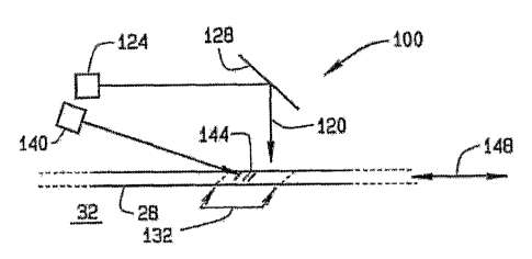
One implementation of a method of inspecting material laid by a material
placement machine, e.g., the machine 24, is indicated generally in Figure 2 by
reference number 100. A width of the material 28 is newly laid on the
substrate 32 by
the machine 24. Light is directed onto the material 28 in a direction 120
essentially
normal to the material to illuminate the material. Specifically and for
example, the light is
projected from a light source 124 onto a reflective surface 128 and reflected
by the
surface 128 onto the material 28 to illuminate a section 132 of the laid
material. The
method 100 also includes projecting laser energy onto the section 132 at an
angle
predetermined to reveal inconsistencies in the section 132. In the present
implementation, a laser source 140 projects the laser energy as one or more
lines 144
onto the section 132. The lines or stripes are projected, for example, across
an axis 148
of placement of the material 28. It should be noted that other implementations
are
3
CA 02615117 2008-01-10
05-0131 PCT
contemplated in which different laser patterns and/or laser projection
orientations may
be used.
The light source 124 above the material 28 may be configured to illuminate a
full
width of the material 28. The laser striping 144 can reveal gaps and/or
overlaps in the
material 28. Additionally, the striping can enhance the illumination from the
light source
124 and can help reveal such items as fuzz balls, resin balls, and backing
materials.
The present method can be implemented in various ways on various placement
machines. Additionally, and as further described below, implementations of the
present
method can be scaled to various widths of material to be inspected. For
example,
although a single light source 124 and a single laser source 140 are used in
the
implementation 100, a plurality of light sources and/or a plurality of laser
sources may
be used in other implementations.
One exemplary embodiment of a system for inspecting material laid by a
material
placement machine is indicated generally in Figures 3-7 by reference number
200. The
system 200 includes a frame 204 having brackets 208 configured for attachment
to a
placement machine, e.g., the machine 24 (shown in Figure 1). It should be
noted that
other embodiments of the system 200 could be configured in various ways in
relation to
material placement machines, dependent on width of material to be inspected
and
placement machine configuration. For purposes of describing the present
embodiment,
it shall be assumed that component 36 of the machine 24 is a compaction
roller. The
frame 204 is configured for attachment, for example, above and behind the
compaction
roller 36 such that the frame 204 overhangs newly laid material 28. A mirror
212 is
mounted in the frame 204, for example, at a 45-degree angle. The mirror 212 is
at least
partially silvered to provide one or more reflective portions.
A plurality of light sources 216 are mounted, for example, such that they
project
light essentially parallel to an axis 220 of placement of the material 28.
Light from the
light sources 216 may be projected toward the mirror 212 and reflected by the
mirror
reflective portion(s) onto the material 28 in a direction essentially normal
to the material.
A plurality of laser sources 224 mounted to the frame 204 are configured to
project laser energy directly onto the material 28 at an angle predetermined
to reveal
inconsistencies in the material. The laser sources 224 may be, for example,
LasarisTM
SNF line lasers by StockerYale, Inc. of Salem, New Hampshire.
4
CA 02615117 2008-01-10
05-0131 PCT
A plurality of cameras 230 are mounted in the frame 204 above the mirror 212.
The cameras 230 are configured to image, through one or more transparent
portions
234 of the mirror 212, a section of the material 28 illuminated by the light
and laser
sources 216 and 224. The cameras 230 may be actuated, for example, by the
processor 40, which receives images from the cameras 230 and/or memory 44. The
processor 40 may process the images to facilitate reliable detection of
inconsistencies.
The cameras 230 are, for example, Sony XC-HR50 cameras, although other
cameras could be used. The cameras 230 collectively have fields of view
sufficiently
broad to image a full width of the newly laid material. A wide range of
cameras can be
used, including commercially available cameras capable of acquiring black-and-
white
images. In one embodiment, a camera 230 is a television or other type of video
camera
having an image sensor and a lens through which light passes when the camera
is in
operation. Other types of cameras or image sensors can also be used, such as
an
infrared-sensitive camera, a visible light camera with infrared-pass
filtration, a fiber-optic
camera, a coaxial camera, charge-coupled device (CCD), or complementary metal
oxide semiconductor (CMOS) sensor.
The light and laser sources 216 and 224 are configured to illuminate the full
width
of the newly laid material 28. The illumination is reflected differently by
inconsistencies
in the material than by portions of the material that are free of
inconsistencies. Such
differences in illumination can be captured in images produced by the cameras
230.
The frame 204 may be configured to shield the light sources and cameras so as
to
optimize the quality of imaging by the cameras 230. It should be noted that
various
lighting and reflective configurations are possible. For example, a half-
mirror could be
used such that light from light sources is reflected by the mirror onto the
material, and
the cameras are directed not through, but past the mirror.
In the present configuration, the light sources 216 include high-intensity red
LEDs
which produce area light. Other or additional types of lighting, including but
not limited to
fluorescent lights, could be used. The quality and magnitude of surface
illumination of
the material 28 can be affected by ambient lighting and by reflectivity of the
material.
Accordingly, in one embodiment, one or more infrared light sources and/or
light sources
having an infrared component may be used to illuminate dark inconsistencies on
a dark
background. In other embodiments, a strobe or stroboscopic light source, a
noble gas
arc lamp (e.g., xenon arc), metal arc lamp (e.g., metal halide) and/or laser
(e.g., pulsed
5
CA 02615117 2008-01-10
05-0131 PCT
laser, solid state laser diode array and/or infrared diode laser array) could
be used.
Power levels and wavelengths for light source(s) 216 may depend at least in
part on the
speed and sensitivity of the cameras 230, speed at which the material 28 is
being laid,
delivery losses, and reflectivity of the material being inspected. For
example, in another
embodiment, wavelengths and power levels suitable for inspecting highly
reflective
materials may be employed.
In the configuration shown in Figures 3-7, two light sources 216, three laser
sources 224, and three cameras 230 are used. Each laser source 224 and camera
230
can cover, e.g., material widths of between about three and four inches.
Coverage could
be greater or smaller than the foregoing range depending, for example, on lens
type,
distance between material and cameras and/or laser sources, and other factors.
Depending, for example, on a width of material to be inspected and placement
system
configuration, different numbers of light sources, laser sources and/or
cameras could be
included to facilitate material inspection. The system 200 thus can be scaled
up or down
to accommodate different material widths.
When the machine 24 is in operation, motion of the machine may be detected by
the processor 40, for example, via a code ring on the compaction roller and
photo-
interrupter as disclosed in U. S. Patent Application No.10/726,099, attached
as
Appendix A, entitled "Systems and Methods For Determining Inconsistency
Characteristics of a Composite Structure."The processor 40 thereby determines
that the
machine 24 is in operation. The processor 40 actuates the cameras 230 to
obtain
images at appropriate times based on movement of the machine 24. Specifically
and for
example, by tracking distances moved by the machine 24, the processor 40 may
actuate the cameras 230 to obtain images of material newly placed on the
substrate 32
and which is currently being illuminated by the light and laser sources 216
and 224. The
processor 40 may receive each image and may assign unique numbers to frames of
the
image data from the cameras 230. The processor 40 may store image frames in
the
memory 44 and may use them to track a linear position of the machine 24 as
material is
placed on the substrate 32.
The processor 40 processes the image data in a frame to detect inconsistencies
in the imaged section of material 28. The processor 40 also analyzes and
displays
selected inconsistencies on the user interface 50. An inconsistency dimension,
for
example, an inconsistency width, can be determined as follows. After a digital
image of
6
CA 02615117 2008-01-10
05-0131 PCT
an inconsistency has been acquired, a pixel set is selected from the digital
image that
represents the width of the inconsistency. The pixels in the pixel set are
counted, and
the count is correlated with distance to determine the inconsistency width.
The processor 40 may receive images from the cameras 230 and/or memory 44
and may process the images to facilitate the reliable detection of
inconsistencies. The
processor 40 may display information on the user interface display screen 54,
for
example, as shown in Figure 8. A window 300 includes a frame 304 showing at
least
part of a section 308 of material 28 imaged by the cameras 230. For example,
an
illuminated area 312 of the section 308 is shown in the window 300. Laser
lines 320
produced by the laser sources 224 also are visible above the area 312.
Inconsistencies
324 may be labeled and are shown in the window 300. A foreign object/debris
(FOD)
330 struck by the laser lines 320 may be accentuated by the processor 40 for
display in
the frame 300. The laser striping 320 can provide a "second-look" enhancement
of
areas lighted by the light sources 216 and thus can assist in revealing
inconsistencies
such as fuzz balls, resin balls, and backing materials. It should be noted,
however, that
although the laser striping 320 strikes the material 28 above the illuminated
area 312 in
the frame 300, other arrangements of light source and laser source
illumination are
possible. In some embodiments, illumination from the light and laser sources
216 and
224 could be configured to overlap to a greater degree, or alternatively to
strike material
farther apart, than as shown in Figure 8.
It should be understood that in various implementations, images from the
cameras 230 could be displayed in various ways on the user interface 50. For
example,
images from two or more cameras 230 could be displayed simultaneously, e.g.,
side by
side in a frame on the screen 54, or sequentially in different frames.
The frame 300 may include a processed or unprocessed camera image.
Additionally or alternatively, the frame may include an image that has been
binarized.
During binarization, all shades of gray above a predetermined threshold value
can be
changed to white, while all gray shades below the threshold are changed to
black to
heighten the contrast of inconsistencies and improve the accuracy of
inconsistency
detection. In other embodiments, the binarization operation need not be
performed but
instead the raw image, rates of change of the light levels in the raw image,
and/or color
changes in the images can be used to identify the inconsistencies.
7
CA 02615117 2008-01-10
05-0131 PCT
The foregoing systems and methods provide improved illumination and
inspection across varying material widths. Various implementations of the
disclosure
provide the ability to inspect wider bands of material more effectively than
possible with
current inspection systems, which use low-incident-angle side lighting to
illuminate
material under inspection. The dual on-axis lighting provided by
implementations of the
disclosure can provide even illumination across material widths and is
scalable to
varying widths.
While various preferred embodiments have been described, those
skilled in the art will recognize modifications or variations which might be
made without
departing from the inventive concept. The examples illustrate the disclosure
and are
not intended to limit it. Therefore, the description and claims should be
interpreted
liberally with only such limitation as is necessary in view of the pertinent
prior art.
8