Note: Descriptions are shown in the official language in which they were submitted.
CA 02615289 2007-12-19
SUPPORT FOR THE STEEL PLATE CONVEYOR OF A MOBILE CRUSHER
FIELD OF THE INVENTION
[0001] The present invention pertains to the support of the steel plate
conveyor module
for a mobile crusher, which said module comprises essentially a receiving
boom, a steel plate
conveyor and a receiving hopper.
BACKGROUND OF THE INVENTION
[0002] According to the book Baumaschinen; Erdbau- und Tagebaumaschinen
[Construction Equipment, Earth-moving Machinery and Strip Mining Machinery], 1
st edition,
2002, p. 358, Section 6.3, "crusher units," mobile crushers are used in strip
mining, where the
material picked up from large dredging shovels, wheel loaders or the like
shall be loaded onto a
conveyor belt continuously in a crushed state suitable for conveying on belts.
This concept
completely avoids transportation with trucks, which causes high operating
costs. Large mobile
crushers with service weights exceeding 1,000 tons are usually moved by means
of
1
CA 02615289 2007-12-19
caterpillar-type (crawler - endless belt drive) chassis, comprising 2 to 6
caterpillars. The steel
plate conveyor module with the receiving hopper for the contents of two to
three shovels is
additionally supported in operation on the ground in order not to introduce
the heavy hopper
loads and the impact impulse into the supporting structure of the device.
[0003] The steel plate conveyor module may be supported by a lowerable support
under
the steel plate conveyor module. Such a solution is known from patent
specification DE 28 34
987 C2, where the impact force is introduced in an unfavorable manner into the
superstructure via
a hydraulic cylinder and onto the soil from the superstructure via an
adjustable support. What is
important in this solution is essentially to arrange the receiving boom with
the receiving hopper in
a height-adjustable manner, so that the loading area of the mobile crusher can
be adjusted in
height to a dredging shovel acting as a loading device, which stands on
different planes in height.
The adjusting cylinder assumes a horizontal position in the lower position of
the receiving boom
with the receiving hopper, and this horizontal position passes increasingly
over into an oblique
position during the upward adjustment. This solution is associated with the
drawback that the
supporting structure still has to absorb part of the impact impulse, which has
an unfavorable effect
in terms of fatigue strength and may lead to cracks in the superstructure.
[0004] Furthermore, a mobile crusher unit is known from the document DE 36 08
789
C2, in which the receiving boom with the receiving hopper is provided with
skids at the bottom
and is thus supported directly on the subsoil in the working position. The
forces generated by the
impact of the chunks of rock on the charging means are thus absorbed in case
of a hard and rocky
2
CA 02615289 2007-12-19
subsoil, but the vibrations generated in the process are not canceled and must
be absorbed at first
by the steel construction of the crushing plant. When the lower surface of the
support cannot be
adapted to the subsoil, the impact forces of the material are transmitted
unilaterally as wobbles to
the supporting structure of the crusher unit and thus lead to a shortening of
the service life of the
supporting framework.
[0005] The support of the steel plate conveyor of a mobile crusher embodied by
MMD
DESIGN AND CONSULTANCY LIMITED, which crusher is described and shown under the
heading "Stripping at Goonyella["] in the journal MINING MAGAZINE, January
2003 issue,
pages 15 and 16, represents an improvement. The entire steel plate conveyor
module is
articulated in this embodiment to the supporting structure approximately in
the nuddle of the
device via axles and is carried during displacement completely by two pulling
cylinders, which are
connected to jibs of the swiveling leaf form [sic - "blattform" in German
original is a probable
typo for "plattform" meaning "platform" - Tr.Ed.]. Following displacement, the
steel plate
conveyor module is partially deposited onto a one-point support under the
receiving hopper. To
maintain the balance of the device, the force of the cylinder is, however,
maintained at a constant
value at approx. 80% of the lifting force during displacement. All additional
forces from the
material contained in the hopper and the impact impulse are supported directly
under the hopper.
The MMD solution comprises an additional boom supporting structure with two-
point support in
the middle of the device and one-point support under the receiving hopper. The
lateral forces of
the steel plate conveyor module are absorbed by sliding elements into the
lateral brackets, with
which the cylinders are also coupled. Drawbacks, which result from an
eccentric impact impulse,
3
CA 02615289 2007-12-19
can be recognized in practice in this type of support. Namely, this eccentric
impact impulse
causes shock-like lateral forces, which are fully introduced at the top into
the supporting structure
and lead to damage (cracks) in the steel structure.
SUMMARY OF THE INVENTION
100061 The basic object of the present invention is to provide a support for
the charging
means of a mobile crusher unit, which charging means comprises a receiving
belt and a charging
hopper, which can automatically adapt itself to an uneven subsoil, which can
directly introduce the
forces generated from the transfer of the material directly into the subsoil
over the shortest path,
which also absorbs lateral forces and with which the shocks generated during
the itnpact of the
chunks of material can be absorbed.
[0007] This object is accomplished by arranging under the receiving hopper a
rocker
pendulum, which acts like a one-point support after being deposited after the
displacement, but
which acts as a two-point support during operation by means of two hydraulic
cylinders, which
are blocked, and also directly introduces the lateral impulses downward into
the soil. The
connections between the two hydraulic cylinders are necessary to make it
possible for the rocker
pendulum to be able to automatically adapt itself to possible unevennesses of
the soil. If a throttle
is integrated in the connection lines, the receiving hopper is not so rigid
during the impact of the
material from the dredging shovel but can yield somewhat.
[0008] The various features of novelty which characterize the invention are
pointed out
4
CA 02615289 2007-12-19
with particularity in the claims annexed to and forming a part of this
disclosure. For a better
understanding of the invention, its operating advantages and specific objects
attained by its uses,
reference is made to the accompanying drawings and descriptive matter in which
the preferred
embodiment of the invention is illustrated.
BRIEF DESCRIPTION OF THE DRAWINGS
[0009] In the drawings:
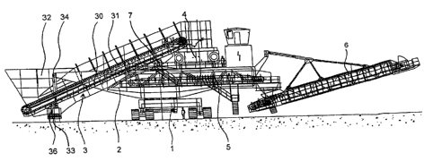
[0010] Figure 1 is a side view of a mobile crusher according to the invention;
[0011] Figure 2 is a view showing the suspension of the steel plate conveyor
module at
the superstructure of the crusher; and
[0012] Figure 3 is a view showing the lower support of the receiving-side end
of the steel
plate conveyor module.
DESCRIPTION OF THE PREFERRED EMBODIMENT
[0013] Referring to the drawings in particular the mobile crusher comprises,
according to
Figure 1, essentially the substructure 1 with the caterpillar-type chassis,
the superstructure 2, the
steel plate conveyor module 3, the crusher 4, the intermediate belt 5 and the
stacker belt 6. The
boom 30, the steel plate conveyor 31, the receiving hopper 32, and the rocker
pendulum 33
5
CA 02615289 2007-12-19
belong to the steel plate conveyor module 3. The boom 30 is articulated at the
top to the
superstructure 2 in a horizontal swivel axle 7. According to Figure 2, the
boom is adjustable in
height by means of the two hydraulic cylinders 34, 35 subjected to tensile
stress. The boom 30 is
connected at the bottom to the rocker pendulum 33 via the joint 8. The axis of
the joint 8 is
directed such that the rocker pendulum 33 can adapt itself to the unevennesses
of the subsoil 9.
[0014] The material is picked up from the dredging shovel and loaded into the
receiving
hopper 32. It is fed from there by the steel plate conveyor 31 into the
crusher 4, crushed there
and sent onto the intermediate belt 5 located under it. The material is
released from this
intermediate belt 5 via the pivotable stacker belt 6 onto a downstream face
conveyor.
[0015] After the dredging shovel has advanced by a certain stripping section,
it is brought
into the next position. The mobile crusher must perform this backward motion
to enable the
material to be emptied into the receiving hopper 32 over the short path from
the dredging shovel.
The steel plate conveyor module 3 is raised for this during the return motion
by actuating the two
hydraulic cylinders 34, 35. After the new position has been reached, the steel
plate conveyor
module 3 is lowered again until the rocker pendulum 33 lies completely on the
subsoil 9. It can
automatically compensate possible transverse slopes of the subsoil 9 due to
its articulated
mounting.
[0016] A shock-like load is generated during the impact of the material from
the dredging
shovel on the steel plate conveyor module 3. In order not to introduce this
[load] into the
6
CA 02615289 2007-12-19
superstructure 2 via the boom 30 and the two bolts thereof, which are arranged
in the swivel axle
7, the lower support by the rocker pendulum 33 is designed according to Figure
3 as a laterally
stable support. This is achieved by arranging a hydraulic cylinder 36, 37 each
on both sides of the
rocker pendulum 33. The two hydraulic cylinders 36, 37 are connected to one
another
hydraulically, so that closed hydraulic circuits are formed and the rocker
pendulum 33 can adapt
itself to the existing lateral unevennesses of the subsoil 9 during putting
down. The shock-like
lateral forces occurring during the impact of the material are thus introduced
from the receiving
hopper 32 into the subsoil 9 via the hydraulic cylinders 36, 37 and the rocker
pendulum 33. To
obtain a certain characteristic of the absorption properties, throttles 12, 13
may be integrated in
the hydraulic lines 10, 11 connecting the hydraulic cylinders 36, 37.
[0017] While specific embodiments of the invention have been shown and
described in
detail to illustrate the application of the principles of the invention, it
will be understood that the
invention may be embodied otherwise without departing from such principles.
7