Note: Descriptions are shown in the official language in which they were submitted.
CA 02615312 2013-10-30
, .
Removable Card Bridge for a Storage Card or Memory Card
BACKGROUND OF THE INVENTION
Field of the invention
This invention relates to improvements to a storage card (memory card) reader
system, and
more particularly relates to a readily replaceable memory card bridge for
protecting the receiver
of the reader from damage.
Background
Storage cards (sometimes referred to as memory cards) are increasingly popular
as an
electronic storage medium in various devices. They are used both to store data
and also to
transfer the data to other devices. These storage cards may be read and
written to by card
readers having receivers or connectors that are configured to be compatible
with a specific type
of storage card. Card readers can be contained within digital cameras, desktop
computers,
notebook computers, video cameras, televisions, and various audio and video
players; virtually
any modern electronic devices which utilizes a removable storage system for
storing data for
which a compact size is advantageous.
Currently there are many types of storage cards available on the market such
as a PCMCIA
Card, Compact Flash Card (CF card), Smart Media Card (SM Card), Memory Stick
(MS card),
Memory Stick Duo (MS Duo Card), Memory Stick Micro, Multimedia Card (MMC),
Reduced-Size
Multimedia Card (RS-MMC), Multimedia Micro Card (MMC micro), Secure Digital
Card (SD
card), mini Secure Digital Card (mini SD card), micro Secure Digital Card
(micro SD card), xD-
Picture Card (xD card) and so on. Further types of storage cards may be
developed in the
future.
4577758
CA 02615312 2013-10-30
2
As a consequence many different kinds of card readers are required, each
configured to read a
specific type or types of storage card as most of these storage cards are
incompatible with each
other having receivers (or input ports) for receiving a storage card of one
type, or perhaps
several types, of storage cards. These card readers may be internal and
external and either
accept only one type of storage card or several types of storage cards. As
these card readers
are sensitive electronic devices they are prone to damage or inoperability due
to excessive or
careless use by users. This is particularly so considering that these card
readers are often used
with portable devices due to the small size of the storage cards. Those
portable devices are
often more prone to be handled roughly, dropped or otherwise damaged through
use.
As there are many types of storage cards, when a user moves data from one
device to another
device using a storage card, the user may become confused. Furthermore users
can have
difficulty in locating a correct card reader compatible with the type of
storage card containing the
data to be transferred. In order to overcome this problem many card readers
include several
individual card readers as a multiple system in order to accept and read (or
write to) different
types of storage cards using that card reader.
In many cases an individual user will prefer one or perhaps two types of
storage cards for that
individual's storage needs. That user will make use of only one or two slots
and corresponding
connectors (sometimes called receivers) in a multiple card reader system. The
other slots and
connectors of that user's card reader will remain unused or little used. As a
consequence only
one or two connectors of the card reader will become worn out, damaged or
unusable through
repeated use or misuse, leaving the other connectors of the system undamaged
and usable.
The user is forced to either replace the card reader in its entirety, which is
unnecessarily
expensive given the number of usable components that must be discarded, or if
he is technically
astute, remove and replace only the damaged or inoperable connector of the
card reader, a
process requiring considerable skill and time. Either method is
unsatisfactory. If the damaged
or inoperable connector could be easily and cheaply replaced with a new
connector by an
unskilled individual, significant time and expense could be saved.
4577758
CA 02615312 2013-10-30
3
In another situation, in the event of failure of the card reader embedded in
an expensive
electronic device, such as a digital camera, the entire camera must usually be
replaced as the
cost of repair can often approach or exceed the cost of replacement. If the
receiver (connector)
of the card reader of digital camera could be easily and cheaply replaced with
a new connector,
then a user would not need to waste money by purchasing a new digital camera
or undertaking
expensive repairs.
These types of card readers are also embedded in many types of self-standing
user activated
commercial stations such as kiosks and the like. This can include photo
kiosks, banking kiosks,
payment kiosks and so on. Generally the kiosk itself is expensive as it
contains many complex
and expensive electronic components to provide relevant services or products
to a user. They
are not easily removed for repair or maintenance and when they are removed the
service or
products are unavailable to the user. This adversely impacts the commercial
enterprise that is
using the kiosk to service its customers, both in foregoing income from the
kiosk and in
customer dissatisfaction when attending the premises of the commercial
enterprise only to find
that the kiosk has been removed for repair or is inoperable. A damaged or
inoperable receiver
(connector) of a card reader in a kiosk can result in the inoperability of the
kiosk, or at least
inoperability by users with storage cards compatible with the inoperable
connector. If the
defective receiver (connector) of the card reader of a kiosk could be easily
and cheaply replaced
with a new receiver (connector), these problems could be overcome.
In all of these situations the replacement of the damaged receiver (connector)
of the card reader
is a difficult, expensive and time consuming task which must be undertaken by
trained
individuals.
SUMMARY OF THE INVENTION
Applicant has developed a card bridge and card reader system and method which
may be
employed to address these serious problems.
In an aspect of the invention a card bridge is provided which can be
interposed between a
connector (sometimes called a socket or receiver) of a card reader and the
storage media, such
4577758
CA 02615312 2013-10-30
4
as a storage or memory card compatible with that reader and connector. One end
of the card
bridge is configured to fit within the connector of a particular card reader
to be inserted into the
connector and the other end of the card bridge is configured with an input
slot to accept and
read and write to the storage or memory card that is compatible with the
particular card reader
and connector. The card bridge is readily removable from the reader, by simply
removing it
from the connector, such that it is replaceable by another similar bridge when
the existing bridge
is damaged or is otherwise unusable. The existing connector and other card
reader
components remain unaffected by this change. Information on the storage or
memory card in
the input slot of the bridge is then read by the card reader, and information
from the card reader
is sent to the storage or memory card for storage, through the card bridge.
In another aspect of the invention the card bridge may be configured at one
end to fit within the
connector of a particular type of card reader and have an input slot
configured to accept and
read a storage or memory card at the other end. The storage card has a
different configuration
from the storage or memory card configuration normally compatible with that
card reader. Such
a bridge would further be configured to convert data read from the storage or
memory card in
the input slot of the bridge into a form readable by the connector of the card
reader into which
the card bridge is inserted. The card bridge would be easily removable and
replaceable in the
event that the original card bridge was damaged or was otherwise inoperable.
In another aspect of the invention a card reader system is provided which
includes a plurality of
connectors configured to read different types of storage or memory cards. A
plurality of different
card bridges are configured so that a specific bridge fits within a
corresponding specific
connector such that a card bridge is inserted into each connector of the
plurality in the card
reader. The other end of each bridge is configured to accept a storage or
memory card
compatible with the connector to which it is attached. Each card bridge is
separately readily
removable and replaceable by a like card bridge in the event of damage or
inoperability of a
particular bridge of the plurality of connectors in the card reader, without
affecting the other card
bridges and without affecting any of the connectors of the card reader.
Advantageously the card reader can include a suitably dimensioned housing for
protection and
security. The housing is large enough to hold the card bridges when connected
in the
4577758
CA 02615312 2013-10-30
connectors of the card reader. The connectors are aligned with slots in the
housing to receive
the storage or memory cards such that the storage or memory cards can be
inserted into the
input slot (the card receiving section) of the card bridge or bridges through
the housing slots.
When a card bridge is damaged or is otherwise inoperable it is a simple matter
to temporarily
5 remove the housing and remove and replace the damaged or inoperable card
bridge without
having to remove or otherwise disturb the connector attached to the damaged or
inoperable
card bridge and without disturbing the other card bridges and connectors of
the card reader.
As an alternative an existing card reader may be retrofitted with the bridge
by inserting a bridge
compatible with a particular connector of a card reader into the housing slot
of that connector
and then into the connector itself. Most of the bridge is thereby positioned
externally to the
housing, being outside of the housing slot. A storage card compatible with
that bridge and
connector may be inserted into the input slot (card receiving section) of the
bridge to connect,
through the bridge, to the connector. This prevents direct connection of the
storage card with
the connector thereby saving the connector from damage. The bridge remains in
the connector
until it is necessary or desirable to replace it.
The memory card bridge may be configured in a manner which provides a
protective case for an
existing memory card. However, this "case" will include a connection between
the card bridge
and the connector on the card reader. The case will hold the storage card such
that only the
bridge will touch the storage card. The connector on the card reader will not
touch the storage
card which means that the storage card cannot damage the connector when being
inserted or in
its operation in the card reader. In the event that the storage card damages
the input slot (card
receiving section) of the bridge or its connections to the storage card, one
must only replace the
bridge; the connector is undamaged. This replacement can be undertaken at much
lower cost
as compared to replacing a damaged connector or of replacing the entire card
reader.
Advantages
By using a removable storage card (Memory Card) Bridge in a card reader, there
would be
several advantages, including:
4577758
CA 02615312 2013-10-30
6
1. Repairing or maintaining the card reader in a card reader system could
be easier,
simpler and undertaken at a minimum cost. Instead of having to replace the
entire system due
to one connector being faulty, only the bridge need be replaced. Further
instead of removing
and replacing a connector, which generally requires removal of the faulty
connector wiring from
the wiring of the card reader and then replacing the connector by reattaching
the wiring, a
bridge slips easily into the existing connector and can be easily removed by
removing the bridge
from that connector.
2. The reliability and life expectancy of the card reader would be greatly
improved. By
having to replace a relatively inexpensive bridge, rather than a damaged
connector the change
to a new working bridge can be undertaken quickly by an untrained operator at
a lower
component cost.
3. There is less opportunity for data in the storage card (memory card) to
be destroyed.
Often a storage card will become unreadable if the owner attempts to force the
card into a
connector that is incompatible with the card, damaging the card as well as the
connector. The
storage card may also become stuck within the connector if incompatible with
it. In many cases
the card bridge can be removed from the connector without removing the storage
card from the
bridge. The bridge can then more safely be removed from the storage card as
compared to
attempting to remove a stuck storage card directly from a connector. This
permits damaging the
inexpensive and easily replaceable card bridge, if necessary, in order to
salvage the storage
card, rather than having to destroy the storage card in order to save the
connector, and rather
than destroying the data in the storage card in an attempt to save the
connector and the card
reader.
4. By replacing a working card bridge from the card reader from time to
time based on a
pre-determined replacement maintenance schedule, rather than after a problem
has occurred, a
more reliable card reader will result, less likely to cause difficulties in
use. Repeated use of a
card reader can damage the sensitive internal components, usually the
connector, over time
caused by repeated use. Such a maintenance schedule ensures that the
replacement of the
bridge will reduce the opportunity for a breakdown of the card reader.
4577758
CA 02615312 2013-10-30
7
In general, the card bridges and card reader system provides a system and
method which
reduces the frequency of replacing card readers or their component parts,
improves the
reliability of system operations and permits easy replacement of the component
most
susceptible to damage or inability to operate (the card bridge). Rather than
the connector of the
card reader being damaged or rendered inoperable through use or misuse,
applicant's card
bridge will suffer the damage or will be rendered inoperable through use
instead of the
connector of the card reader. The card bridge is easily and cheaply
replaceable by untrained
individuals immediately and on-site. The connectors and the entire card reader
remains in its
working condition for substantially uninterrupted use.
The entire bridge could be inside the housing of the card reader and a user
would likely not
notice that the storage card is connected to the bridge, rather than a direct
connection to the
connector. However, in some cases (including where one must retrofit the
bridge in an existing
card reader where there is no room for the bridge between the connector and
the housing slot)
some portion of the bridge could be outside of the card reader if it
necessary.
In most cases the bridge will be used in a card reader with a properly
dimensioned housing with
sufficient room to accommodate the bridge in the corresponding connector, with
the other end of
the bridge having an input slot (card receiving section) adjacent the slot of
the housing to
receive the storage card. Alternatively, the connector can be positioned
further away from the
front bezel plate (the face plate or plate member) which contains the housing
slot, a sufficient
distance to permit the bridge to fit into the connector at one end and align
with and be
positioned adjacent the housing slot of the bezel plate. As well there would
generally be a
greater distance between connectors than before to accommodate the width of
adjacent bridges
in adjacent connectors of a multi-connector card reader.
The storage card connectors of the card reader are the same as the connectors
of a regular
card reader without the card bridge. No special connectors are required.
For the above examples, the user's storage card does not touch the connectors
on the card
reader due to the imposition of the bridge. Only the bridge will be connected
to the
4577758
CA 02615312 2013-10-30
8
corresponding connector on the card reader and only the bridge will receive
and hold the
storage card.
In this manner if there is a defective bridge due to a user mishandling a
storage card in the input
slot of the bridge, or due to mishandling, incorrect usage of storage cards or
abrasions of the
connector of the input slot (card receiving section) of the bridge, only the
bridge will need to be
replaced, which is easier, quicker and at lower cost than a replacement of a
connector of the
card reader or the replacement of the card reader itself. Similarly it will
not be necessary to
remove and replace the entire kiosk.
This bridge will assist the kiosk manufacturers, kiosk installers, kiosk
users, card reader
manufacturers, card reader installers, as well as card reader users. This type
of bridge can be
used for any type of electronic device which includes a card reader, such as
digital camera,
computers, cell phone, video camera, printer, scanner, pda, handheld computer,
mp3 player,
game machine and so on.
There exist in the art converters or adaptors for storage cards to convert one
type of smaller
storage card (like micro SD card) to larger type of storage card (SD card) to
improve the
compatibility. This assists users to use one card reader to read different
storage cards.
However, such a converter is inserted and removed from the connector of the
device repeatedly
each time it is used. It is not designed to be left inserted into the
connector such that the
storage card is repeatedly inserted and removed only into the converter, in
the manner of
applicant's bridge. These types of converters will damage the connector of
these devices in the
same manner as a storage cards, due to this repeated inserting and removal
from the
connector. They are also generally designed to adapt one type of storage card
for user in a
connector or receiver for a different type of storage card.
DESCRIPTION OF THE DRAWINGS
Figure 1 is a front perspective view depicting a memory card reader having
multiple receivers
each configured to read and write to a specific type of memory card. The
specific type of
memory card for each such receiver is shown inserted into the corresponding
receiver.
4577758
CA 02615312 2013-10-30
9
Figure 2; is a rear exploded view of a memory card reader having multiple
receivers each
configured to read and write to a specific type of memory card. The specific
type of memory
card for each such receiver is shown separately, aligned with the
corresponding receiver.
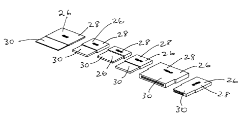
Figure 3 depicts several types of card bridges configured for use with
corresponding separate
types of memory cards and associated receivers.
Figure 4 is an exploded view of a memory card reader having multiple receivers
with
corresponding multiple memory card bridges oriented behind a plate or member
bezel.
Figure 5 depicts the internal structure of a type of memory card bridge
suitable for use with an
SD (Scan Digital) type of memory card and a receiver for operatively receiving
a SD type of
memory card.
Figure 6 depicts the SD memory card bridge of Figure 5 with an SD memory card
inserted in the
card receiving section of the bridge.
Figure 7 depicts a side sectional view of an SD memory card, an SD memory card
bridge and
SD memory card receiver of the card reader all connected together for use.
Figure 8 depicts an exemplary manner of use of the memory card bridge using an
SD memory
card about to be inserted into the card receiving section of the SD bridge.
Figure 9 depicts the exemplary manner of use of Figure 8 with the SD memory
card inserted
into the SD memory card bridge which is connected to the receiver of a card
reader.
4577758
CA 02615312 2013-10-30
DETAILED DESCRIPTION
The presented invention generally provides an improvement to card reader
system by adding a
card bridge between a storage or memory card and the connector or receiver of
a memory card
5 reader.
The addition of a bridge will significantly improve the reliability,
reparability, and life cycle of any
electronic device which utilizes a card reader. This improvement makes the
maintenance of
these devices much cheaper and simpler to the benefit of manufacturers,
assemblers,
10 distributors, service companies and users of these devices.
Figure 1 depicts memory card reader 12 which includes various types of
individual receivers 14
with compatible storage cards 20 inserted directly into each receiver 14
through the
corresponding housing slot 16 of the bezel or plate member 18. It should be
understood that
this is one example of a card reader 12. Card reader 12 may be internal or
external, some can
read different types of storage cards 20 (as depicted in Figure 1) and some
can only read one
type of storage card 20. Card readers 12 can be embedded in various electronic
devices such
as digital cameras, computers, cell phones, video cameras, printers, scanners,
PDA's, handheld
computers, Notebook PC's, MP3 players, game machines, televisions, and so on,
whether
internally or externally. Card readers are also often included with commercial
stations
containing computing systems such as kiosks and the like.
Figure 1 depicts several types of storage cards 20 with corresponding
receivers 14 for each of
those cards 20. The types of storage cards 20 include (but are not limited to)
PCMCIA Cards,
Compact Flash Cards (CF cards), Smart Media Cards (SM Cards), Memory Sticks
(MS cards),
Memory Stick Duo (MS Duo Cards), Memory Stick Micro, Multimedia Cards (MMC),
Reduced-
Size Multimedia Cards (RS-MMC), Multimedia Micro Cards (MMC micro), Secure
Digital Cards
(SD cards), mini Secure Digital Cards (mini SD cards), micro Secure Digital
Cards (micro SD
cards), xD-Picture Cards (xD cards). Further types of storage cards 20, with
corresponding
receivers 14, may be developed in the future and this invention would be
equally applicable to
those storage cards 20 and receivers 14, through appropriate configuration of
the bridge as will
become apparent.
4577758
CA 02615312 2013-10-30
11
Figure 2 is an exploded view of memory card reader 12 of Figure 1 having
multiple receivers 14
each configured to read and write to a specific type of memory card 20. The
specific type of
memory card 20 for each such receiver 14 is shown separately, aligned with its
corresponding
receiver 14.
The basic internal structure of a typical card reader includes housing 22, a
PCB (printed circuit
board) 24 with receivers 14 operatively connected thereto. Printed circuit
board 24 contains the
necessary electronic components and circuitry to read and write to memory
cards 20 when
inserted into corresponding receivers 14. A face plate 18 (sometimes called a
plate member)
contains a plurality of slots 16 (sometimes called openings). Users may insert
a storage card 20
(sometime called a memory card, smart card and so on) through slot 16 in face
plate 18 to
connect storage card 20 with the corresponding receiver 14 on the printed
circuit board 24.
As there are many types of storage cards 20, users sometimes mishandle the
card reader 12 by
attempting to force the wrong storage card 20 into a receiver 14 not
configured to accept that
type of storage card 20. Users may also cause damage to the receiver 14 by
improperly
inserting a storage card 20 into a receiver 14 which is properly configured
for that type of
storage card 20. Receivers 14 may also be damaged or rendered unusable through
normal
"wear and tear", that is through repeated use which eventually wears out the
components of
receiver 14, including through abrasion of the internal parts of receiver 14.
This occurs despite
the best efforts of manufacturers to minimise the occurrence of misuse and the
effects of
misuse as well as damage resulting from normal wear and tear on receiver 14.
These problems
can cause receiver 14 to malfunction rendering that receiver 14 unavailable
for use in reading
and writing to storage cards 20. In most cases the problems associated with
the misuse and
wear and tear occur at the receiver 14 which, absent the subject invention, is
in direct contact
with a storage card 20.
Often the malfunction or inability to function of receiver 14 of card reader
12 requires either the
replacement of the entire device associated with that card reader (for example
a kiosk,
computer, digital camera, etc.) or expensive repairs requiring the expertise
of a specialized
4577758
CA 02615312 2013-10-30
12
technician to remove the inoperable or malfunctioning receiver 14 and
replacing it with a new
receiver 14. This is an expensive and time consuming process.
The card bridge of Applicant's invention, described below, is interposed
between the storage
card 20 and receiver 14 and is replaceable cheaply and easily by a person with
little technical
expertise. By replacing a defective bridge of applicant's invention, rather
than receiver 14, that
replacement can be undertaken at significantly reduced cost, both in component
costs and the
time cost of an experienced technician. This can be undertaken on-site without
removal of the
device to a repair centre and with minimal disruption to the use of the
device.
Figure 3 depicts several types of memory card bridges 26 of the subject
invention, configured
for different types of storage cards 20 and associated receivers 14 (Figures 1
and 2). The
shape, size and type could be modified depend on the configuration of a
particular storage card
and its associated receiver 14.
Each bridge 26 includes a storage card receiving section 28 for operatively
receiving a memory
card 20 of the type associated with that particular bridge 26. Each bridge 26
further includes a
receiver insertion section 30 for operatively inserting into a receiver 14 of
the type associated
with that particular bridge 26.
Figure 4 depicts one manner of implementing the bridge system. Figure 4 is
similar to Figure 2,
but shows the bridges 26 of the subject invention interposed between receivers
14 and storage
cards 20. A plurality of bridges 26 are positioned between a plurality of
receivers 14 and
storage cards 20. Receiver insertion section 30 of each bridge 26 slips into a
corresponding
opening 34 (figure 7) (sometimes called a socket) in receiver 14 configured
for that type of
storage card 20 and is positioned in the card reader housing 22 behind face
plate18 aligned
with corresponding slot 16. A space exists between receiver 14 and face plate
18 dimensioned
with respect to bridges 26 so that bridges 26 are positioned behind the face
plate 18 when
reader 12 is assembled. Card receiving sections 28 of bridges 26 include an
opening 32
dimensioned to accept a storage card 20 of the same type as the type of
receiver 14 into which
the particular bridge 26 is inserted. In this embodiment the existence of
bridges 26 interposed
between receivers 14 and face plate 18 will not be readily apparent to a user,
nor would bridges
4577758
CA 02615312 2013-10-30
13
26 be removable by users without the removal of face plate 18, minimising the
opportunity for
bridges 26 to be removed in an unauthorised manner thereby defeating their
purpose.
However, the invention is not limited to such an internal bridge 26. Bridge 26
could be located
wholly or partially on the opposite side of face plate 18 from receiver 14,
particularly in
applications where unauthorised removal of bridge 26 is not a problem and as
well in
applications involving the retrofitting of bridges 26 for use in an existing
reader12. In that
situation a substantial part of bridge 26 would be exposed outside of the card
reader 12 face
plate 18 extending from slot 14.
Figure 5 depicts the internal structure of bridge 26. In this example bridge
26 is configured for
use with an SD type memory card and corresponding SD type receiver 14. The
receiver
insertion section 30 is positioned at one end of bridge 26 and includes the
number, position and
size of individual internal receiver insertion connectors 36 as is found at
the connection end 38
(Figure 9) of an SD type memory card in order to slip into and connect with
the opening 34
(Figure 7)(sometimes called the socket) of receiver 14 configured for an SD
memory card. The
card receiving section 28 is positioned at the opposite side of bridge 26 from
receiver insertion
section 30. Card receiving section 28 includes opening 32 which includes a
plurality of card
receiving connectors 40. Connectors 40 are the same in number, position and
size as the
individual connectors in a receiver 14 configured for an SD memory card to
enable the SD
memory card to slip into opening 32 to connect to card receiving connectors
40. Each electrical
contact connection member of connectors 40 is connected to a corresponding
respective
individual electrical contact connection member of connectors 36 through a
central region of
bridge 26 to permit data to pass through bridge 26 between the receiver 14 and
the SD memory
card 20. For example individual electrical contact connection member 42 of
connectors 36 is
directly connected to individual electrical contact connection members 44 of
connectors 40.
Figure 6 depicts an SD memory card 20 inserted into opening 32 of bridge 26
configured for an
SD memory card. Bridge 26 will hold the SD card 20 in operative electrical
connection with
connectors 40. Receiver insertion section 30 is connectable to receiver 14 of
card reader 12
configured for an SD memory card. Connectors 36 will then be in electrical
connection with
4577758
CA 02615312 2013-10-30
. .
14
internal connectors (not shown) inside opening 34 of receiver 14 configured
for an SD memory
card.
Figures 5 and 6 also depict a further advantage of this invention in showing
how opening 32 of
card receiving section 28 of the bridge 26 includes a rectangular extension 46
as a part of
opening 32 that acts as a guide to assist in the proper alignment of the SD
memory card 20 into
opening 32 for proper connection with the individual electrical contact
connection members 44
of connectors 40 the bridge 26. In this embodiment, at least 50% of the length
of the SD
memory card 20 is within extension 46. This feature reduces the risk of damage
to the SD card
20 or the card receiving section 28 and related internal connectors 40 of
bridge 26 thereby
lengthening the useful life of bridge 26.
Figure 7 is a cross-sectional view depicting bridge 26 interposed between
memory card 20 and
receiver 14 when in use. Memory card 20 is shown inserted into opening 32 of
card receiving
section 28. The connectors (not shown) at connection end 38 of memory card 20
are in
electrical contact with connectors 40 of card receiving section 28. Connectors
36 of receiver
insertion section 30 are in electrical connection with connectors 48 of
receiver 14. In this
example all three of memory card 20, bridge 26 and receiver 14 are configured
for an SD
memory card 20.
It can also be seen that memory card 20 is housed within opening 32 with a
substantial amount
of memory card 20 inside opening 32 as defined by extension 46. In this
embodiment, the
substantial amount is more than 50% of its length. This ensures that memory
card 20 enters
opening 32 and connects with connectors 40 in a parallel fashion with the
sides of opening 32 to
connect with connectors 40 in a manner which reduces the abrasion and damage
on connectors
40 as well as the connectors (not shown) of memory card 20.
Figures 8 and 9 depict bridge 26 configured for an SD memory card 20 which is
retrofitted
externally to a type of card reader 12 which as not been pre-configured for
use with bridge 26.
In this embodiment at least a portion of bridge 26 extends outside of face
plate 18 and housing
22. Bridge 26 slips into housing slot 16 configured in this example for an SD
memory card 20 to
connect internally into opening 34 of receiver 16 also configured for an SD
memory card 20. A
4577758
CA 02615312 2013-10-30
substantial part of bridge 26, including opening 32 of bridge 26 extends
outwardly from face
plate 18. SD memory card 20 can be inserted into the opening 32 to be
connected to
connectors 40 of bridge 26. Bridge 26 is, in turn, inserted into opening 34 of
receiver 14 to
provide electrical contact between connectors 36 of Bridge 26 and connectors
48 of receiver 14.
5
Figure 9 depicts SD memory card 20, bridge 26 and card reader 12 oriented in
this manner, with
bridge 26 retrofitted externally to card reader 12. Card reader 12 may then
read from and write
to SD memory card 20 through bridge 26.
10 As regards the internal bridge 26 of an embodiment of this invention,
when in use if there is
malfunction of bridge 26 for whatever reason, including to abrasion of
contacts 40 of bridge 26
or mishandling of storage card 20, the face plate 18 or the housing 22 of the
card reader 12 can
be easily removed. The inoperative bridge 26 can then be easily removed by
pulling it from
opening 34 of receiver 14 and a new bridge 26 can be inserted into opening 34
to take its place.
15 This can all be undertaken by untrained personnel simply, quickly and
cheaply. If bridge 26 is in
a card reader of a digital camera or other electronic device, and there is a
problem with that
bridge 26 through use or misuse, only bridge 26 need be replaced and the
digital camera or
other device is ready for continued use.
As regards the external bridge 26 of an embodiment of this invention preferred
for retrofitting to
an existing card reader 12, when in use bridge 26 remains in receiver
insertion section 30 of
receiver 14 and memory card or cards 20 are inserted and removed from card
receiving section
28, as desired by a user. If there is malfunction of bridge 26 for whatever
reason, including to
abrasion of contacts 40 of bridge 26 or mishandling of storage card 20, the
inoperative bridge
26 can be easily removed by pulling it from opening 34 of receiver 14 through
slot 16 and a new
bridge 26 can be inserted through slot 16 into opening 34 to take its place.
Face plate 18 is not
removed. This can all be undertaken by untrained personnel simply, quickly and
cheaply.
As will be apparent to those skilled in the art to which the invention is
addressed, the present
invention may be embodied in forms other than those specifically disclosed
above, without
departing from the essential characteristics of the invention. The particular
embodiments of the
invention described above and the particular details of the processes
described are therefore to
4577758
CA 02615312 2013-10-30
. .
16
be considered in all respects as illustrative or exemplary only and not
restrictive. Other
configurations could be developed based on known systems with card readers, or
as may in the
future be developed. The scope of the present invention is as set forth in the
complete
disclosure rather than being limited to the examples set forth in the
foregoing description.
4577758