Note: Descriptions are shown in the official language in which they were submitted.
CA 02615613 2008-01-16
WO 2007/015788 PCT/US2006/027585
[0001) METHOD AND APPARATUS FOR AUTOMATICALLY
CORRECTING RECEIVER OSCILLATOR FREQUENCY
[0002] FIELD OF INVENTION
[0003] The present invention is related to a wireless communication
system. More particularly, the present invention is related to a method and
apparatus for automatically correcting the frequency of a local oscillator
(LO)
used in a wireless receiver.
[0004] BACKGROUND
[0005] In a conventional wireless communication system including a
receiver and a transmitter, an automatic frequency correction (AFC) algorithm
is
used by the receiver for the correction of carrier frequency offset and the
sampling clock offset with respect to a transmitter. This is generally
performed
through the use of pilot signals. However, with the introduction of transmit
diversity, high speed data packet access (HSDPA) and the macro-diversity in
the
wireless communication standards, the AFC algorithm must conform to more
stringent requirements introduced by the HSDPA services.
[0006] HSDPA services employ higher con'stellation sizes to produce higher
data rates. However, higher constellations are more sensitive to frequency
errors. Therefore, HSDPA services require more robust AFC algorithm. On top of
these challenges, the AFC algorithm may operate in a macro diversity
environment where the receiver processes data from multiple cells at the same
time. For example, in a third generation partnership project (3GPP) frequency
division duplex (FDD) system, the receiver may receive data from six
neighboring
cells at the same time. In that case, there are different pilot signals from
each
cell.
[0007] The prior art does not require an AFC algorithm with HSDPA and
multiple cell processing capabilities. In general, the prior art does not deal
with
transmit diversity during AFC initial lock in period (clock synchronization
between a wireless transmit/receive unit (WTRU) and a base station). The
transmit diversity processing is performed only after the transmit diversity
-1-
CA 02615613 2008-01-16
WO 2007/015788 PCT/US2006/027585
existence is confirmed through the broadcast channel. Therefore, the transmit
diversity processing does not contribute to the AFC algorithm during the
initial
convergence period. This increases the convergence time and decreases the
probability of convergence.
[0008] The prior art has looser requirements as set by the standards for the
transmit frequency error. This is generally sufficient for a receiver with
small
constellation sizes such as binary phase shift keying (BPSK) or quadrature
phase
shift keying (QPSK). However, higher constellations at and above 16 QPSK
require more stringent requirements. For example, the 3GPP FDD standards
require less than 0.1 ppm frequency error in the AFC algorithm. The HSDPA
services are noticeably degraded after the frequency error exceeds 0.05 ppm.
This requirement forces the AFC algorithm to make efficient usage of the
transmit diversity and the macro diversity which were either ignored or
unnecessary in the prior art.
[0009] SUMMARY
[0010] The present invention is related to a method and apparatus for
automatically correcting the frequency of an oscillator in an analog radio by
generating a voltage controlled oscillator (VCO) control voltage signal. AFC
algorithm in accordance with the present invention uses a common pilot channel
(CPICH) as a reference signal to measure the frequency error in the WTRU.
[0011] A primary CPICH code sequence is generated by a CPICH code
generator based on a reference cell identification signal and a frame start
signal.
The received despread CPICH sequence is used to generate an estimated
frequency error signal. The control voltage signal is generated by a control
voltage generator based on the estimated frequency error signal. The CPICH
code generator generates the CPICH code sequence based on signals received
from an AFC reference cell. The AFC reference cell may be an HSDPA serving
cell when HSDPA service is active, or may be a timing reference cell when
HSDPA service is not active. Alternatively, a fixed reference cell can be used
for
AFC algorithm without any switching between the CPICH reference codes
-2-
CA 02615613 2008-01-16
WO 2007/015788 PCT/US2006/027585
corresponding to different cells. The present invention achieves full maximum
ratio combining (MRC) gain when space time transmit diversity (STTD) is used,
even without receiving a transmit diversity indication. This can be used by
any
Alamouti based transmit diversity scheme.
[0012] BRIEF DESCRIPTION OF THE DRAWINGS
[0013] A more detailed understanding of the invention may be had from the
following description of a preferred embodiment, given by way of example and
to
be understood in conjunction with the accompanying drawing wherein:
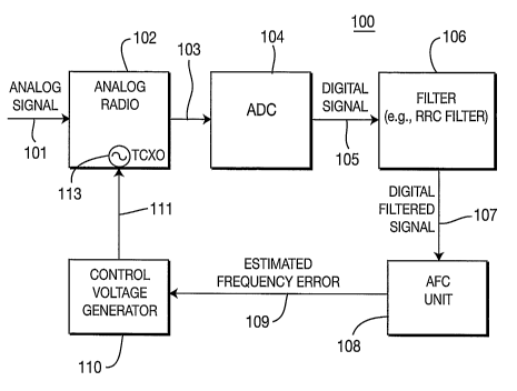
[0014] Figure 1 is a simplified block diagram of a receiver including an
AFC unit and control voltage generator in accordance with the present
invention;
[0015] Figure 2 is a block diagram of the receiver of Figure 1 which shows
details of the configuration of the AFC unit and the control voltage
generator;
[0016] Figure 3 is a block diagram of an AFC subunit of the receiver of
Figure 1; and
[0017] Figure 4 is a diagram of a loop filter in the AFC unit of the receiver
of Figure 1.
[0018] DETAILED DESCRIPTION OF THE PREFERRED EMBODIMENTS
[0019] Hereafter, the terminology "WTRU" includes but is not limited to a
user equipment, mobile station, fixed or mobile subscriber unit, pager, or any
other type of device capable of operating in a wireless environment.
[0020] The features of the present invention may be incorporated into an
integrated circuit (IC) or be configured in a circuit comprising a multitude
of
interconnecting components.
[0021] Figure 1 is a simplified block diagram of a receiver 100 including an
analog radio 102 with a voltage controlled temperature compensated crystal
oscillator (TCXO) 113, an analog-to-digital converter (ADC) 104, a filter 106,
(e.g., a root raised cosine (RRC) filter), an AFC unit 108 and a control
voltage
generator 110 which controls the frequency of the TCXO in accordance with the
present invention. A received radio frequency (RF) signal 101 through the
-3-
CA 02615613 2008-01-16
WO 2007/015788 PCT/US2006/027585
antenna (not shown) is processed by the analog radio 102 to generate a
baseband
signal by mixing the received RF signal with a signal generated using the TCXO
113. The baseband signal 103 is converted to a digital signal 105 by the .ADC
104. The digital signa1105, which is preferably 2X over-sampled signal, is
input
to the filter 106, (for pulse shaping), which outputs the filtered digital
signal 107
to the AFC unit 108. It should be noted that 2X sampling rate is an example
and
any sampling rate may be implemented. The AFC unit 108 generates an
estimated frequency error signal 109. The estimated frequency error signa1109
is converted to a TCXO control voltage signal 111 by the control voltage
generator 110.
[00221 The frequency of the TCXO 113 in the analog radio 102 is
determined based on the TCXO control voltage signal 111. The frequency of the
ideal TCXO 113, is proportional to the TCXO control voltage signal 111 as
follows:
[00231 fTcxo = 11 = Vlont . Equation (1)
where A is the slope of the TCXO control curve which is determined by the
particular TCXO being used, fTcxo is TCXO frequency and Veonx is the TCXO
control voltage.
[0024] In general, the frequency difference between LOs of the transmitter
and the receiver in a universal terrestrial radio access (UTRA) FDD system may
be as large as 3 ppm. This corresponds to a frequency error of approximately
6
kHz at carrier frequencies near 2 GHz.
[0025] In accordance with the present invention, an AFC algorithm is
based on the difference of successive phase estimates. The AFC algorithm may
be implemented in different rates depending on system requirements. For
example, the .AFC algorithm may be implemented in three different modes: fast,
slow and freeze. In the fast mode, the AFC algorithm updates the frequency
error estimate faster than the slow mode. In the freeze mode, the AFC
algorithm
keeps the last frequency error estimate until the freeze mode is over, (i.e.,
the
frequency error estimate will remain the same during freeze). The freeze mode
may be used for compressed mode and other special cases.
-4-
CA 02615613 2008-01-16
WO 2007/015788 PCT/US2006/027585
[0026] In 3GPP FDD Release 5, macro diversity is supported. Thus, a
WTRU can receive and demodulate signals from up to six different cells in the
active cell list. In accordance with the present invention, macro diversity
processing is supported in a simplified way
[0027] In the receiver 100 of Figure 1, the AFC unit 108 processes only one
cell at any given time. The cell is either an HSDPA serving cell or a timing
reference cell. However, any cell can be used by this algorithm without any
modification of the signal processing flow. The HSDPA serving cell is the cell
that transmits high speed packet data to the WTRU and the timing reference
cell
is the cell where the WTRU receives all other services such as voice
communications. These cells may be the same cell or a different cell.
[0028] If HSDPA is active, the AFC unit 108 processes only signals from
the HSDPA serving cell. This means that the frequency is synchronized to the
HSDPA serving cell. If HSDPA is not active, then the AFC unit 108 only
processes signals from the timing reference cell. The AFC reference cell,
(i.e.,
either the HSDPA serving cell or the timing reference cell), can only be
changed
just after the TCXO 113 of the analog radio 102 is updated by the TCXO control
voltage signal 111 output by the control voltage cell 110, and before the
processing for a new update begins.
[0029] Preferably, the AFC unit 108 uses a primary CPICH as a reference
channel to measure the carrier frequency error in the received signal. It
should
be noted that any type of channels transmitting a sequence known to both the
transmitter and the receiver may be utilized. The CPICH may be transmitted
with STTD on or off. Although the AFC unit 108 makes use of the transmit
diversity in the CPICH, it does not need the transmit diversity indicator.
[0030] A STTD is a practical application of Alamouti transmit diversity
method. The Alamouti transmit diversity is very popular since it has a very
simple processing in the receiver. However, this processing does not apply
when
there is a big frequency offset between adjacent symbols or when the transmit
diversity information is unknown. The AFC algorithm in accordance with the
present invention obtains full MRC gain of the STTD scheme without a trasnmit
-5-
CA 02615613 2008-01-16
WO 2007/015788 PCT/US2006/027585
diversity indicator. This is obtained through quadruple processing and
discarding the first and last symbols per frame. Quadruple processing is a
process for producing one phase error estimate from four successive CPICH
symbols.
[0031] Figure 2 is a block diagram of the receiver 100 of Figure 1 which
shows details of the configuration of the AFC unit 108 and the control voltage
generator 110. In accordance with the present invention, the AFC unit 108
includes an AFC subunit 201 which includes a CPICH code generator 202, a
sliding window correlator 204, a phase vector generator 206 and a phase vector
combiner 208. The AFC unit 108 further includes~a multi-path combiner 210, a
phase error estimator 212, an averaging unit 214 and a loop filter 216.
[0032] In the AFC unit 108, an AFC algorithm is performed continuously
after completion of the initial cell search. A reference cell identification
signal
252, (i.e., a cell ID of an HSDPA serving cell or a timing reference cell) and
a
frame start signa1254 are input to the CPICH code generator 202. The AFC unit
108 starts up after the frame start signal 254 is provided. The P-CPICH code
generator 202 generates a CPICH code sequence 203 based on a primary
scrambling code sequence of the reference cell. The CPICH code generator 202
is
reset every frame and operates at lx the chip rate. The CPICH code generator
202 creates a complex CPICH code sequence 203 corresponding to antenna 1
independent of whether the STTD is on or off.
[0033] The CPICH code sequence 203 is input to the sliding window
correlator 204. The sliding window correlator 204 computes a complex
correlation between the filtered digital signa1107 and the CPICH code sequence
203 at successive points in time.
[0034] For each CPICH symbol, a sliding window complex correlation is
preferably performed at every possible multipath location. The AFC unit 108
processes multiple successive CPICH symbols. For example, the sliding window
correlator 204, the phase vector generator 206 and the phase vector combiner
208
may be configured to process every four CPICH symbols, (a quadruple).
Hereinafter, the present invention will be explained with reference to the
case of
-6-
CA 02615613 2008-01-16
WO 2007/015788 PCT/US2006/027585
four symbols and universal mobile telecommunication services (UMTS) system as
an example. However, it should be noted that the following description,
(especially numerical description), is provided only for illustration
purposes, not
as a limitation, and the any number can be implemented, (e.g., any number of
symbols can be processed as a basis for generating a phase error signal).
[0035] In UMTS, one frame comprises 15 time slots and each time slot
comprises 2,560 chips and a CPICH symbol sequence is spread with spreading
factor of 256. Therefore, 10 CPICH symbols are transmitted in each time slot
and 150 symbols are transmitted in each frame. The symbols are preferably, but
not necessarily, taken beginning from the second symbol in each frame. The
first
and the last symbols in each frame are discarded and the remaining 148
symbols,
(which comprise 37 quadruples), are processed by the sliding window correlator
204 by quadruple by quadruple.
[0036] Figure 3 is a block diagram of the AFC subunit 201 of the AFC unit
108 of the receiver 100. As shown in Figure 3, the sliding window correlator
204
preferably includes a plurality of vector correlators 274, each assigned to a
particular position of a multipath component. Each vector correlator 274
processes the CPICH code sequence 203 generated by an associated CPICH code
generator 202.
[0037] As shown in Figure 3, the successive CPICH symbols are
represented by Sk, Sk+1, Sk+2 and Sk+3, where k is the symbol index. The
corresponding complex correlation values for these symbols are represented by
Ck( m), Ck+z( m), Ck+2(m) and Ck+a( m), respectively, where index m represents
the integer multi-path location. The complex correlations can be represented
as
follows:
(k+1)256-1
Ck (m) = jr(n) p * (n - na) ; Equation (2)
n=k*256
(k+2)256-1
Ck+l (nz) _ E r(n) p * (n - na) ; Equation (3)
n=(k+1)"256
(k+3)256-1
Ck+2 (rn) Yr(n) p * (n - nz) ; Equation (4)
n=(k+2)*256
-7-
CA 02615613 2008-01-16
WO 2007/015788 PCT/US2006/027585
(k+4)256-1
Ck+3 (jn) = Er(ra) p * (fl - 7Y2) ; Equation (5)
n=(k+3)*256
where k - 2,6,10,14...........146 1 tn =-5,. - 4........ ,0,1....... 50 r(n)
represents the despread
input sequence, p(n-m) represents the pilot sequence corresponding to time-
shift
m and n represents discrete time index. As seen from Equations (2) through
(5),
for each symbol there are 56 complex correlations performed for each of even
and
odd sequences.
[0038] The phase vector generator 206 comprises a complex conjugate unit
276 and a multiplier 278. The complex conjugate unit 276 generates complex
conjugate of vector correlation of one of the two consecutive symbols in a
quadruple, such as two symbols Sk+i and Sk+3. The multiplier 278 multiplies
the
vector correlation of Sk and complex conjugate of the vector correlation of
Sk+i to
generate a phase vector Pl and multiplies the vector correlation of Sk+2 and
complex conjugate of the vector correlation of Sk+3 to generate a phase vector
P2.
The input rate of the phase vector generator is 1/Ts and the output rate is 1
I2Ts
where T. is the CPICH symbol rate.
[0039] The phase vectors PI and P2 accounts for a phase error
corresponding to the phase difference between two symbols, (i.e., 256 chips).
The
phase vectors PI and P2 are obtained as follows:
1'k (jn) = Ck (jn)Ck+l* (jn), Equation (6)
Pk (ii2) = Ck+2 (In)Ck+3* (nz) . Equation (7)
[0040] The phase vector combiner 208 comprises an adder 280. The adder
280 adds the two phase vectors PI and P2 in each quadruple. Therefore, for
each
quadruple, one combined phase vector is generated as follows:
Pk (rn) = Pk (f72) + Pk (T72) . Equation (8)
[0041] The input rate of the phase vector combiner is 1 I2T3 and the output
rate is 1/4Ts. When transmit diversity is on, this operation corresponds to
adding in-phase and out-of-phase components from two antennas. If there is no
transmit diversity, this corresponds to adding two successive phase vectors
-8-
CA 02615613 2008-01-16
WO 2007/015788 PCT/US2006/027585
corresponding to a single antenna.
[0042] In either case the above equations result in full processing gain.
This means when there is transmit diversity it performs like an MRC and when
there is no transmit diversity there is no loss due to quadruple processing.
This
is achieved without knowing the transmit diversity indicator (whether transmit
diversity on or off).
[0043] For each quadruple, (i.e., four successive symbols), this operation,
(i.e., correlation, phase vector generation and phase vector combining), is
repeated.
[0044] Referring to Figure 2, the multipath combiner 210 combines the
combined phase vectors corresponding to different multi-path locations for
both
even and odd sequences. The purpose of the multipath combiner 210 is to
eliminate weak multipath components and combine only the strongest ones. All
the combined phase vectors are compared to a threshold in magnitude and only
the ones having a magnitude greater than the threshold are combined and others
are discarded. The threshold may be defined based on the strongest combined
phase vector. The strongest one, Pmax, among all the paths is defined as
follows:
Ipm. (k)l = mm Xl(pk (,n)I Equation (9)
where m=-5,-4,-3, 2,-1,0,1,2,.........50 . The maximum is found at a rate of
one
fourth of the symbol rate (1 /4Ts). The threshold may be defined by
multiplying a
scale factor to the maximum as follows:
m E M<* P,n I_ (afc_path_ihresh) xIPm. I. Equation (10)
[0045] The magnitude may be calculated using the following approximation
formula:
absapp,.ox {z}= max~Re{z~,IIm{z}I)+Y2 mi*e{z~,IIm{z~>. Equation (11)
[0046] The multipath combined vector, P, is simply the coherent addition of
all the phase vectors above the threshold as follows:
Pk = I P. (ln)
nleM
Equation (12)
The input and output rate of the combiner is 1/ 4Ts.
-9-
CA 02615613 2008-01-16
WO 2007/015788 PCT/US2006/027585
[0047] The phase error estimator 212 calculates the phase angle of the
combined phase vector, P. The phase angle of the phase vector is equal to
inverse
tangent of its argument. A coarse approximation may be used for the phase
error. This approximation produces accurate results only for small phase
angles.
However, that is the only time its accuracy actually matters. The phase
error, b B, is given by:
A B N Im{Ppv} Equation (13)
abS.PProx {Pav }
The input and output rate of the phase error estimator 212 is 1/4Ts.
[0048] The estimated phase error is averaged by the averaging unit 214
over multiple frames before being passed to the loop filter 216. The averaging
is
as follows: !
A = 1 Y'OB. Equation (14)
Mav Ma,
[0049] The averaging time depends on the AFC mode. For example, in the
fast mode, averaging time may be two frames corresponding to 74 quadruples,
(i.e., Mdu = 74). In the slow mode, averaging time may be twenty frames
corresponding to 740 quadruples, (i.e., MaU = 740).
[0050] After the averaging period is completed, the average phase error is
reset before the next averaging period. The input rate to the averaging unit
214
is 1/4Ts and output rate is either every two frames or every 20 frames.
[0051] The loop filter 216 is a weighted integrator as shown in Figure 4.
The output 215 from the averaging unit 214 is multiplied by a coefficient 8
282
and integrated by an adder 284 and a delay unit 286. The output of the loop
filter 216 can be written as follows:
AB = '6 = jAB. Equation (15)
The input and output rates of the loop filter 216 are same, either every two
or
twenty frames depending on the AFC mode of operation.
[0052] Referring again to Figure 2, the control voltage generator 110
includes a control voltage computation unit 218 and a digital-to-analog
converter
-10-
CA 02615613 2008-01-16
WO 2007/015788 PCT/US2006/027585
(DAC) 220. The estimated phase error signa1109 output from the loop filter 216
and an assigned receiver carrier frequency 256 are input to the control
voltage
computation unit 218. The control voltage computation unit 218 calculates a
frequency correction value. The frequency correction value 219 is simply the
phase error divided by the time duration between successive two symbols.
Therefore, the frequency correction value 219 is computed as follows:
f = Equation (16)
~ T ~
s
where Ts is the symbol duration. The frequency correction value 219 is then
converted to a digital-to-analog converter (DAC) step length, which becomes
the
TCXO control voltage sig.na1111. For example, the DAC 220 may have 12 bits
resolution and, therefore, 4096 levels. Assuming that the approximate dynamic
range of the TCXO is 8 ppm corresponding to 16 kHz or a total of 32 kHz for
2
GHz carrier frequency, the digital-to-analog converter (DAC) step size, S,
equals
to 32000 /4096 =7.81 Hz. The TCXO control voltage signal 111 is simply found
by:
E
quation (17)
VTCXO = IA- sI
where A is the slope of the TCXO control curve as shown in Equation (1). It
has
been assumed that A =1. However, A may have a value determined by the
physical TCXO 113 being used. The value A should be included in the total loop
gain. Therefore, after a practical average value for .1 is determined by the
particular TCXO 113 being used, the loop filter coefficient, ~, should be
adjusted
as follows:
Equation (18)
[0053] The TCXO control voltage signal 111 is applied to the TCXO 113 in
the analog radio 102, (for example, every two or twenty frames depending on
the
fast or slow mode of operation, respectively).
[0054] Embodiments.
[0055] 1. A method of automatically correcting the frequency of a local
oscillator of a receiver in a wireless communication system where pilot
symbols
-11-
CA 02615613 2008-01-16
WO 2007/015788 PCT/US2006/027585
are transmitted through a pilot channel.
[0056] 2. The method of embodiment 1 comprising the step of
converting a received RF signal to a baseband signal using a signal generated
by
the local oscillator, the frequency of the local oscillator being controlled
by a
control voltage signal.
[0057] 3. The method as in any embodiments 1-2, comprising the step
of generating samples of the baseband signal.
[0058] 4. The method of embodiment 3 further comprising the step of
generating a phase error signal by processing samples corresponding to a
predetermined number of consecutive pilot symbols with a corresponding pilot
code sequence.
[0059] 5. The method of embodiment 4 further comprising the step of
generating a control voltage signal based on the phase error signal.
[0060] 6. The method as in any embodiments 4-5, wherein the phase
error signal is generated by the step of generating a pilot code sequence
corresponding to N consecutive pilot symbols by N pilot code sequence
generators.
[0061] 7. The method of embodiment 6 further comprising the step of
generating a complex correlation of samples and a pilot code sequence for each
of
the N consecutive pilot symbols by N sliding window correlators.
[0062] 8. The method of embodiment 7 further comprising the step of
generating a phase vector between two consecutive pilot symbols by a plurality
of phase vector generators.
[0063] 9. The method of embodiment 8 further comprising the step of
generating a combined phase vector by combining phase vectors generated by the
plurality of phase vector generators.
[0064] 10. The method of embodiment 9 further comprising the step of
generating the phase error signal based on the combined phase vector.
[0065] 11. The method as in any embodiments 3-10 further comprising
the step of averaging the phase error signal and accumulating the averaged
phase error signal.
-12-
CA 02615613 2008-01-16
WO 2007/015788 PCT/US2006/027585
[0066] 12. The method as in any embodiments 5-11, wherein the control
voltage is generated by the steps of generating a frequency correction value
from
the phase error.
[0067] 13. The method of embodiment 12 further comprising the step of
generating the control voltage signal by converting the frequency correction
value
to a corresponding analog value with a DAC.
[0068] 14. The method as in any embodiments 1-13, wherein the pilot
code sequence is generated corresponding to an AFC reference cell.
[0069] 15. The method of embodiment 14 wherein the AFC reference cell
is a HSDPA serving cell when HSDPA service is active.
[0070] 16. The method of embodiment 14 wherein the AFC reference cell
is a timing reference cell when HSDPA service is not active.
[0071] 17. The method as in any embodiments 1-16, wherein STTD is
used in transmission of the pilot symbols.
[0072] 18. The method of embodiment 17 wherein MRC is achieved
without receiving a transmit diversity indication.
[0073] 19. The method of embodiment 17 wherein the STTD is
implemented by Alamouti transmit diversity.
[0074] 20. The method as in any embodiments 1-19, wherein the pilot
code sequence is a CPICH code sequence.
[0075] 21. The method as in any embodiments 4-20, wherein samples
corresponding to every four consecutive pilot symbols are processed to
generate
the phase error signal.
[0076] 22. A receiver configured to automatically correct frequency error
of a local oscillator in a wireless communication system where pilot symbols
are
transmitted through a pilot channel.
[0077] 23. The receiver of embodiment 22 comprising an analog radio for
converting a received RF signal to a baseband signal using a signal generated
by
the local oscillator, the frequency of the local oscillator being controlled
by a
control voltage signal.
[0078] 24. The receiver as in any embodiments 22-23 comprising an
-13-
CA 02615613 2008-01-16
WO 2007/015788 PCT/US2006/027585
AllC for generating samples ot the baseband signal.
[0079] 25. The receiver of embodiment 24 comprising an AFC unit for
generating a phase error signal by processing samples corresponding to a
predetermined number of consecutive pilot symbols with a corresponding pilot
code sequence.
[0080] 26. The receiver of embodiment 25 comprising a control voltage
generator in communication with the analog radio and the AFC unit, the control
voltage generator for generating the control voltage signal based on the phase
error signal.
[0081] 27. The receiver as in any embodiments 25-26, wherein the AFC
unit comprises N pilot code sequence generators, each pilot code sequence
generator generating a pilot code sequence corresponding to N consecutive
pilot
symbols.
[0082] 28. The receiver of embodiment 27, wherein the AFC unit
comprises N sliding window correlators, each sliding window correlator
generating a complex correlation of samples and a pilot code sequence for each
of
the N consecutive pilot symbols.
[0083] 29. The receiver of embodiment 28, wherein the AFC unit
comprises a plurality of phase vector generators, each phase vector generator
generating a phase vector between two consecutive pilot symbols.
[0084] 30. The receiver of embodiments 29, wherein the AFC unit
comprises a phase vector combiner for generating a combined phase vector by
combining phase vectors generated by the plurality of phase vector generators.
[0085] 31. The receiver of embodiment 30, wherein the AFC unit
comprises a phase error estimator for generating the phase error signal based
on
the combined phase vector.
[0086] 32. The receiver as in any embodiments 25-31, wherein the AFC
unit further comprises an averaging unit for averaging the phase error sigrial
generated by the phase error estimator.
[0087] 33. The receiver of embodiment 32, wherein the AFC unit
comprises a loop filter for accumulating the averaged phase error signal.
-14-
CA 02615613 2008-01-16
WO 2007/015788 PCT/US2006/027585
[0088] 34. The receiver as in any embodiments 25-33, wherein the AFC
unit comprises a multipath combiner and multiple sets of N pilot code sequence
generators, N sliding window correlators, phase vector generators and a phase
vector combiner, each set being assigned to one of a plurality of multipath
components, whereby the multipath combiner combines outputs of the phase
vector combiners.
[0089] 35. The receiver as in any embodiments 26-34, wherein the
control voltage generator comprises a control voltage computation unit for
generating a frequency correction value based on the phase error.
[0090] 36. The receiver of embodiment 35, wherein the control voltage
generator comprises a DAC for generating the control voltage signal based on
the
frequency correction value.
[0091] 37. The receiver as in any embodiments 27-36, wherein each of
the pilot code sequence generators generates the pilot code sequence signal
corresponding to an AFC reference cell.
[0092] 38. The receiver of embodiment 37 wherein the AFC reference
cell is a HSDPA serving cell when HSDPA service is active.
[0093] 39. The receiver of embodiment 37 wherein the AFC reference
cell is a timing reference cell when HSDPA service is not active.
[0094] 40. The receiver as in any embodiment 22-39, wherein STTD is
used in transmission of the pilot symbols.
[0095] 41. The receiver as in any embodiments 22-40, wherein MRC is
achieved without receiving a transmit diversity indication.
[0096] 42. The receiver of embodiment 41, wherein the STTD is
implemented by Alamouti transmit diversity.
[0097] 43. The receiver as in any embodiments 22-42, wherein the pilot
code sequence is a CPICH code sequence.
[0098] 44. The receiver as in any embodiments 27-43, wherein each of
the pilot code sequence generators is reset every time a frame start signal
indicates that a new frame is starting.
[0099] 45. The receiver as in any embodiments 27-44, wherein each of
-15-
CA 02615613 2008-01-16
WO 2007/015788 PCT/US2006/027585
the pilot code sequence generators operates at a chip rate.
[00100] 46. The receiver as in any embodiments 25-45, wherein samples
corresponding to every four consecutive pilot symbols are processed to
generate
the phase error signal.
[00101] 47. An IC configured to automatically correct frequency error of a
local oscillator of the receiver in a wireless communication system where
pilot
symbols are transmitted through a pilot channel.
[00102] 48. The IC of embodiment 47 comprising an analog radio for
converting a received RF signal to a baseband signal using a signal generated
by
the local oscillator, the frequency of the local oscillator being controlled
by a
control voltage signal.
[00103] 49. The IC as in any embodiments 47-48 comprising an ADC for
generating samples of the baseband signal.
[00104] 50. The receiver of embodiment 49 comprising an AFC unit for
generating a phase error signal by processing samples corresponding to a
predetermined number of consecutive pilot symbols with a corresponding pilot
code sequence.
[00105] 51. The receiver of embodiment 50 comprising a control voltage
generator in communication with the analog radio and the AFC unit, the control
voltage generator for generating the control voltage signal based on the phase
error signal.
[00106] 52. The receiver as in any embodiments 50-51, wherein the AFC
unit comprises N pilot code sequence generators, each pilot code sequence
generator generating a pilot code sequence corresponding to N consecutive
pilot
symbols.
[00107] 53. The receiver of embodiment 52, wherein the AFC unit
comprises N sliding window correlators, each sliding window correlator
generating a complex correlation of samples and a pilot code sequence for each
of
the N consecutive pilot symbols.
[00108] 54. The receiver of embodiment 53, wherein the AFC unit
comprises a plurality of phase vector generators, each phase vector generator
-16-
CA 02615613 2008-01-16
WO 2007/015788 PCT/US2006/027585
generating a phase vector between two consecutive pilot symbols.
[00109] 55. The receiver of embodiments 54, wherein the AFC unit
comprises a phase vector combiner for generating a combined phase vector by
combining phase vectors generated by the plurality of phase vector generators.
[00110] 56. The receiver of embodiment 55, wherein the AFC unit
comprises a phase error estimator for generating the phase error signal based
on
the combined phase vector.
[00111] 57. The receiver as in any embodiments 50-56, wherein the AFC
unit further comprises an averaging unit for averaging the phase error signal
generated by the phase error estimator.
[00112] 58. The receiver of embodiment 57, wherein the AFC unit
comprises a loop filter for accumulating the averaged phase error signal. '
[00113] 59. The receiver as in any embodiments 50-58, wherein the AFC
unit comprises a multipath combiner and multiple sets of N pilot code sequence
generators, N sliding window correlators, phase vector generators and a phase
vector combiner, each set being assigned to one of a plurality of multipath
components, whereby the multipath combiner combines outputs of the phase
vector combiners.
[00114] 60. The receiver as in any embodiments 51-59, wherein the
control voltage generator comprises a control voltage computation unit for
generating a frequency correction value based on the phase error.
[00115] 61. The receiver of embodiment 60, wherein the control voltage
generator comprises a DAC for generating the control voltage signal based on
the
frequency correction value.
[00116] 62. The receiver as in any embodiments 52-61, wherein each of
the pilot code sequence generators generates the pilot code sequence signal
corresponding to an AFC reference cell.
[00117] 63. The receiver of embodiment 62 wherein the AFC reference
cell is a HSDPA serving cell when HSDPA service is active.
[00118] 64. The receiver of embodiment 62 wherein the AFC reference
cell is a timing reference cell when HSDPA service is not active.
-17-
CA 02615613 2008-01-16
WO 2007/015788 PCT/US2006/027585
[00119] 65. The receiver as in any embodiment 47-64, wherein STTD is
used in transmission of the pilot symbols.
[00120] 66. The receiver as in any embodiments 47-65, wherein MRC is
achieved without receiving a transmit diversity indication.
[00121] 67. The receiver of embodiment 66, wherein the STTD is
implemented by Alamouti transmit diversity.
[00122] 68. The receiver as in any embodiments 47-67, wherein the pilot
code sequence is a CPICH code sequence.
[00123] 69. The receiver as in any embodiments 52-68, wherein each of
the pilot code sequence generators is reset every time a frame start signal
indicates that a new frame is starting.
[00124] 70. The receiver as in any embodiments 52-69, wherein each of
the pilot code sequence generators operates at a chip rate.
[00125] 71. The receiver as in any embodiments 50-70, wherein samples
corresponding to every four consecutive pilot symbols are processed to
generate
the phase error signal.
[00126] Although the features and elements of the present invention are
described in the preferred embodiments in particular combinations, each
feature
or element can be used alone without the other features and elements of the
preferred embodiments or in various combinations with or without other
features
and elements of the present invention.
~x * ~x
-18-