Note: Descriptions are shown in the official language in which they were submitted.
CA 02615772 2008-01-17
WO 2007/016310 PCT/US2006/029336
NIOBIUM OXIDE COMPOSITIONS,.NANOSTRUCTURES, BIOACTIVE
FORMS AND USES THEREOF
PRIORITY CLAIM
This Application claims the benefit of US
Provisional Patent Application No. 60/703,366 filed on
July 28, 2005, which is incorporated herein by
reference in its entirety.
TECHNICAL FIELD OF THE INVENTION
The present invention relates to the formation and
use of niobium oxides, including methods of forming
crystalline niobium oxides with defined nanostructure
morphologies features and/or with useful bioactivities.
CA 02615772 2008-01-17
WO 2007/016310 PCT/US2006/029336
2
BACKGROUND
Niobium oxides were studied initially because of
their utility in the construction of solid electrolyte
capacitors [1] and superconductivity [2]. Recently,
however, niobium oxide has commanded additional
attention due to its promising potential in medical
applications [3]. Perhaps, the most favorable form of
niobium oxide in many applications is Nb205 due to its
high resistivity to chemical attack, strong affinity to
oxygen, carbon, and nitrogen, thermodynamic stability,
and biocompatibility.
Typically, niobium oxide is formed through either
a sol-gel process or electrochemical anodization. For
further discussion please see, for example, [4,5].
Because of the great promise that niobium oxides
have in applications ranging from electrical devices to
medical implants there is a continued need for niobium
oxides with useful properties and for methods for
making niobium oxides. One aspect of the invention is
to meet these needs.
CA 02615772 2008-01-17
WO 2007/016310 PCT/US2006/029336
3
SUMMARY
One aspect is a material substantially comprising
niobium oxide and having a well defined morphology and
composition.
One embodiment is a self-organized composition
including niobium oxide that can be prepared by
potentiostatic anodization carried out in the presence
of an electrolytic solution including an inorganic acid
such as HF(aq).
Another embodiment is self-organized compositions
of metal oxides formed by anodizing virtually any
reactive metal or mixture thereof.
Still another embodiment is self-organized
compositions of metal oxides formed by anodizing at
least one metal selected from the group consisting of
Al, Ti, and Zr in the presence of an electrolyte
including, for example, dilute solutions of HF(aq).
In one embodiment the anodization is carried out
in the presence of between about 0.25 wt. percent to
about 10 wt. percent HF(aq.). In another embodiment the
concentration of HF (aq.) is about 2.5 wt. percent. In
still another embodiment HF (aq.) is supplement with
another acid, for example, phosphoric acid.
Another embodiment is a method of forming niobium
oxides that have a defined morphology and/or topology
by anodizing niobium metal and controlling anodization
parameters including electrolyte strength, voltage at
constant potential, temperature. In one embodiment the
electrolyte includes a salt that is soluble under the
anodization conditions and that interacts with niobium
CA 02615772 2008-01-17
WO 2007/016310 PCT/US2006/029336
4
metals example of suitable salts include, but are not
limited to NaF and Na2SO4.
In one embodiment the anodization reaction of
niobium metal to form niobium oxide is carried at a
temperature range from about -10 degrees Celsius to
about 110 degrees Celsius. In still another embodiment
the anodization reaction of niobium metal to form
niobium oxide is carried at a temperature range from
about 20 degrees Celsius to about 110 degrees Celsius.
In yet another embodiment the anodization reaction of
niobium metal to form niobium oxide is carried at a
temperature range from about 20 degrees Celsius to
about 90 degrees Celsius. In still another embodiment
the reaction is carried out at a temperature of about
22 degrees Celsius.
In one embodiment the anodization of niobium metal
to form niobium oxide is carried out at a voltage in
the range of between about 15 to about 150 volts. In
still another embodiment the anodization reaction is
carried out at voltage in the range of between about 15
to 100 volts. In yet another embodiment the
anodization reaction is carried out at voltage in the
range of between about 15 to 75 volts.
IN one embodiment niobium metal is anodized to
niobium oxide in an electrolyte that includes a salt
concentration of between about 10 mg of salt per 100 ml
of electrolyte to about 350 mg of salt per 100 ml of
electrolyte. In one embodiment the salt is selected
from the group of salts consisting of NaF and Na2SO4. In
still another embodiment additional or other salts that
donate ions to niobium and are soluble in an
CA 02615772 2008-01-17
WO 2007/016310 PCT/US2006/029336
electrolyte that includes HF(aq.) are present in the
electrolyte.
Yet another embodiment includes coating a niobium
oxide nanostructure with a metal or metal alloy, in one
5 embodiment the nanostructures are coated with an alloy
of gold and palladium (AuPd).
Still another embodiment includes using niobium
oxide nanocones in the manufacture of filaments used to
construct electrical devices, including but not limited
to, photoelectric displays and imaging devices such as
electron microscopes.
One embodiment is a bioactive crystalline niobium
oxide formed by anodizing niobium metal in the presence
of an electrolyte that.includes sodium fluoride (NaF).
In one embodiment sodium fluoride levels used in the
anodization process are between are between about 50 to
about 500 mg per 100 mL of salt in the electrolyte. In
still another embodiment the anodization is carried out
in the presence of about 100 to about 200 mg of NaF per
mL of salt in the electrolyte.
One embodiment includes using bioactive
crystalline niobium oxides as coating for medical
devices. Medical devices that can be coated with
niobium oxide nanostructures made in accordance with
various embodiments device include those that are
intended for intimate contact with bone or tooth. Such
devices include, but are not limited to screws,
staples, pins, replacement parts, bands, plates, dolls,
pegs, wires, bars, braces, rods, artificial joints,
teeth, dentures, filings, bridges, crowns, caps and the
like.
CA 02615772 2008-01-17
WO 2007/016310 PCT/US2006/029336
6
Another embodiment is a paste, liquid or coating
including niobium oxides that are used to promote the
healing and/or bonding of diseased, damaged, missing or
malformed bone or teeth.
Still another embodiment includes a method of
treating medical conditions, which implicate damaged,
diseased or disfigured bone or teeth, by providing a
suitable device which includes at least a coating of
crystalline bioactive niobium oxide and placing the
device in contact with tissues, fluids, sera, saliva or
synthetic mimics thereof that induce the development of
hydroxyapatite (HAP).
Yet another embodiment is a bioactive crystalline
niobium oxide surface that accommodates HAP formation
when contacted with a mucin-containing acellular
simulated bodily fluid.
Still another embodiment is to add niobium oxide
nanostructures to various dentifrices and other
preparations for dental treatments. Formalizations or
oral care and/or treatment that can niobium oxides
include, but are not limited to, desensitizers,
preparation that treat sensitive teeth, by for example
augmenting dentin tubules in the process of dentition
of teeth that are sensitive to stimuli such as changes
or extremes in temperatures and materials rich in
sugar, salt or acid. The niobium oxide nanostructures
can be admixed with suitable surfactants such as
aliphatic alcohols and or polyethylene glycol or
biocompatible polymers such as polycaprolacton in
various dentifrices for delivery of the oxide to
various HAP rich components in the oral cavity.
CA 02615772 2008-01-17
WO 2007/016310 PCT/US2006/029336
7
In yet another embodiment, bioactive niobium
oxides are added to glues, cements, grouts, fillings
and the like for use in repairing damaged, diseased,
malformed or missing bones or teeth.
Another embodiment is the use of niobium oxide
nanostructures made in accordance with some embodiments
in the construction of sensors. The nanostructures can
be used to interact with various components in a sample
of either gas or liquid or the niobium oxide
nanostructures can be coated with material that
selectively or at least differentially interacts with a
least one compound in the sample. In one embodiment
this interaction generates a signal and the sensor can
be used to detect either the presence of absence of a
given compound in a given sample.
In one embodiment the nanostructures are used in
the manufacture of sensors for detecting and or
measuring the presence of DNA, RNA or other molecules
in a sample. In one embodiment the niobium oxide
nanostructures are coated with a precious metals such
as platinum, palladium rhodium, ruthenium, iridium,
gold, silver, rhenium, osmium, nickel, copper, zinc and
alloys of these and other metals and/or some oxides
that selectively interacts with a least one compound in
a sample.
In still another embodiment niobium oxide
nanostructures are coated with a catalytic material and
used to catalyze at least one chemical reaction.
Catalytic materials that can be applied to the niobium
oxide nanostructures include, but are not limited to,
precious metals such as platinum, palladium rhodium,
CA 02615772 2008-01-17
WO 2007/016310 PCT/US2006/029336
8
ruthenium, iridium, gold, silver, rhenium, osmium,
nickel, copper, zinc and alloys of these and other
metals and/or some oxides.
In one embodiment niobium oxide nanostructures are
used to construct sensors that include at least one
antibody.
In another embodiment niobium oxide nanostructures
are used to construct sensors that include at least one
molecule that changes fluorescence when the molecule
contacts a nucleic acid polymer such as DNA or RNA.
In still another embodiment niobium oxide
nanostructures are used to construct sensors that
include at least one molecule that changes fluorescence
when the molecule contacts a nucleic acid polymer such
as DNA or RNA which as been tagged or labeled with a
molecule that selectively or preferentially binds to
the fluorescent molecule.
In one embodiment niobium oxide nanostructures are
used to construct sensors for the detection and/or
measurement of biomolecules such as nucleic acids,
peptides, polypeptides, amino acids, sugars, I
polysaccarides, fatty acids, hormones, growth factors,
signaling molecules, neurotransmitters, and antibodies.
In another embodiment niobium oxide nanostructures
are used to construct sensors for the detection and/or
measurement of specific organic or inorganic compounds
or specific classes of organic or inorganic compounds.
In another embodiment niobium oxide nanostructures
are used to construct sensors that selectively detect
and/ or bind at least one pathogen selected from the
CA 02615772 2008-01-17
WO 2007/016310 PCT/US2006/029336
9
group consisting of bacteria, molds, fungi, viruses and
protozoa.
Another embodiment is a niobium oxide
nanostructure used to construct device for the
separation of various components in a liquid or gas
sample.
In one embodiment niobium oxide nanostructures
either by themselves or suitably derivative or coated
can be used to create chromatographic columns for use
in either liquid of gas chromatography. In one
embodiment these chromatographic devices are designed
to separate at least one component from samples that
include mixtures of compounds. Depending on the
selectivity of the material used to coat the
nanostructures these devices can be used to separate
mixtures of biomolecules, organic molecules, inorganic
molecules and/or combination of all of the above.
One embodiment is a chromatography device
including a niobium oxide nanostructures include coated
with a compound that selectively or differentially
interacts with at least one component in a mixture.
Depending on the materials to be separated the coatings
can include precious metals such as platinum, palladium
rhodium, ruthenium, iridium, gold, silver, rhenium,
osmium, nickel, copper, zinc and alloys of these and
other metals and/or some oxides. In still another
embodiment the nanostructures are coated with
antibodies, polymers, nucleic acid polymers and the
like in order to form devices suitable for separating
components of various mixtures.
CA 02615772 2008-01-17
WO 2007/016310 PCT/US2006/029336
BRIEF DESCRIPTION OF THE FIGURES
Fig. 1. A schematic illustrating one apparatus
used to make a compound comprising niobium oxide
5 through anodization.
Fig. 2. Energy Dispersive Spectra showing a
material comprising niobium.
Fig. 3. Energy Dispersive Spectra of a material
comprising niobium.
10 Fig. 4. A SEM image; top views of a niobium
oxide nanostructure formed by anodizing niobium metal
7.5 hours in an electrolyte including about 1.5 wt. %
HF(aq) at 22 degrees C, under the following constant
potentials; 25 volts panel (A), 40 volts panel (B), 30
volts panel (C),and 90 volts panel (D).
Fig. 5. A Scanning Electron:Microscope (SEM)
image; cross-sectional view of a niobium oxide
nanostructure formed by anodizing niobium metal under
about 25 volts for about 0.5 hours in an electrolyte
including about 2.5 wt. % HF(aq).
Fig. 6. A SEM image; cross-sectional view of a
niobium oxide nanostructures formed by anodizing
niobium metal under about 25 volts for about 2.0 hours
in an electrolyte including about 2.5 wt. % HF(aq).
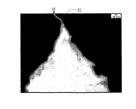
Fig. 7. A SEM image; cross-sectional view of a
niobium oxide nanostructure formed by anodizing niobium
metal under about 25 volts in an electrolyte including
about 1.5 wt. % HF(aq) at room temperature.
Fig. 8. SEM images; side-views of a niobium
oxide nanostructure formed by anodizing niobium metal
under about 25 volts at room temperature in an
CA 02615772 2008-01-17
WO 2007/016310 PCT/US2006/029336
11
electrolyte including about 2.5 wt. % HF(aq); (A) the
side of a conical nanostructure and (B) the top of the
conical nanostructures.
Fig. 9. SEM images; top view showing the growth
of niobium oxide nanostructures formed by anodization.
The nanostructures were formed under about 25 volts at
room temperature in an electrolyte including about 1.5
wt. % HF(aq) for; (A) 2 hours, (B) 3 hours; (C) 4
hours; and (D) 6.5 hours.
Fig. 10. A SEM image; cross-sectional views
illustrating "growth rings" in a niobium oxide micro-
nanostructure formed by anodizing niobium metal under
about 15 volts under room temperature in an electrolyte
including about 1.5 wt. % HF(aq). Fig. 10(A) an image
collected at a relatively low magnification 10(B) and
image collected twice the magnification used to collect
the image in Fig 10(a).
Fig.. 11. A SEM image; top views of a niobium
oxide nanostructures formed by anodizing niobium metal
an electrolyte solution including 1.5 wt. % HF, at room
temperature. The material shown in panel A was formed t
a constant potential of 30 V and the material shown in
panel (B) was formed at 40 volts.
Fig. 12. X-Ray Diffraction (XRD) pattern of a
crystalline niobium oxide film formed by anodizing Nb
metal in the presence of NaF. The oxide was soaked for
16 hours in artificial saliva and this pattern was
collected. Features of the pattern include a
pronounced crystal nanostructure belonging to Nb205 when
indexed (JCPDS# 30-0873) and Hydroxylapatite (HAP)
CA 02615772 2008-01-17
WO 2007/016310 PCT/US2006/029336
12
formation (JCPDS 409-0432) shown marked with an
asterisk.
Fig. 13. X-Ray Diffraction patterns of niobium
oxides formed by anodizing Nb metal and then soaking
the material in artificial saliva before collecting the
patterns. The pattern shown with double lines is of an
oxide formed in the presence of,NaF; the pattern shown
in the solid line was formed in the absence of added
NaF. Only the pattern with the double line shows a
feature, marked with an asterisk that indexes with
(HAP).
Fig. 14. SEM images of niobium oxide crystals in
contact with hydroxyapitie (HAP); (A) image collected
at a relatively low magnification (B) image collected
relatively high magnification.
Fig. 15. Schematic diagrams illustrating elements
of (A) an electron gun and (B) an electron microscope
including an electron gun.
CA 02615772 2008-01-17
WO 2007/016310 PCT/US2006/029336
13
DETAILED DESCRIPTION
For the purposes of promoting an understanding of
the principles of the invention, reference will now be
made to the embodiments illustrated herein and specific
language will be used to describe the same. It will
nevertheless be understood that no limitation of the
scope of the invention is thereby intended. Any
alterations and further modifications in the described
processes, systems or devices, and any further
applications of the principles of the invention as
described herein, are contemplated as would normally
occur to one skilled in the art to which the invention
relates.
Most terms are given their usual and customary
meaning as used in the art to which the various
embodiments are directed. Some terms are clarified as
follows. As used herein the terms "pharmaceutically-
acceptable topical oral carrier," or "topical, oral
carrier," generally means one or more compatible solid
or liquid fillers, diluents or encapsulating substances
that are suitable for topical, oral administration.
The term, "compatible," as used herein, means that
components of the composition are capable of being
commingled without interacting in a manner which would
substantially reduce the composition's stability and/or
efficacy for treating or preventing oral care
conditions such as caries, according to the
compositions and methods of the present invention.
The term "about" generally refers to range of plus
or minus on the order of ten percent of the value the
CA 02615772 2008-01-17
WO 2007/016310 PCT/US2006/029336
14
entire range being on the order of 20 percent of the
relevant value.
A therapeutically effective dosage or amount of a
compound is an amount sufficient to affect a positive
effect on a given medical condition. The affect if not
immediately may, over period of time, provide a
noticeable or measurable effect on a patient's health
and well being.
Unless it specially states otherwise the terms
'structures,' 'nanocones,' 'nanostructures' and
'microstructures' used to describe niobium oxide formed
by anodizing niobium metal in various embodiments of
the invention are used interchangeably.
A number of explanations and experiments are
provided by way of explanation and not limitation. No
theory of how the invention operates is to be
considered limiting whether proffered by virtue of
description, comparison, explanation or example.
With the possible exception of gold, the formation
of oxides on metals is omnipresent under standard
temperature and pressure in the presence of oxygen. A
number of studies have been reported elucidating the
preparation and utility of novel nanoporous metal oxide
nanostructures for applications including catalysis,
sensing, and bio-engineering see, for example, [6-7].
Some of these studies report the formation of
metal oxide nariostructures that have two- and three-
dimensional geometries including pores [9] and tubes,
[10]. These nanostructures may be developed in several
ways including templating [11], anodization [12], and
sol-gel processes [3]. In terms of cost, purity, and
CA 02615772 2008-01-17
WO 2007/016310 PCT/US2006/029336
convenience anodization offers a particularly
attractive means for producing useful metal oxides.
The most popular oxides used to form structures
that have a defined shape include oxides of aluminum
5 and titanium [11, 10]. These particular oxides have
attracted a lot of interest, in part because; they are
relatively easy to prepare. However, oxides of other
metals, such as niobium, are also of interest because
they may have certain advantageous over other more
10 commonly used metal oxides.
Niobium oxide in particular may be of considerable
utility because of its extremely high corrosion
resistance and thermodynamic stability. These
properties render niobium oxide a promising candidate
15 for use in, for example, coatings for improved
osteoblast cell adhesion on artificial implants or for
use in electronic, electrochromic, ferroelectric
devices, sensors and separation columns sand devices.
For additional general discussion of these applications
please see [1, 3, 13].
Despite considerable research on the formation
mechanism, composition, and uses of metal oxides,
relatively little has been reported on the self-
organized morphologies of metal oxides in general and
on niobium oxides in particular [2]. Some recent
studies report the preparation of nanoporous niobium
oxide structures. For a more extensive discussion of
metal oxide nanoporous structures the reader is
directed to [5, 13]. .
The lack of morphological options in forming and
shaping metal oxides such as niobium oxide is impeding
CA 02615772 2008-01-17
WO 2007/016310 PCT/US2006/029336
16
the use and development of metal oxides in promising
material science and medical applications. One aspect
of the invention provides methods for forming self-
organized niobium oxide nanostructures.
One embodiment includes a nano-tipped niobium
oxide nanocones prepared via electrochemical
anodization carried out in the presence of an
electrolyte including an inorganic acid. One inorganic
acid useful as an electrolyte in this process is HF.
Referring now to Fig. 1, a schematic diagram of an
anodization set-up (1) that can be used to produce
various niobium oxides in accordance with some
embodiments of the invention. Device (1) includes: a
power source (2); a layer of copper metal (4) an
electrolyte (6) a layer of niobium metal (10). As the
reaction proceeds a layer of niobium oxide (8)
accumulates on the surface of metal (9).
Referring now to Figs. 2 and 3; both show Energy
Dispersion Spectra of materials, which include niobium.
These materials were formed by anodization of niobium
carried out at a constant potential.
Referring now to Fig. 2, the material analyzed in
Fig. 2 was formed by anodizing niobium metal for 68
min. at 20 volts, 46 degrees C in an electrolyte that
included 100mg of NaF per 100 mL of 2.5 wt. % HF(aq).
This spectrum (22) shows a very distinct peak (24)
identified as niobium.
The material analyzed in Fig. 3 was formed by
anodizing niobium metal for 90 min. at 20 volts, 50
degrees C in an electrolyte that included 200 mg of NaF
CA 02615772 2008-01-17
WO 2007/016310 PCT/US2006/029336
17
per 100 mL of 2.5 wt. % HF(aq). This spectrum (32)
shows a very distinct peak (34) identified as niobium.
Still another embodiment includes niobium oxide
nanostructures formed under anodization conditions
including varying concentration of HF(aq), the presence
and absence of NaF, different anodizing times,
different temperatures, and electrical potentials.
Referring now to Fig. 4; top views of one
embodiment niobium oxide nanostructures formed by
anodizing niobium metal. All of the nanostructures
shown in panels (A) through (D) (40), (43), (46) and
(49) respectively were formed by anodization carried
out at 22 degrees C, in 1.5 wt. % HF(aq).. All showed
distinct peaks (41), (44), (47) and (50); and gaps
(42), (45), (48), (51) between peaks (41), (44), (47)
and (50). All niobium oxide microstructures shown in
Fig, 4 were formed at different constant voltages:
those in panel (A) were formed at 25 volts; those in
panel (H) were formed at 40 volts; those in panel (C)
were formed at 30 volts; and those in panel (D) were
formed at 90 volts. These data indicate that, other
parameters held equal, the size of the niobium
nanocones formed varies with the voltage used.
Referring now to Fig. 7; a SEM image (70) a cross-
sectional view of niobium oxide nanocone structures
(71) formed by anodizing niobium metal. These
nanostructures (71) were formed by anodizing niobium
metal at a constant potential of 25 volts, at room
temperature, in the presence of an electrolyte that
includes 2.5 wt. % HF. Microstructures (71) are in the
generally shape of a nanocone and have: distinct tops
CA 02615772 2008-01-17
WO 2007/016310 PCT/US2006/029336
18
(74); sides (72), a common base (78); and crevices (78)
between individual nanocones (71).
Another embodiment is the use of bioactive niobium
oxides in a variety of medical applications. As
illustrated in Figs. 12, 13 crystalline niobium oxides
formed in the presence of NaF can bind to
hydroxyapatite (HAP). These patterns show a feature
(marked with an asterisk) that is indicative of HAP
when indexed it match with (JCPDS 009-0432).
Bioactive niobium oxides made in accordance with
various embodiments of the invention interacts with
hydroxylapatite. Hydroxylapatite is found in human and
animal, bone, teeth, tooth enamel, and dentin. One form
of hydroxylapatite is represented by the formula
Ca5 (P04) 3(OH) sometimes written as Calo (PO4) 6(OH) 2 .
Referring now to Fig. 14, additional evidence of
crystalline niobium oxide binding with HAP is shown in
SEM images 141 and 144. Referring now to Fig. 14 (A)
crystalline niobium oxide microcone 141 shown in SEM
image 140 was formed by anodizing niobium metal for 90
min. under 20 volts at 50 degrees C in the presence of
an electrolyte comprising 200 mg per mL of NaF in 2.5
wt. % HF (aq). Before image 140 was taken, the
material was immersed in artificial saliva for 19
hours. This induced the formation of HAP crystal (143)
on the niobium oxide crystal nanostructure (141).
Referring now to Fig.14 (b); SEM image (142).
Crystalline niobium oxide microcone (144) was formed by
anodizing niobium metal for 2.5 hours under 20 volts at
46 degrees C in the presence of an electrolyte
comprising 100mg per mL NaF in 2.5 wt. % HF (aq).
CA 02615772 2008-01-17
WO 2007/016310 PCT/US2006/029336
19
Before image (140) was taken the material was immersed
in artificial saliva for 19 hours. This induced the
formation of HAP crystal (146) on the niobium oxide
crystal structure (144).
As illustrated in SEM images Figs 4-11 various
niobium oxides made in accordance with a number of
embodiments have a rough surface. This rough surface
makes for a large surface area and when combined with
the material's affinity for hydroxylapatite (HAP)
implies utility as an interface between teeth, bone and
artificial materials that are intended to interact
strongly with teeth and bone and the like. Still
another embodiment is using of bioactive crystalline
niobium oxides to mend, support, shape, knit, or
' replace elements of bone, teeth and similar tissues in
human and animal patients.
The shape and size of the nanostructures formed
can be readily adjusted by varying the anodization
parameters, such as the thickness of niobium metal
starting material. To a first approximation the thicker
the metal to begin with the higher the conical
structure that can be formed via the anodization
process. Voltage values range of between 15 to about
150 volts can be used. Other useful ranges include
values of between about 15 to about 100 and between
about 15 to about 75 volts.
Temperature also affects that rate of oxide
formation and to some extent the shape of the
nanostructures. Suitable temperatures for carrying out
the anodization reaction range from about -10 degrees
Celsius to about 110 degrees Celsius, other suitable
CA 02615772 2008-01-17
WO 2007/016310 PCT/US2006/029336
ranges include from about to 20 degrees Celsius about
10 degrees Celsius and from about 20 degrees Celsius to
about 90 degrees Celsius.
The anodization reaction can be carried out so
5 long as there is niobium metal to be oxidized. While
the reaction, given sufficient metal, has the potential
to run for days as a practical matter various assays
conditions will likely be adjusted to form suitable
nanostructures in a matter hours.
10 Anodization of Niobium metal to form bioactive
niobium oxides according to various embodiments of the
invention generally include HF(aq.) in the electrolyte.
In some embodiments additional acids may be added to HF
(aq.), including, for example, phosphoric acid.
15 The amount and composition of electrolyte also
influences the size and shape of the nanostructure
formed. Bioactive niobium oxides are formed in the
presence of hydrofluoric acid (HF). Suitable ranges of
HF(aq.) for the process range from about 1 wt. percent
20 to about 15, wt. percent, other useful ranges for HF
include about 2.5 to about 10.0 wt. percent, in one
embodiment the concentration of HF(aq.) in the reaction
is on the order of about 2.5 wt. percent.
The level of salt added to the electrolyte also
influences the rate of the reaction and the shape of
the nanostructures. Any salt with the capacity to
contribute ions to the niobium metal layer and that is
soluble in HF(aq.) can be used in the electrolyte.
Typical salts used include HF and Na2SO4.
One embodiment includes stabilizing the otherwise
fragile niobium oxide nanostructures by covering them
CA 02615772 2008-01-17
WO 2007/016310 PCT/US2006/029336
21
with less brittle materials such as silver, copper or
of alloys of gold and palladium (AuPd). Additional
metals that can be used to coat niobium oxide
nanostructure include, but are not limited to, gold,
platinum, palladium, ruthenium, rhodium, iridium,
silver, rhenium, osmium, nickel, copper, zinc and
alloys thereof.
Still another embodiment includes using these
niobium oxide nanocones in the manufacture of
electrical devices. Devices that may benefit from the
use of such fine tipped nanostructure include but are
not limited to devices illustrated schematically in
Fig. 15.
Fig. 15 (A) shows an electron gun (151) that can
be used in photoelectric displays that are used in
photoelectric displays. A typical electron gun of this
form includes: a filament (153); a cathode (157); an
anode (159); current through the filament (153) creates
an electron cloud (155) directly above a gap between
cathode (157) and anode (159). The effect of this gap
is to accelerate and focus the electrons in cloud (155)
to from the spray of electrons (161).
Additional uses for niobium oxide conical
microstructures formed according to various embodiments
include using them in the manufacture of devices for
focusing electron beams in analytical instruments.
Such instruments include, but are not limited to,
electron microscopes such as scanning electron
microscopes.
Referring now to Fig. 15 (B) a schematic
representation of an electron focusing device (170)
CA 02615772 2008-01-17
WO 2007/016310 PCT/US2006/029336
22
used in an electron microscope. Various parts include:
a filament (171); a source of negative potential
referred to a Wehnelt Cap (173); a space charge (174);
an anode plate (175). Briefly, an electrical charge to
filament (171) produces a stream of electrons that are
focused by a gap (177) in Wehnelt Cap (173); this
produces a beam of electrons (179) which is accelerated
towards a gap (181) in anode plate (175).
Referring still to Fig. 15(B) the resolution of
these types of devices is at least in part dependent
upon.the fineness of the electrical stream which is in
turn at least partially dependent upon the filament
(171) used to construct the electron gun (170).
Accordingly, nano-tipped, conical nanostructures
comprising niobium oxide nanostructures can be used to
build electron microscopes with very high resolution.
Still another use for these nanostructures is as
filaments in the construction of high resolution photo-
electronic displays.
Another embodiment is to use niobium oxide
nanostructures in the construction of sensors. The
nanostructures can be coated with various materials
that selectively interact with at least one component
of a mixture of gasses or liquids. As samples are
25, placed in contact with the surface a signal is
generated when at least one component in the sample
interacts with the surface of the sensor. Suitable
coating depending upon the analyte include metals such
as platinum, palladium rhodium, ruthenium, iridium,
gold, silver, rhenium, osmium, nickel, copper, zinc and
CA 02615772 2008-01-17
WO 2007/016310 PCT/US2006/029336
23
alloys of these and other metals as well as oxides of
the same.
In still another embodiment niobium oxide
nanostructures are coated with materials that
selectively interact with specific organisms or
components of organisms. In one embodiment the
nanostructure may be coated with materials that
selectively interact with structures on the surface of
pathogenic bacteria, virus, molds, fungi, protozoa and
the like.
In one embodiment the surface is coated with
molecules that hybridize either directly or indirectly
with nucleic acid polymers such as DNA or RNA. Direct
binding can be accomplished by coating the surface of
the nanostructure with segments of nucleic acid polymer
that are complimentary to target sequences in a given
sample, under hybridize to at least one DNA or RNA
sequence in the sample under a given set of assay
conditions. Indirect binding may be accomplished by
coating the surface of the sensor with a material that
preferentially binds to tags or labels placed attached
to at least one nucleic acid polymer in the sample. In
one embodiment niobium oxide nanostructures are coated
with at least molecule that exhibits a change in
fluorescence when it interacts with a given sequence of
a nucleic acid polymer such as DNA and/or RNA.
In still another embodiment the nanostructures of
niobium oxide are coated with materials that
selectively or preferentially interact with biomolecues
such as amino acids, peptides, polypeptides, proteins,
sugars, polysaccharides, nucleic acids, signally
CA 02615772 2008-01-17
WO 2007/016310 PCT/US2006/029336
24
molecules, neurotransmitters, hormones, fatty acids,
alcohols, antibodies and the like.
In still another embodiment the surface is coated
with materials that selectively interact with various,
metals, metal alloys, metal oxides, other inorganic
molecules and organic molecules.
In another embodiment niobium oxide nanostructures
used in the construction of devices used in
chromatography, the separation of components of various
mixtures based on their physical and or chemical
properties. Such devices include, but are not limited
to, gas chromatography can liquid chromatography
columns. The devices can be comprised of niobium oxide
nanostructures that provide a large surface area and
interact with component of a given gas or liquid
sample. In still another embodiment the nanostructures
are coated with materials that differentially or
selectively interact with at least one component of a
mixture of compounds in a given sample. Various
coatings include, but are not limited to, metals, metal
oxides, antibodies, and the like.
Metals, metal alloys and some metal oxides may be
applied to the surface of the niobium nanostructures by
techniques including, but not limited to, sputtering,
electron spray, electron laser desorption, and
electrolysis.
In still another embodiment niobium oxide
nanostructures are used in the construction of
catalysts. In some embodiment the surface of the
nanostructure is coated with a metal or mixture of
metals that catalyze various reactions. Metal suitable
CA 02615772 2008-01-17
WO 2007/016310 PCT/US2006/029336
for this use include, but are not limited to, platinum,
palladium, rhodium, ruthenium, iridium, gold, silver,
rhenium, osmium, nickel, copper, zinc and alloys of
these and other metals as well as some oxides of the
5 same.
As illustrated in various examples throughout the
application, the bioactive niobium oxide nanostructures
disclosed in various embodiments also readily interacts
with hydroxylapatite, (HAP) a fundamental component in
10 the construction of human teeth and bones..
Niobium oxide nanostructures according to these
embodiments may be added to various preparations for
use in the care and treatment of teeth and bones in the
oral cavity. For example, they may be added to
15 desensitizers wherein their ability to bind to teeth
and hydroxylapatite (HAP) in the presence of saliva can
be used to treat teeth which are exceptionally
sensitive to various chemicals and sensations
including, for example, temperature, sweetness, etc.
20 In another embodiment, bioactive niobium oxides of
some embodiments are incorporated into dentifrices in
the form of a gel, paste, strip, rinse, gum or varnish;
typically the oxide is admixed with various suitable
dental surfactants. Various components of dental
25 surfactants and other dentifrices that can be used in
combination with niobium oxide microstructures of
various embodiments are as follows.
The carriers of the present invention may include
the usual and conventional components of toothpastes
(including gels and gels for subgingival application),
CA 02615772 2008-01-17
WO 2007/016310 PCT/US2006/029336
26
mouth rinses, mouth sprays, and more many of these are
more fully described, hereinafter.
The choice of a carrier to be used is generally
determined by the way the composition is to be
introduced into the oral cavity. If a tooth paste
(including tooth gels, etc.) is to be used, then a
"toothpaste carrier" is chosen and may include for,
example, abrasive materials, sudsing agents, binders,
humectants, flavoring and sweetening agents and the
like as disclosed in, for example, U.S. Pat. No.
3,988,433, to Benedict, issued on October 25, 1976,
which is incorporated herein by reference. If a mouth
rinse is to be used, then a "mouth rinse carrier" is
chosen, such as water, flavoring and sweetening agents
as disclosed in, for example, U.S. Pat. No. 3,988,433
issued to Benedict, and incorporated herein by
reference in its entirety. Similarly, if a mouth spray
is to be used, then a "mouth spray carrier" is chosen.
If a sachet is to be used, then a "sachet carrier" is
chosen (e.g., sachet bag, flavoring and sweetening
agents). If a subgingival gel is to be used (for
delivery of the active material into the periodontal
pockets, or around the periodontal pockets, then the
material may be combined with a, "subgingival gel
carrier". Suitable subgingival carries include those
disclosed in U.S. Pat. No. 5,198,220, Damani, issued
Mar. 30, 1993, P&G, U.S. Pat. No. 5,242,910, Damani,
issued Sep. 7, 1993, all of which are incorporated
herein by reference in their entirety. Carriers
suitable for the preparation of compositions of the
present invention are well known in the art. Their
CA 02615772 2008-01-17
WO 2007/016310 PCT/US2006/029336
27
selection will depend on secondary considerations such
as mouth feel, taste, cost, shelf stability and the
like.
Preferred compositions for use in various
embodiments may be in the form of dentifrices, such as
toothpastes, tooth gels, tooth polishes and tooth
powders. Components of such toothpaste and tooth gels
generally include one or more of a dental abrasive
(from about 10% to about 50%), a surfactant (from about
0.5% to about 10%), a thickening agent (from about 0.1%
to about 5%), a humectant (from about 10% to about
55%), a flavoring agent (from about 0.04% to about 2%),
a sweetening agent (from about 0.1% to about 3%), a
coloring agent (from about 0.01% to about 0.5%) and
water (from about 2% to about 450). Such toothpaste or
tooth gel may also include one or more of an additional
anticaries agent (from about 0.05% to about 10%
additional anticaries agent), and an anticalculus agent
(from about 0.1% to about 130). Tooth powders, of
course, contain substantially all non-liquid
components.
Other preferred compositions for use in various
embodiments include, for example, non-abrasive gels,
including subgingival gels. Gel compositions commonly
include a thickening agent (from about 0.1% to about
20%), a humectant (from about 10% to about 55%), a
flavoring agent (from about 0.04% to about 2%), a
sweetening agent (from about 0.1% to about 3%), a
coloring agent (from about 0.01% to about 0.5%), water
(from about 2% to about 45%), and may comprise an
additional anticaries agent (from about 0.05% to about
CA 02615772 2008-01-17
WO 2007/016310 PCT/US2006/029336
28
10% of additional anticaries agent), and an
anticalculus agent (from about 0.1% to about 13%).
Other preferred compositions for use in various
embodiments may include, for example, mouthwashes,
mouth rinses, and mouth sprays. Components of such
mouthwashes and mouth sprays typically include one or
more of water (from about 45% to about 95%), ethanol
(from about 0% to about 25%), a humectant (from about
0% to about 50%), a surfactant (from about 0.01% to
about 7%), a flavoring agent (from about 0.04% to about
2%), a sweetening agent (from about 0.1% to about 3%),
and a coloring agent (from about 0.001% to about 0.5%).
Such mouthwashes and mouth sprays may also include one
or more additional anticaries agents present, for
example, from about 0.05% to about of additional
anticaries agent, and an anticalculus agent present,
for example, from about 0.1% to about 13%.
Other preferred compositions for use with various
embodiments include, for example, dental solutions.
Components of such dental solutions generally may
include one or more of water present from about 90% to
about 99%, preservative present from about 0.01% to
about 0.5%, thickening agent present from 0% to about
5%, flavoring agent present from about 0.04% to about
2%, sweetening agent present from about 0.1% to about
3%, and surfactant present in such compositions from
about 0% to about 5%.
Types of carriers which may be included in
compositions of the present invention, along with
specific non-limiting examples, abrasives, sudsing
agents many of which are surfactants, thickening
CA 02615772 2008-01-17
WO 2007/016310 PCT/US2006/029336
29
agents, humectants, flavoring and sweetening agents,
anticalculus agents, alkali metal bicarbonate salts,
and miscellaneous carriers.
Dental abrasives useful in the topical, oral
carriers of the compositions of various embodiments
include many different materials. Various suitable
materials are preferably materials that are compatible
within the composition of interest and one that do not
excessively abrade dentin. Suitable abrasive materials
include, for example, silicas including gels and
precipitates, insoluble sodium polymetaphosphate,
hydrated alumina, calcium carbonate, dicalcium
orthophosphate dihydrate, calcium pyrophosphate,
tricalcium phosphate, calcium polymetaphosphate, and
resinous abrasive materials such as particulate
condensation products of urea and formaldehyde.
Another class of abrasives for use in various
embodiments include, for example, particulate thermo-
setting polymerized resins as described in U.S. Pat.
No. 3,070,510 issued to Cooley & Grabenstetter on Dec.
25, 1962. Suitable resins include, for example,
melamines, phenolics, ureas, melamine-ureas, melamine-
formaldehydes, urea-formaldehyde, melamine-urea-
formaldehydes, cross-linked epoxides, and cross-linked
polyesters. Various mixtures of various abrasives may
also be used.
Silica dental abrasives of various types may be
used in some embodiments because they provide
exceptional dental cleaning and polishing performance
without unduly abrading tooth enamel or dentine. The
silica abrasive polishing materials described herein,
CA 02615772 2008-01-17
WO 2007/016310 PCT/US2006/029336
as well as other abrasives, generally have an average
particle size ranging between about 0.1 to about 30
microns, and preferably from about 5 to about 15
microns although materials with differing sizes may
5 also be used in various embodiments. The abrasive can
be precipitated silica or silica gels such as the
silica xerogels described in U.S. Pat. No. 3,538,230
issued to Pader et al., on Mar. 2, 1970, and, U.S. Pat.
No. 3,862,307, issued to DiGiulio on Jan. 21, 1975,
10 both of which incorporated herein by reference in their
entirety. Preferred are the silica xerogels marketed
under the trade name "Syloid" by the W.R. Grace &
Company, Davison Chemical Division. Also preferred are
the precipitated silica materials such as those
15 marketed by the J. M. Huber Corporation under the trade
name, Zeodent®, particularly the silica carrying
the designation Zeodent 119® For a more thorough
discussion and listing of types of silica dental
abrasives useful in the toothpastes the reader is
20 directed to see, U.S. Pat. No. 4,340,583, issued to
Wason on Jul. 29, 1982, and incorporated herein by
reference in its entirety. The abrasive in the
toothpaste compositions described herein is generally
present at a level of from about 6% to about 70% by
25 weight of the composition. Preferably, toothpastes may
contain from about 10% to about 50% of abrasive, by
weight of the composition.
One type of precipitated silica for use in various
embodiments is disclosed in U.S. Pat. No. 5,603,920,
30 issued on Feb. 18, 1997; U.S. Pat. No. 5,589,160,
issued Dec. 31, 1996; U.S. Pat. No. 5,658,553, issued
CA 02615772 2008-01-17
WO 2007/016310 PCT/US2006/029336
31
Aug. 19, 1997; U.S. Pat. No. 5,651,958, issued Jul. 29,
1997, all of which incorporated herein by reference in
their entirety.
A variety of mixtures of abrasives can also be
used. All of the above patents regarding dental
abrasives are incorporated herein by reference. The
total amount of abrasive in dentifrice compositions in
various embodiments may generally range from about 6%
to about 70% by weight; commonly toothpastes contain
from about 10% to about 50% of abrasives, by weight of
the composition. Solution, mouth spray, mouthwash and
non-abrasive gel compositions of the subject invention
typically contain no abrasive, although abrasive
materials may be added to such compositions.
Suitable for use in various embodiments include
sudsing agents that are reasonably stable and form foam
throughout a wide pH range. Sudsing agents include, but
are not limited to, nonionic, anionic, amphoteric,
cationic, zwitterionic, synthetic detergents, and
mixtures thereof. Many suitable nonionic and amphoteric
surfactants are disclosed in U.S. Pat. No. 3,988,433
issued to Benedict on Oct. 26, 1976 and U.S. Pat. No.
4,051,234, issued to Gieske et al. on Sep. 27, 1977.
Many suitable nonionic surfactants are disclosed by
Agricola et al., U.S. Pat. No. 3,959,458 to Agicola et
al., issued on May 25, 1976, both of which are
incorporated herein by reference in their entirety.
Various nonionic and amphoteric surfactants may be
used in various embodiments. As used herein, nonionic
surfactants that may be used in various embodiments can
be broadly defined as compounds produced by the
CA 02615772 2008-01-17
WO 2007/016310 PCT/US2006/029336
32
condensation of alkylene oxide groups (hydrophilic in
nature) with an organic hydrophobic compound which may
be aliphatic or alkyl-aromatic in nature. Examples of
suitable nonionic surfactants include, but are not
limited to, poloxamers (sold under trade name
Pluronic), polyoxyethylene sorbitan esters (sold under
trade name Tweens), fatty alcohol ethoxylates,
polyethylene oxide condensates of alkyl phenols,
products derived from the condensation of ethylene
oxide with the reaction product of propylene oxide and
ethylene diamine, ethylene oxide condensates of
aliphatic alcohols, long chain tertiary amine oxides,
long chain tertiary phosphine oxides, long chain
dialkyl sulfoxides, and mixtures of such materials.
As used herein various amphoteric surfactants that
can be used in various embodiments can be broadly
described as derivatives of aliphatic secondary and
tertiary amines in which the aliphatic radical can be a
straight chain or branched and wherein one of the
aliphatic substituents contains from about 8 to about
18 carbon atoms and one contains an anionic water-
solubilizing group, e.g., carboxylate, sulfonate,
sulfate, phosphate, or phosphonate. Other suitable
amphoteric surfactants are betaines, specifically
cocamidopropyl betaine. Mixtures of amphoteric
surfactants can also be used in various embodiments.
Various embodiments may typically comprise a
nonionic, amphoteric, or combination of nonionic and
amphoteric surfactant each at a level of from about
0.025% to about 5%, in another embodiment from about
0.05% to about 4%, and in even another embodiment from
CA 02615772 2008-01-17
WO 2007/016310 PCT/US2006/029336
33
about 0.1% to about 3% by weight, although other ranges
of such materials may be present in various
embodiments.
As used herein, anionic surfactants that can be
added to various embodiments include water-soluble
salts of alkyl sulfates having from 8 to 20 carbon
atoms in the alkyl radical (e.g., sodium alkyl sulfate)
and the water-soluble salts of sulfonated
monoglycerides of fatty acids having from 8 to 20
carbon atoms. Sodium lauryl sulfate and sodium coconut
monoglyceride sulfonates are examples of anionic
surfactants of this type. Other suitable anionic
surfactants are sarcosinates, such as sodium lauroyl
sarcosinate, taurates, sodium lauryl sulfoacetate,
sodium lauroyl isethionate, sodium laureth carboxylate,
and sodium dodecyl benzenesulfonate. Various mixtures
of anionic surfactants can also be employed. Some
embodiments typically comprise an anionic surfactant at
a level of from about 0.025% to about 9%, and in
another embodiment from about 0.05% to about 7%, and in
still another embodiment from about 0.1% to about 5% by
weight.
Toothpastes and gels typically include a
thickening agent added to the compound to create a
desirable consistency, to provide desirable release
characteristics when used, to increase shelf stability,
and to increase the overall stability of the
composition, etc. Preferred thickening agents that may
be used in various embodiments include, but are not
limited to, carboxyvinyl polymers, carrageenan,
hydroxyethyl cellulose, laponite and water soluble
CA 02615772 2008-01-17
WO 2007/016310 PCT/US2006/029336
34
salts of cellulose ethers such as sodium
carboxymethylcellulose and sodium carboxymethyl
hydroxyethyl cellulose. Natural gums such as gum
karaya, xanthan gum, gum arabic, and gum tragacanth can
also be used. Colloidal magnesium aluminum silicate or
finely divided silica may be added to further improve
the texture of the composition.
Thickening agents may include, with the exception
of polymeric polyether compounds, e.g., polyethylene or
polypropylene oxide (M.W. 300 to 1,000,000), capped
with alkyl or acyl groups containing 1 to about 18
carbon atoms.
A preferred class of thickening or gelling agents
for use in various embodiments includes a class of
homopolymers of acrylic acid cross linked with an alkyl
ether of pentaerythritol or an alkyl ether of sucrose,
or carbomers. Carbomers are commercially available from
B. F. Goodrich as the Carbopol.RTM series. Additional
carbopols that may be included in various embodiments
includes Carbopol 934, 940, 941, 956, and mixtures
thereof.
Subgingival gel carrier for use in or around
periodontal pockets periodontal pockets may include
copolymers of lactide and glycolide monomers. A typical
copolymer for use in these compositions has a molecular
weight in the range of from about 1,000 to about
120,000 these values are average numbers for the
molecular weights of the various components. For a
more through discussion and listing of such polymers
the reader is directed to see: U.S. Pat. No. 5,198,220,
issued to Damani, on Mar. 30, 1993; U.S. Pat. No.
CA 02615772 2008-01-17
WO 2007/016310 PCT/US2006/029336
5,242,910, issued to Damani, on Sep. 7, 1993; and U.S.
Pat. No. 4,443,430, issued to Mattei, on Apr. 17, 1984,
all of which are incorporated herein by reference in
their entirety.
5 Thickening agents in an amount fr m about 0.1% to
about 15%, or from about 0.2% to about 6%, in another
embodiment from about 0.4% to about 5%, by weight of
the total toothpaste or gel composition, can be used.
Higher concentrations can be used for sachets, non-
10 abrasive gels and subgingival gels.
Various embodiments may include a humectant, an
additive that helps to keep various compositions such
as toothpaste from hardening upon exposure to air.
Additional benefits from the addition of hemectants
15 include improved moth feel including an enhanced moist
feel to the mouth. Some hemectants may also impart a
desirable sweet flavor to various compositions. A
typical humectant, on a pure humectant basis, generally
comprises from about 0% to about 70%, preferably from
20 about 5% to about 25%, by weight of the compositions
herein. Suitable humectants for use in various
embodiments include, but are not limited to, edible
polyhydric alcohols such as glycerin, sorbitol,
xylitol, butylene glycol, polyethylene glycol, and
25 propylene glycol, especially sorbitol and glycerin.
Various embodiments may also include flavoring
agents. Suitable flavoring agents for use in various
embodiments may include, for example, oil of
wintergreen, oil of peppermint, oil of spearmint, clove
30 bud oil, menthol, anethole, methyl salicylate,
eucalyptol, 1-menthyl acetate, sage, eugenol, parsley
CA 02615772 2008-01-17
WO 2007/016310 PCT/US2006/029336
36
oil, oxanone, alpha-irisone, marjoram, lemon, orange,
propenyl guaethol, cinnamon, vanillin, thymol,
linalool, cinnamaldehyde glycerol acetal known as CGA,
and mixtures thereof. Flavoring agents are generally
used in the compositions at levels of from about 0.001%
to about 5%, by weight of the composition.
Sweetening agents which can be added to various
embodiments include, but are not limited to, sucrose,
glucose, saccharin, dextrose, levulose, lactose,
mannitol, sorbitol, fructose, maltose, xylitol,
saccharin salts, thaumatin, aspartame, D-tryptophan,
dihydrochalcones, acesulfame and cyclamate salts,
especially sodium cyclamate and sodium saccharin, and
mixtures thereof. A typical composition may include
from about 0.1% to about 10% of these agents, in
another embodiment from about 0.1% to about 1%, by
weight of the composition.
Various embodiments may include coolants,
salivating agents, warming agents, numbing agents and
analgesics. Typically, agents are included in the
compositions at a level of from about 0.001% to about
10%, in another embodiment from about 0.1% to about 1%,
by weight of the composition.
Coolants can be any of a wide variety of materials
including materials such as carboxamides, menthol,
ketals, diols, and mixtures thereof. Various coolants
especially useful the present compositions are
paramenthan carboxyamide agents such as N-ethyl-p-
menthan-3-carboxamide, known commercially as "WS-3",
N,2,3-trimethyl-2-isopropylbutanamide, known as "WS-
23," and mixtures thereof. Additional useful coolants
CA 02615772 2008-01-17
WO 2007/016310 PCT/US2006/029336
37
may be selected from the group consisting of menthol,
3-1-menthoxypropane-l,2-di- ol known as TK-10
manufactured by Takasago, menthone glycerol acetal
known as MGA manufactured by Haarmann and Reimer, and
menthyl lactate known as Frescolat® manufactured by
Haarmann and Reimer. The terms menthol and menthyl as
used herein include dextro- and levorotatory isomers of
these compounds and racemic mixtures thereof. TK-10 is
described in U.S. Pat. No. 4,459,425, Amano et al.,
issued Jul. 10, 1984. WS-3 and other agents are
described in U.S. Pat. No. 4,136,163, Watson, et al.,
issued Jan. 23, 1979; the disclosures of both are
herein incorporated by reference in their entirety.
Salivating agents that may be added to various
embodiments include Jambu® manufactured by
Takasago. Typical warming agents that may be added
include, for example, capsicum and nicotinate esters,
such as benzyl nicotinate. Preferred numbing agents
include benzocaine, lidocaine, clove bud oil, and
ethanol.
Various embodiments may include an anticalculus
agent, for example, a pyrophosphate ion source from a
pyrophosphate salt. The pyrophosphate salts useful in
the present compositions include the dialkali metal
pyrophosphate salts, tetraalkali metal pyrophosphate
salts, and mixtures thereof. Disodium dihydrogen
pyrophosphate (Na2H2P207),
tetrasodium pyrophosphate (Na4P207), and
tetrapotassium pyrophosphate (K4P207) in
their unhydrated as well as hydrated forms are the
preferred species.. In various embodiments at least one
CA 02615772 2008-01-17
WO 2007/016310 PCT/US2006/029336
38
pyrophosphate salt may be present in one of three ways:
predominately dissolved, predominately undissolved, or
a mixture of dissolved and undissolved pyrophosphate.
Compositions comprising predominately dissolved
pyrophosphate refer to compositions where at least one
pyrophosphate ion source is in an amount sufficient to
provide at least about 1.0% free pyrophosphate ions.
The amount of free pyrophosphate ions may range from
about 1% to about 15%, in another embodiment from about
1.5% to about 10%, and in still another embodiment from
about 2% to about 6%. Free pyrophosphate ions may be
present in a variety of protonated states depending on
the pH of the composition.
Compositions comprising predominately undissolved
pyrophosphate commonly refer to compositions that
include no more than about 20% of the total
pyrophosphate salt dissolved in the composition,
preferably less than about 10% of the total
pyrophosphate dissolved in the composition. Tetrasodium
pyrophosphate salt is the preferred pyrophosphate salt
in these compositions. Tetrasodium pyrophosphate may be
the anhydrous salt form or the decahydrate form, or any
other species stable in solid form in the dentifrice
compositions. The salt is in its solid particle form,
may be in its crystalline and/or amorphous state, with
the particle size of the salt preferably being small
enough to be aesthetically acceptable and readily
soluble during use. The amount of pyrophosphate salt
useful in making these compositions is any amount
effective to help control tartar; these amounts
generally ranges from about 1.5% to about 15%, in
CA 02615772 2008-01-17
WO 2007/016310 PCT/US2006/029336
39
another embodiment from about 2% to about 10%, and in
still another embodiment the amount ranges from about
3% to about 8%, by weight of the dentifrice
composition. Various embodiments may also include a
mixture of dissolved and undissolved pyrophosphate
salts. Any of the aforementioned pyrophosphate salts
may be used.
Various pyrophosphate salts are described in more
detail in Kirk & Othmer, Encyclopedia of Chemical
Technology, Third Edition, Volume 17, Wiley-
Interscience Publishers (1982), incorporated herein by
reference in its entirety, including all references
incorporated therein into Kirk & Othmer.
Optional agents to be used in place of or in
combination with the pyrophosphate salt include
materials such as synthetic anionic polymers, including
polyacrylates and copolymers of maleic anhydride or
acid and methyl vinyl ether (e.g., Gantrez), as
described, for example, in U.S. Pat. No. 4,627,977, to
Gaffar et al., the disclosure of which is incorporated
herein by reference in its entirety; as well as, e.g.,
polyamino propoane sulfonic acid (AMPS), zinc citrate
trihydrate, polyphosphates (e.g., tripolyphosphate;
hexametaphosphate), diphosphonates (e.g., EHDP; AHP),
polypeptides (such as polyaspartic and polyglutamic
acids), and mixtures thereof.
Various embodiments may also include alkali metal
bicarbonate salts. Typically, alkali metal bicarbonate
salts may be soluble in water and unless stabilized,
they tend to release carbon dioxide in an aqueous
system. Sodium bicarbonate, also known as baking soda,
CA 02615772 2008-01-17
WO 2007/016310 PCT/US2006/029336
is an alkali metal bicarbonate salt commonly used in
compositions intended for use oral hygiene and
medicines. Various embodiments may include at least one
alkali metal bicarbonate salt in a range from about
5 0.5% to about 30%, or in a range of from about 0.5% to
about 15%, and in some cases in a range from about 0.5%
to about 5% of the weight of the composition.
Water employed in the preparation of commercially
suitable oral compositions should preferably be of low
10 ion content and free of organic impurities. Water
generally comprises from about 5% to about 70%, and in
another embodiment from about 20% to about 50%, by
weight of the composition herein. These amounts of
water include the free water which is added plus that
15 which is introduced with other materials, such as with
sorbitol.
Titanium dioxide may also be added to the present
composition. Titanium dioxide is a white powder which
adds opacity to the compositions. Titanium dioxide
20 generally comprises from about 0.25% to about 5% by
weight of the dentifrice compositions.
Antimicrobial antiplaque agents may also by
optionally present in oral compositions. Such agents
may include, but are not limited to, triclosan, 5-
25 chloro-2-(2,4-dichlorophenoxy)-phenol, as described in
The Merck Index, 11th ed. (1989), pp. 1529 (entry no.
9573) in U.S. Pat. No. 3,506,720, and in European
Patent Application No. 0,251,591 of Beecham Group, PLC,
published Jan. 7, 1988; chlorhexidine (Merck Index, no.
30 2090), alexidine (Merck Index, no. 222; hexetidine
(Merck Index, no. 4624); sanguinarine (Merck Index, no.
CA 02615772 2008-01-17
WO 2007/016310 PCT/US2006/029336
41
8320); benzalkonium chloride (Merck Index, no. 1066);
salicylanilide (Merck Index, no. 8299); domiphen
bromide (Merck Index, no. 3411); cetylpyridinium
chloride (CPC) (Merck Index, no. 2024;
tetradecylpyridinium chloride (TPC); N-tetradecyl-4-
ethylpyridinium chloride (TDEPC); octenidine;
delmopinol, octapinol, and other piperidino
derivatives; nicin preparations; zinc/stannous ion
agents; antibiotics such as augmentin, amoxicillin,
tetracycline, doxycycline, minocycline, and
metronidazole; and analogs and salts of the above
antimicrobial antiplaque agents. If present, the
antimicrobial antiplaque agents generally comprise from
about 0.1% to about 5% by weight of the compositions of
the present invention.
Anti-inflammatory agents may also be present in
the oral compositions of the present invention. Such
agents may include, but are not limited to, non-
steroidal anti-inflammatory agents such as aspirin,
ketorolac, flurbiprofen, ibuprofen, naproxen,
indomethacin, aspirin, ketoprofen, piroxicam and
meclofenamic acid, and mixtures thereof. If present,
the anti-inflammatory agents generally comprise from
about 0.001% to about 5% by weight of the compositions
of the present invention. Ketorolac is described in
U.S. Pat. No. 5,626,838, issued May 6, 1997,
incorporated herein by reference in its entirety.
Other optional agents include synthetic anionic
polymeric polycarboxylates being employed in the form
of their free acids or partially or fully neutralized
water soluble alkali metal (e.g. potassium and
CA 02615772 2008-01-17
WO 2007/016310 PCT/US2006/029336
42
preferably sodium) or ammonium salts and are disclosed
in U.S. Pat. No. 4,152,420 to Gaffar, U.S. Pat. No.
3,956,480 to Dichter et al., U.S. Pat. No. 4,138,477 to
Gaffar, U.S. Pat. No. 4,183,914 to Gaffar et al., and
U.S. Pat. No. 4,906;456 to Gaffar et al., all of which
are incorporated herein by reference in their entirety.
Typical ratios are about 1:4 to 4:1 copolymers of
maleic anhydride or acid with another polymerizable
ethylenically unsaturated monomer, including methyl
vinyl ether (methoxyethylene) having a molecular weight
(M.W.) of about 30,000 to about 1,000,000. These
copolymers are available for example as Gantrez (AN 139
(M.W. 500,000), A.N. 119 (M.W. 250,000) and preferably
S-97 Pharmaceutical Grade (M.W. 70,000), of GAF
Corporation.
Some embodiments selectively include H-2
antagonists including compounds disclosed in U.S. Pat.
No. 5,294,433, Singer et al., issued Mar. 15, 1994,
which is herein incorporated by reference in its
entirety.
Again, at least in part because to their large and
uniform surface area the niobium oxides made in
accordance with some embodiments of the invention, are
useful as coatings in various medical devices, where it
is important to promote and intimate contact between
the medical devices and, for example, various bone
structures. In such applications, they would be
readily used in the coating or constructions of screws,
clamps, bolts, staples, plates, pins, bars, straps and
the like. The presence of niobium oxide nanostructures
made in accordance with various embodiments of this
CA 02615772 2008-01-17
WO 2007/016310 PCT/US2006/029336
43
invention and the surface of these devices and its
inherent ability to react with hydroxyl appetite will
promote the formation of strong bonds between the
implanted device and the surrounding bone tissue. They
may find adventitious use in the treatment of diseased,
destroyed, damaged, malformed or missing bone and/or
components of teeth.
Niobium oxide nanostructures in accordance with
various embodiments of the invention are remarkably
uniform and can be readily made in a variety of
different surface areas by adjusting perimeters such as
electrolyte strength, ionic strength, temperature,
potential difference, etc. according to various
embodiments of the invention. Niobium oxides made in
accordance with various embodiments can have a huge,
relatively uniform surface area and they are stable at
high temperatures, these physical properties increase
their utility in applications such as high temperature
catalysis and gas chromatography. Similarly, the
niobium oxide nanostructures may be coated with any of
a number of different catalysts and used in chemical
reactions that take place in either the gaseous or
liquid phase.
Typical tip widths can range from about 30 nm to
about 400 nm; other ranges include from about 40 nm to
about 300 nm, and from about 40 nm to about 100 nm.
Nanocone (nanostructure) heights are theoretically
constrained only by the thickness of the starting
material. Creating higher nanostructures requires
longer anodization times or more vigorous anodization
conditions for example, higher voltages, higher
CA 02615772 2008-01-17
WO 2007/016310 PCT/US2006/029336
44
electrolyte concentrations, temperature adjustments and
the like. Niobium oxide is also soluble in HF(aq.);
this tends to limit the height of nanostructures that
can be formed in the process, irrespective of the
thickness of the starting niobium metal.
Typical niobium oxide nanostructures formed in
accordance with various embodiments of the invention
have heights in the range of about 4 microns to about
60 microns; another range in nanostructure height is
between about 6 to about 50 microns.
Niobium oxides made in accordance with some
embodiments of the invention can be milled to desired
particle sizes. Various milling processes that can be
used to mill the oxide include, but are not limited to,
bead milling, hammer milling, grating, grinding, and
the like.
The uniform shape of the niobium oxide
nanostructures readily lends itself to a variety of
uses that require high surface area and uniform shape.
For example, the niobium oxide nanostructures may be
used in the production of sensors in which niobium
oxide interacts with at least one component in a sample
mixture of gases or liquids. In still another
embodiment the niobium oxide nanostructure is coated
with a material that selectively interacts with at
least one component in a sample of gas or liquid.
In one embodiment the nanostructures of the
current invention are coated with materials that
hybridize to specific sequences of DNA.
In still another embodiment the nanostructures are
coated with materials that bind to tags or labels
CA 02615772 2008-01-17
WO 2007/016310 PCT/US2006/029336
placed on targeted DNA molecules. Such sensors can be
used in the identification, quantification or
separation of specific DNA sequences in a given sample.
Still other embodiments include niobium oxide
5 nanostructures derivatized or coated with materials
such that they differentially interact with bio-
molecules including, but not limited to, RNA,
polysaccharides, polypeptides, signaling molecules,
cell surface markers, hormones, pathogenic organisms,
10 cancer cells and the like.
In one embodiment the niobium oxide nanocones are
modified or coated with a material that changes
fluorescence when it contact certain nucleic acid
polymers such as DNA or RNA.. This signal can be
15 detected and use to monitor the presence and/or amount
of DNA and/or RNA in a given sample.
Niobium oxides nanostructures can be used in the
construction of chromatographic device, for example in
gas chromatography or liquid chromatography columns. In
20 some embodiments the niobium oxide may selectively
interacts with components of the mixture.
Alternatively, niobium oxide nanostructures can be
coated with material or that selectively interact with
various components of the mixtures. Such devices can be
25 used separation various components in a mixture of
compounds.
Niobium oxide nanostructures disclosed in various
embodiments can be used in catalyst construction. For
example, the surfaces of niobium oxide nanostructures
30 coated with catalysts, increase the reaction rate of
reactants contacted with the catalytic surfaces.
CA 02615772 2008-01-17
WO 2007/016310 PCT/US2006/029336
46
Various catalysts that can be coated or layered onto
the niobium oxide nanostructures include, but are not
limited to precious metals catalysts such as palladium,
platinum and the like. Similarly, the niobium oxides
may be coated with any of a number of different
catalysts and used in chemical reactions that take
place in either the gaseous or liquid phase.
EXPERIMENTAL
For the purpose of promoting further understanding
and appreciation of the present invention and its
advantages, the following examples are provided. It
will be understood, however, that these examples are
illustrative and not limiting in any fashion.
EXPERIMENT 1
A section of 99.8% pure niobium foil 0.25 mm thick
was purchased from Aldrich and HF acid (48% by assay)
was obtained from Fisher Scientific. The niobium metal
was rinsed with acetone and ethanol and cut into one
centimeter wide strips and the acid was diluted with
appropriate amounts of deionized water to achieve 1.5
and 2.5 wt. % concentration. A schematic of the
electrochemical anodization system used can be found in
Figure 1.
The electrochemical process is driven by a
Sorensen DLM 300-2 power supply that connects to copper
and niobium metal electrodes. Contained in a Nalgene
130 mL beaker, the electrodes extend partially into the
magnetically agitated electrolyte. The anodization
process of the niobium metal was performed under a
CA 02615772 2008-01-17
WO 2007/016310 PCT/US2006/029336
47
constant voltage of 25 V at a constant temperature of
22 C.
Secondary electron images were collected using a
JEOL JSM-5310LV Scanning Electron Microscope.
Diffracted x-rays were collected on Siemens 5000
automated powder diffractometer. Bruker EVA software
was then used to fingerprint the diffraction pattern
and identify the composition of the material.
Results
The resulting oxide film formed on niobium metal
had a slight light bluish tint while the underlying
metal was a smooth, dull gray color. Referring now to
Fig. 4 a representative micrograph showing a top view
image of niobium oxide anodized for 7.5 hours in 1.5
wt. % HF(aq) electrolyte. The shape is roughly
circular, with distortions presumably caused by a
combination of grain boundaries and defects in niobium
metal along with competitive growth by surrounding
neighbors. The size of the single niobium oxide
nanostructure in the image is approximately 50 m;
however, structures were found to vary between about 10
and 55 m within the plane of the oxide film. Visual
inspection of the micrograph reveals the prevalence of
micro-channels and gaps along the coarse oxide terrain
as well as sub-micron sized dendritic-like fingers near
the boundary.
The image of Fig. 5 captures a cross-sectional
view (52) of niobium oxide nanostructures (56) formed
by anodizing niobium metal under 25 volts in 2.5 wt. %
HF for 30 minutes. The resulting nanostructures
resemble snow-covered Evergreen trees (54) with heights
CA 02615772 2008-01-17
WO 2007/016310 PCT/US2006/029336
48
approximately between 40 and 45 m and tips (56)
ranging between 100 and 300 nm. Anodizing for longer
times produces finer tips (66) with reduced sizes less
than 50 nm (Fig. 6). Apparently, the coarse terrain
observed in Fig. 4 runs axially along the conical
nanostructure. Similar architectures to the ones
presently discussed were also observed when variations
in electrolyte concentration (e.g. 0.25-2.5 wt. % HF)
and potential (e.g.. 10-90 Volts) were made.
One possible mechanism for this reaction is that
it follows the Cabrera-Mott theory [2], where evolution
of Nb from bulk metal to surface interacts with
adsorbed 02 or H20 to form an oxide. If this hypothesis
is correct the conical nanostructures may form due to a
pronounced expansion in volume upon the formation of
Nb205, which has a volume almost a factor of 3 greater
than the volume of the starting material substantially
pure niobium metal. As a result, the oxide develops and
extends away from the plane of the metal. Evidence that
the niobium oxide is Nb205 can be found in the fact that
the diffraction pattern of the material formed in this
experiment matches standard X-ray diffraction pattern
(card no. 00-030-0873) for Nb205.
EXPERIMENT 2
A section of 99.8% pure niobium foil 0.25 mm thick
was purchased from SIGMA-ALDRICH; Hydrofluoric acid
(HF) (48% assay) was obtained from FISHER SCIENTIFIC.
The niobium metal was rinsed with acetone and ethanol.
and cut into one centimeter wide strips and the acid
was diluted with appropriate amounts of deionized water
CA 02615772 2008-01-17
WO 2007/016310 PCT/US2006/029336
49
to achieve the desired HF wt. % concentrations. The
electrochemical process is driven by a SORENSEN(TM) DLM
300-2 power supply connected to copper and niobium
metal electrodes. Potentials of 0 to 40 V were employed
to stimulate oxide development. Contained in a Nalgene
100 mL beaker, the electrodes extend partially into the
magnetically agitated electrolyte.
Secondary electron images and energy dispersive
spectra (EDS) were collected using a JEOL JSM-5310LV
Scanning Electron Microscope. Diffracted x-rays were
collected on Siemens 5000 automated powder
diffractometer. Bruker EVA software was subsequently
utilized in fingerprinting the diffraction pattern.
Results
Referring now to Fig. 7, nanocones comprised
substantially of niobium oxide. This cross-sectional
view (70) shows the self-organized oxide nanostructure
formed by anodizing niobium metal. Anodization
conditions include a constant potential of 25 volts for
2 hours in the presence of an electrolyte including
about 2.5 wt. % HF.
Bold reflections (74) at the apex of the
nanostructures (71) suggest the presence of sub-micron
sized tips, while the striations (79) oriented axially
along the cones prominently indicate growth orthogonal
to the plane of the metal. Since the metal was not
annealed prior to experimentation the presence of grain
boundaries and defects likely influences the number,
size, and origin of the oxide cones as seen in Figure
7.
CA 02615772 2008-01-17
WO 2007/016310 PCT/US2006/029336
Referring now to Fig. 8(A) a SEM image (82) (side
view) of still another embodiment, a niobium oxide
microstructure (84) made by anodization. This
nanostructure was formed after 2 hours at constant
5 potential of 25 volts in the presence of an electrolyte
including about 2.5 wt% HF.
Referring now to Fig. 8(B), close-up micrographs
of the conical nanostructures are shown in Fig. 8(A)
reveals nanoscale roughness and shallow oxide grooves
10 less than 200 nm wide. Still referring to Fig. 8(B), at
the apex (86) of the nanostructure (84), the growth
converges to a fine point. Typically the point size
varies between 40 and 100 nm when it is formed at
standard temperature. At temperatures up to 60 C the
15 tips became blunt, swelling the tips to sizes up to 300
nm. Regardless of the temperature or time, however, the
tips are delicate and fracture easily. Metallic (e.g.
AuPd) coatings appear to enhance the integrity of the
tips, as well as the cone body. Such stabilization may
20 render these oxide nanostructures as promising
templates for applications requiring a fine point
source.
Within the concentration range studied here (0.25
- 2.5 wt. % HF) the minimum potential required to
25 produce nanocones within one hour at standard
temperature and pressure was observed to be 15 V, below
which chemical etching of the native oxide occurred.
Referring now to Fig. 9 the progression of oxide growth
progresses under 15 V and 1.5 wt. % HF (aq) was
30 examined in order to probe the dynamics of microcone
(94) growth. Not only do the individual cones (94)
CA 02615772 2008-01-17
WO 2007/016310 PCT/US2006/029336
51
augment in size, but the population increases as well,
and similar behavior was observed when variations in
potentials and electrolyte concentrations were made.
Under the present conditions, the in-plane growth rate
is approximately two microns per hour while the out-of-
plane rate was calculated to be about five microns per
hour.
Referring now to Fig. 10, a determination of the
.kinetics of out-of-plane growth was performed by
interrupting the anodization process every hour and
counting the resulting 'rings' (108), (108') and
(108"). The disparate rates no doubt contribute to the
conical shape of the oxide (102). Reducing the
temperature did not improve conical shape or texture,
but only slowed growth dynamics.
Referring now to Fig. 9, as image (92) illustrates
nanocones (94) which develop at 15 volts appear to be
split open as niobium oxide microcone growth
progresses. This observation occurs within two hours of
anodization and proceeds to dominate all of the
structures within a seven hour period. At higher
potentials, however, this is not the case as seen in
Figs. 7 and 11. Since the anodic oxide films are
produced under potentiostatic conditions, the field
strength diminishes as the oxide layer becomes thicker,
thereby limiting oxide growth. In addition, oxide
development is further impeded by its solubility in
HF (aq) .
A possible explanation for this effect is that the
integrity of the oxide produced at a field strength of
15 V cannot compete with the dissolution rate of the
CA 02615772 2008-01-17
WO 2007/016310 PCT/US2006/029336
52
oxide. Presumably, the result of such competition is
manifested as split pinnacles and conical body gaps in
the oxide morphology as shown in Fig. 9.
By fixing the concentration of HF and increasing
the potential to 30 and 40 V (Fig. 11) the absence of
tears and gaps in the morphology of the nanostructures
(112) indicates that oxide formation is favored at
higher field strengths and dominates oxide dissolution.
Despite the relatively intact structures widespread
oxidation at higher potentials introduces crowding
(113), thereby constraining in-plane growth and
affecting the overall morphology of the cones as
observed in image (113).
EDS and X-Ray Diffraction confirmed the oxides
formed in the present study are Nb205 (card no. 00-030-
0873). These results are in agreement with published
results depicting Nb205 as the most stable of the
niobium oxides [2, 14] . The fact that Nb205 is formed
may help to explain the shape of the oxide; as the
volume expands by nearly a factor of three relative to
the volume of the niobium metal used in the process.
In order to effectively relieve the induced strain
due.to Nb205 formation, the resulting oxide
nanostructures must protrude from the plane of the
metal. Additionally, because there are fewer steric
constraints orthogonal to the plane of the metal as
discussed above, the growth rate can be expected to be
faster in this direction. Therefore, it is possible
that the asymmetric growth rates influence the conical
shape of the nanobodies.
CA 02615772 2008-01-17
WO 2007/016310 PCT/US2006/029336
53
Using this process nanocones with nanometer-sized
tips were prepared by anodizing niobium in HF(aq)
electrolyte at standard temperature and pressure. The
oxide identified as Nb205 and the dimensions and
integrity of the cones were found to vary with
potential, electrolyte concentration, temperature, and
anodization time. Fine tips between 40 and 100 nm were
readily achievable with sufficiently long anodization
times under standard temperature and pressure.
At standard temperature and pressure the
development of niobium oxide has been experimentally
observed with XPS. It may be possible to rationalize
these results in terms of a Cabrera-Mott process [2].
Without being bound by any theory it may be that
adsorbed 02 and H20 react with conduction electrons of
the metal (e.g. Nb) to produce 02-, the kinetics of
which become especially enhanced under wet conditions
as in the study presented here [1]. Once ionized, 02-
diffuses into the metal via grain boundaries and
defects to react with Nb ions and form the oxide.
EXPERIMENT 3
A sample of niobium oxide was formed by
anodization of substantially pure niobium metal in the
presence of an electrolyte that included 2.5 % HF (aq)
and 100 mg of NaF per 100 ml. The anodization was
carried out at 46 degrees C for 68 minutes. The
crystalline niobium oxide was soaked in a solution of
artificial saliva for 16 hours. Referring now to Fig.
12, the X-Ray Diffraction pattern (120) of the material
after it was immersed in artificial saliva. The
CA 02615772 2008-01-17
WO 2007/016310 PCT/US2006/029336
54
pattern (122) has a feature (124) marked with an
asterisk which is characteristic of HAP this feature
matches the standard for HAP JCPDS # 09-0432.
A sample of niobium oxide was formed by
anodization of substantially pure niobium metal in the
presence of an electrolyte that included 2.5 % HF (aq)
but no NaF. The anodization was carried out at 46
degrees C for 2 hours. The crystalline niobium oxide
was soaked in a solution of artificial saliva for 16
hours.
Referring now to Fig. 13, the X-Ray Diffraction
pattern (131, solid line) of the oxide formed in the
presence of NaF and soaked in artificial saliva was
plotted on the same graph as the X-Ray Diffraction
pattern (133, broken line) of the oxide formed in the
absence of NaF and also immersed in artificial saliva.
Both patterns (131 and 130) have the features
characteristic of Nb205 and matched well with the
standard pattern for this compound (JCPDS # 30-0873).
However, only the pattern (131) of the oxide formed in
the presence of NaF had a feature (135) marked with an
asterisk that is characteristic of the presence of HAP,
Ca1o(P04)6(OH)2-
These results indicate that HAP, a major component
of teeth and bone, binds to crystalline niobium oxide
formed when niobium metal is anodized in the presence
of NaF.
EXPERIbMENT 4
A sample of niobium oxide was formed by anodizing
substantially pure niobium metal in the presence of an
CA 02615772 2008-01-17
WO 2007/016310 PCT/US2006/029336
electrolyte that included 2.5 % HF(aq). In the first
trial the process was run for 90 minutes at temperature
of 50 degrees C in an electrolyte that included 100 mg
of NaF per 100 mL, at a constant potential of 20V. Once
5 the crystalline niobium oxide was formed it was
immersed in artificial saliva for about 19 hours and
the X-Ray Diffraction pattern of the material was
determined.
Referring now to Fig. 14(A) SEM image (140) shows
10 that crystalline niobium oxide microcone (141) binds
HAP crystal (143).
In the first trial the process was run for 90
minutes at temperature of 46 degrees C in an
electrolyte that included 200 mg of NaF per 100 mL, at
15 a constant potential of 20V. Once the crystalline
niobium oxide was formed it was immersed in artificial
saliva for about 19 hours and the X-Ray Diffraction
pattern of the material was determined. Referring now
to Fig. 14(B), SEM image (144) shows that crystalline
20 niobium oxide microcone (144) binds HAP crystal (146).
Images (140) and (142) help to confirm that HAP
binds to crystalline niobium oxide formed by anodizing
niobium metal in the presence of sodium fluoride (NaF).
All references, patents, patent applications and
25 the like cited herein and not otherwise specifically
incorporated by references in their entirety, are
hereby incorporated by references in their entirety as
if each were separately incorporated by reference in
their entirety.
30 An'abstract is included to aid in searching the
contents of the application it is not intended to be
CA 02615772 2008-01-17
WO 2007/016310 PCT/US2006/029336
56
read as explaining, summarizing or otherwise
characterizing or limiting the invention in any way.
While the invention has been illustrated and
described in detail, this is to be considered as
illustrative, and not restrictive of the patent rights.
The reader should understand that only the preferred
embodiments have been presented and all changes and
modifications that come within the spirit of the
invention are included if the following claims or the
legal equivalent of these claims.
The present invention contemplates modifications as
would occur to those skilled in the art. It is also
contemplated that processes embodied in the present
invention can be altered, duplicated, combined, or
added to other processes as would occur to those
skilled in the art without departing from the spirit of
the present invention.
Unless specifically identified to the contrary, all
terms used herein are used to include their normal and
customary terminology.
Further, any theory of operation, proof, or
finding stated herein is meant to further enhance
understanding of the present invention and is not
intended to make the scope of the present invention
dependent upon such theory, proof, or finding.
While the invention has been illustrated and
described in detail in the drawings and foregoing
description, the same is considered to be illustrative
and not restrictive in character, it is understood that
only the preferred embodiments have been shown and
described and that all changes and modifications that
CA 02615772 2008-01-17
WO 2007/016310 PCT/US2006/029336
57
come within the spirit of the invention are desired to
be protected.
CA 02615772 2008-01-17
WO 2007/016310 PCT/US2006/029336
58
References
1. Kovacs, K., Kiss, G., Stenzel, M., and Zillgen, H.
J. Electrochem. Soc. 150 (2003) B361-B366=.
2. Halbr.itter, J. Appl. Phys. A. 43 (1987) 1-28.
3. Velten, D., Eisenbarth, E., Schanne, N., and
Breme, J. J. Mat. Sci: Mat. Med. 15 (2004) 457-61.
4. Sieber, I., Hildebrand, H., Friedrich, A., and
Schmuki, P. Electrochem. Comm. 7 (2005) 87-100.
5. Lu, Q., Hashimoto, T., Skeldon, P., Thompson,
G.E., Habazaki, H., and Shimizu, K. Electrochem.
Solid-State Lett. 8 (2005) B17-B20.
6. J. W. Schultze, M.M. Lohrengel, Electrochimica
Acta 45 (2000) 2499-2513.
7. J. Choi, R.B. Wehrspohn, J. Lee, U. Gosele,
Electrochimica Acta 49 (2004) 2645-2652.
8. V. Zwilling, E. Darque-Ceretti, A. Boutry-
Forveille, D. David, M.Y. Perrin, M. Aucouturier,
Surface and Interface Analysis 27 (1999) 629-637.
9. 0. Jassensky, F. Muller, U. Gosele, Applied
Physics Letters 72 (1998) 1173-1175.
10. D. Gong, C.A. Grimes, O.K. Varghese, W. Hu, R.S.
Singh, Z. Chen, E.C. Dickey, Journal of Materials
Research 16 (2001) 3331-3334.
11. H. Masuda, K. Fukuda, Science 268 (1995) 1466-
1468.
12. F. Keller, M.S. Hunter, D.L. Robinson, Journal of
the Electrochemical Society 100 (1953) 411-419.
13. M. Ristic, S. Popovic, S. Music, Materials Letters
58 (2004) 2658-2663.
14. M. Grundner, J. Halbritter, Journal of Applied
Physics 51 (1980) 397-405