Note: Descriptions are shown in the official language in which they were submitted.
CA 02615850 2008-01-17
WO 2007/011921 PCT/US2006/027798
CONFIGURATIONS AND METHODS FOR POWER GENERATION IN LNG
REGASIFICATION TERMINALS
This application claims priority to our copending U.S. provisional patent
application
with the serial number 60/700649, which was filed July 18, 2005.
Field of The Invention
The field of the invention is power generation using LNG, and especially as it
relates
to power generation in LNG regasification facilities, and/or integration to a
power plant.
Background of The Invention
Liquefied natural gas (LNG) import is expected to accelerate, mostly due to
increased
use and technological and economic advantages over crude oil. While some of
the currently
existing LNG regasification facilities are expanded, new regasification
facilities must still be
added to meet future demand for natural gas.
Conventional LNG regasification facilities typically require an external heat
source
such as an open rack seawater vaporizer, a submerged combustion vaporizer, an
intermediate
fluid vaporizer (e.g., using a glycol-water mixture), and/or ambient air
vaporizers. However,
LNG vaporization is an energy intensive process and typically requires a heat
duty equivalent
to about 3% of the energy content in LNG. More recently, attempts have been
made to reduce
the energy requirement for regasification by coupling heat producing processes
with the LNG
regasification.
For example, power plants may be coupled with LNG regasification, as described
in
U.S. Pat. Nos. 4,036,028 and 4,231,226 to Mandrin and Griepentrog,
respectively. Similar
configurations are reported in published U.S. Pat. App. No. 2003/0005698 to
Keller, EP 0
683 847 to Johnson et al., and WO 02/097252 to Keller. In such known
configurations, heat
for regasification of LNG is provided by a heat exchange fluid, which is in
thermal exchange
with turbine exhaust or a combined cycle power plant. While some of these
configurations
provide reduction in energy consumption, the gain in power generation
efficiencies are often
not significant, mainly due to the inability of these processes to effectively
use the very low
temperature of LNG (typically between -255 F to -150 F) as the heat sink.
Still further, and
among yet other difficulties, heat transfer in some of these configurations is
limited by the
3o relatively high freezing point of the heat transfer medium. Due to these
and other constraints,
power generation efficiency is generally low.
1
CA 02615850 2008-01-17
WO 2007/011921 PCT/US2006/027798
In further known configurations, as described in EP 0 496 283, power is
generated by
a steam expansion turbine that is driven by a working fluid (here: water) that
is heated by a
gas turbine exhaust and cooled by a LNG regasification circuit. While such a
configuration
increases efficiency of a plant to at least some degree, several problems
remain. For example,
the utilization of the cryogenic refrigeration content of the LNG is often
restricted due to the
high freezing point of water. To overcome at least some of the difficulties
associated with the
high freezing temperatures, non-aqueous fluids may be employed as a working
fluid in a
typical Rankine cycle power generation. An exemplary configuration for such
approach is
disclosed in U.S. Pat. No. 4,388,092 to Matsumoto and Aoki, in which a multi-
component
hydrocarbon fluid from a distillation column is employed to improve the
generation
efficiency. However, operation of these systems and the monitoring and control
of the multi-
component working fluid is costly and complex.
Therefore, while numerous processes and configurations for LNG utilization and
regasification are known in the art, all of ahnost all of them suffer from one
or more
disadvantages. Thus, there is still a need to provide improved configurations
and methods for
LNG utilization and regasification.
Summary of the Invention
The present invention is directed to configurations and methods for power
generation
in an LNG regasification operation in which LNG is used as a working fluid,
wherein the
2o LNG in liquefied state is used upstream of a vaporizer to condense expanded
working fluid,
wliile a portion of the LNG in vaporized state (vaporized natural gas) is used
downstream of
the vaporizer to drive an expansion turbine. Most advantageously, the LNG is
vaporized at
pipeline pressure, while the condensed expanded working fluid is pumped back
to pipeline
pressure and combined with the LNG in a position upstream of the vaporizer.
Therefore, in one aspect of the inventive subject matter, an LNG
regasification plant
is contemplated that includes a heat exchanger that is configured to condense
expanded
vaporized natural gas using refrigeration content from liquefied natural gas.
A vaporizer in
such plants is configured to produce vaporized natural gas from the liquefied
natural gas, and
an expander is fluidly coupled to the vaporizer and configured to expand at
least a portion of
the vaporized natural gas to thereby produce the expanded vaporized natural
gas.
2
CA 02615850 2008-01-17
WO 2007/011921 PCT/US2006/027798
Preferably, contemplated plants will further include a pump that is configured
to
receive the condensed natural gas from the heat exchanger and a conduit
fluidly coupled to
the pump and configured to combine the condensed natural gas with the
liquefied natural gas,
and/or a second heat exchanger that is configured to heat the at least portion
of the vaporized
natural gas from the vaporizer using heat from the expanded vaporized natural
gas. In further
preferred aspects, the plant includes a third heat exchanger that is
configured to heat the at
least portion of the vaporized natural gas from the vaporizer to a temperature
of at least 300
F (e.g., using flue gas from a gas turbine, a waste heat recovery unit, and/or
a fired heater as
a heat source). Additionally, or alternatively, a heat transfer fluid circuit
may be included that
is thermally coupled to the vaporizer and a fourth heat exchanger (that is
typically configured
to heat the portion of the vaporized natural gas from the vaporizer at a
position upstream of
the expander).
Especially contemplated plants will include a second pump that pumps the
liquefied
natural gas from a storage pressure to a pipeline pressure, wherein the
storage pressure is
between 1 psig and 100 psig, and wherein the pipeline pressure is between 700
psig and 2000
psig. Therefore, the expander is typically configured to expand the portion of
the vaporized
natural gas from between about 1000-2000 psig to a pressure of between about 1
psig and
100 psig. It is also contemplated that the plant includes a flow control unit
that controls the
flow volume of the portion of the vaporized natural gas from the vaporizer to
the expander.
In another aspect of the inventive subject matter, a method of producing power
using
natural gas as a working fluid will include a step of expanding at least a
portion of vaporized
natural gas in a turbine to produce power (typically to a pressure of between
1-100 psig) and
expanded vaporized natural gas. In yet another step, the expanded vaporized
natural gas is
condensed using refrigeration cold of liquefied natural gas, and combining the
condensed
natural gas with liquefied natural gas, and in yet another step, the combined
liquefied and
condensed natural gas are vaporized to produce the vaporized natural gas.
Especially preferred methods include a step of heating the portion of the
vaporized
natural gas in one or more heat exchangers using heat from flue gas from a gas
turbine, a
waste heat recovery unit, a fired heater, and/or the expanded vaporized
natural gas. Further
preferred methods include a step of pumping the liquefied natural gas to at
least pipeline
pressure at a location upstream of a vaporizer that produces the vaporized
natural gas. Most
typically, the vaporizer uses seawater, a heat exchange medium, and/or a
submerged burner
3
CA 02615850 2008-01-17
WO 2007/011921 PCT/US2006/027798
as a heat source. In preferred aspects of the inventive subject matter, the
portion of vaporized
natural gas is between about 1% and 50% of the total vaporized natural gas.
Thus, and viewed from a different perspective, the inventors contemplate use
of LNG
drawn from a location upstream of a vaporizer to condense expanded vaporized
natural gas
working fluid from an open power cycle wherein the vaporized natural gas
working fluid is
drawn from a location downstream of the vaporizer. Typically, contemplated
open power
cycles comprise an expansion turbine and a heater that heats the vaporized
natural gas
working fluid, while both, the condensed natural gas working fluid and the LNG
drawn from
the location upstream of the vaporizer are combined and fed to the vaporizer.
As in plants and
methods contemplated above, it is typically preferred that the LNG at the
location upstream
of the vaporizer is at about pipeline pressure and the expanded vaporized
natural gas working
fluid is at a pressure of between 1-100 psig.
Various objects, features, aspects and advantages of the present invention
will become
more apparent from the following detailed description of preferred embodiments
of the
invention, along with the accompanying drawing.
Brief Description of the Drawin~
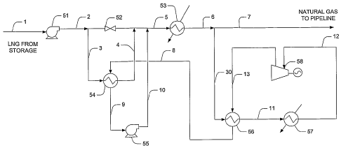
Figure 1 is one exemplary configuration of a power production scheme coupled
to an
LNG regasification operation according to the inventive subject matter.
Figure 2 is another exemplary configuration of a power production scheme
coupled to
an LNG regasification operation according to the inventive subject matter.
Detailed Description
The inventor has discovered that refrigeration content in LNG can be
advantageously
employed in the production of power in a regasification facility by using at
least a portion of
the regasified LNG as a working fluid in an open cycle, wherein the LNG is
condensed after
expansion using the cryogenic refrigeration content of the LNG fed to the
facility. Depending
on the vaporizer configuration, an intermediate heat transfer medium may be
employed in
contemplated configurations.
It should be particularly appreciated that the LNG is pumped to a desired
pressure to
supply refrigeration in an open power cycle that uses LNG as the working
fluid. In such
4
CA 02615850 2008-01-17
WO 2007/011921 PCT/US2006/027798
plants, the LNG working fluid is condensed using the cryogenic temperatures of
the LNG
that is delivered to the plant. Therefore, it should be recognized that LNG
regasification
and/or power generation may be accomplished with the use of ambient air
vaporizers,
seawater vaporizers, and/or waste heat from gas turbine exhaust or fired
heaters, which
significantly reduces fuel consumption in power generation. Moreover, as LNG
is used as a
working fluid, no external working fluid is required. Viewed from a different
perspective, a
substantially increased amount of refrigeration content is recoverable as the
working fluid
will not freeze at cryogenic temperatures.
An exemplary open LNG power cycle is schematically depicted in Figure 1, in
which
power generation is operationally coupled to an LNG regasification plant
having a send out
rate of about 350 MMscfd. However, it should be noted that the inventive
subject matter is
not limited to a particular send out rate, and suitable plants may have higher
or lower rates.
Table 1 below shows a typical LNG composition LNG in Figure 1.
COMPONENT MOL%
CI 86 to 95%
C2 4 to 14%
C3-C5 3 to 7%
C6+ 0.5 to 1%
N2+C02 0.1 to 1%
Table 1
LNG stream 1 from LNG storage tank or other sources is typically at a pressure
between 70 psig to 100 psig and at a temperature of about -260 F to -250 F.
Stream 1 is
pumped by LNG pump 51 to a suitable pressure, typically about 1200 to 1600
psig to form
pressurized LNG stream 2, as needed to meet pipeline requirement. As used
herein, the terin
"about" in conjunction with a numeral refers to a range of that numeral
starting from 20%
below the numeral to 20% above the numeral, inclusive. For example, the term
"about
-150 F" refers to a range of -180 F to -120 F, and the term "about 1400 psig"
refers to a
range of 1372 psig to 1680 psig.
A portion of the LNG stream 2 is split off as stream 3 and sent to exchanger
54 using
bypass valve 52. Stream 3 is heated in the exchanger from about -250 F to
about -170 F to
form stream 4, while the expanded vaporized natural gas working fluid 8 is
cooled and
condensed from about 40 F to about -215 F. The so condensed LNG working fluid
9 is at a
pressure of about 80 psig and a temperature of about -215 F and pumped by pump
55 to a
5
CA 02615850 2008-01-17
WO 2007/011921 PCT/US2006/027798
pressure of about 1400 psig, forming stream 10 that is combined with the
remaining portion
of the LNG stream 2 to form combined stream 5. Stream 5 is then heated in
vaporizer 53 to
about 40 F with heat supplied by ambient heat sources (e.g., ambient air or
seawater). The
vaporized natural gas stream 6 is then split into a first portion (about 85%,
stream 7) and a
second portion (about 15%, stream 30) using a flow control device (not shown).
It should be
noted that, among other factors, the split ratio of the vaporized natural gas
stream generally
depends on the LNG composition and the desirable power generation output.
Stream 7 is sent
to the consumer pipeline, while stream 30 is utilized in the power cycle as
described below.
Stream 30 is first heated in exchanger 56 to about 155 F forming stream 11
using the
heat content from the expander discharge stream 13. The so heated vaporized
natural gas is
further heated in heater 57 with an external source to about 450 F (or higher)
forming stream
12. It should be appreciated that numerous external heat sources are suitable
(e.g., flue gas
from a gas turbine, waste heat recovery unit, and/or a fired heater). The
resultant high
pressure high temperature working fluid stream 12 is then expanded in expander
58 to about
75 psig forming stream 13, generating power that can be used to drive an
electric generator.
Heat content in the expander discharge is recovered in exchanger 56 forming
stream 8 that is
subsequently condensed in exchanger 54 forming stream 9 to repeat the power
cycle.
In the exemplary configuration of Figure 1, the open power cycle circulates
about 550
GPM LNG working fluid, generating about 5,000 kW. The power generation
efficiency, as
calculated by the heat equivalent of net power output from the cycle divided
by heat input to
exchanger 57, is about 68%. The efficiency can be further increased with
higher operating
temperature and pressure, which should be balanced with higher equipment costs
and heating
requirement. With respect to the quantities of streams 3 and 30 that are drawn
from LNG
streams 2 and 6, respectively, it should be recognized that the particular
amounts will be at
least in part determined by the amount of power that is to be generated. For
example, where
relatively large quantities of power are desired, stream 30 may be more than
15% (e.g., 16-
20%, 20-25%, or even higher) of stream 6. Consequently, and depending on the
temperature
of cooled expander discharge 8, amounts of stream 3 may vary considerably.
Most typically,
stream 3 will be at least in an amount effective to condense expanded natural
gas stream 8.
Thus, it should be recognized that a first portion of the cryogenic
refrigeration content of the
LNG stream 2 is used as a heat sink for the LNG working fluid, and that at
least a portion of
6
CA 02615850 2008-01-17
WO 2007/011921 PCT/US2006/027798
the LNG in at least partially vaporized form is heated and expanded to produce
work in an
open power cycle.
Another exemplary open LNG power cycle is schematically depicted in Figure 2,
in
which power generation is operationally coupled to an LNG regasification plant
that uses an
intermediary heat transfer fluid (e.g., glycol-water, alcohol, or Dowtherm,
etc.) to provide
heat to the LNG vaporizer. Here, the intermediate fluid stream 14 is pumped by
pump 59 to
about 120 psig forming stream 15 which is preferably heated with ambient air
in vaporizer 60
forming stream 16. A first portion of stream 16 is fiuther heated via stream
17 with waste
heat 22 in exchanger 61 to about 480 F or higher, forming a heated stream 19
that heats the
preheated LNG stream 11. Stream 19 exits heat exchanger 57 as stream 20 and is
coinbined
with the second portion of stream 16 (streain 18) to form stream 21 that is
used in vaporizer
53. With respect to remaining components of Figure 2, the same considerations
apply for
like components with like numerals as depicted in Figure 1.
Suitable heat sources for exchangers 22 and 57 include gas turbine combustion
air,
cooling water to surface condensers, flue gas from a gas turbine, and/or flue
gas from a fuel
fired heater. However, numerous alternative heat sources are also
contemplated, including
units found in plants other than a combined cycle plant. Similarly, suitable
recipients for
LNG cold may also include numerous cryogenic processes (e.g., air separation
plants) in
which LNG cools the air or other gas, processes providing flue gas (e.g.,
reformer flue gases,
etc.), and other processes acting as a cold sink (e.g., carbon dioxide liquids
production plants,
desalination plants, or food freezing facilities). Therefore, it should be
appreciated that LNG
drawn from a location upstrea.in of a vaporizer can be used to condense
expanded vaporized
natural gas working fluid from a preferably open power cycle wherein the
vaporized natural
gas working fluid is drawn from a location downstream of the vaporizer.
In further contemplated aspect of the inventive subject matter, it is
generally preferred
that power production is operationally coupled with LNG regasification
facilities and/or LNG
receiving terminals, and particularly preferred configurations include those
in which LNG is
regasified in a process in which at least part of the LNG is used to generate
electric power
(most preferably with integration to a combined power cycle). For example,
suitable plants
and methods are described in our commonly owned and co-pending international
patent
application with the serial numbers PCT/US03/25372 and PCT/US03/26805, which
are
incorporated by reference herein.
7
CA 02615850 2008-01-17
WO 2007/011921 PCT/US2006/027798
Consequently, and depending on the particular heat source, it should be
recognized
that the energy needed for regasification of the LNG may be entirely, or only
partially
provided by contemplated heat sources. Where the heat source provides
insufficient
quantities of heat to completely gasify the LNG, it should be recognized that
supplemental
heat may be provided. Suitable supplemental heat sources include waste heat
from the steam
turbine discharge, condensation duty from the flue gas, ambient heating with
air (e.g., by
providing air conditioning to buildings), with seawater, or fuel gas.
Consequently, it should
be appreciated that contemplated configuration and processes may be used to
retrofit existing
regasification plants to iniprove power generation efficiencies and
flexibility, or may be used
in new installations.
It should be especially appreciated that numerous advantages may be achieved
using
configurations according to the inventive subject matter. Among other things,
contemplated
configurations provide highly efficient LNG power generation cycles without
external
working fluid, such as steam, or hydrocarbons with a composition other than
LNG.
Contemplated processes can be coupled with any type of power plant and still
provide benefit
or improved efficiency. Especially preferred configurations utilize the LNG
cold in the
cryogenic region and LNG as the working fluid to achieve high thermal
efficiency, typically
in the range of about 70% or higher. In most preferred plants, the LNG send
out is pumped to
supercritical pressure and regasified using conventional vaporizers while a
portion of the
regasified product is split off as the LNG working fluid (vaporized natural
gas) to the open
power cycle. The LNG working fluid is further superheated and expanded to a
lower pressure
to thereby generate power, wherein the expanded working fluid is condensed
utilizing
cryogenic temperatures of the LNG send out in the -250 F to -150 F range.
Alternatively, the
LNG working fluid is pumped to a supercritical pressure (here: above
cricondenbar pressure),
and heated with an external heat source, and then expanded to a lower pressure
for power
generation with a heat source integral with or thermally coupled to the power
cycle. The
expanded working fluid is condensed using the LNG send out, pumped and mixed
with the
send out LNG and heated in the vaporizers. Based on the conceptually simple
configuration
of contemplated plants, it should be recognized that the power generation
according to the
inventive subject matter may be implemented as a retrofit to an existing
facility or in a
facility built from scratch.
8
CA 02615850 2008-01-17
WO 2007/011921 PCT/US2006/027798
Thus, specific embodiments and applications for configurations and methods for
power generation with integrated LNG regasification have been disclosed. It
should be
apparent, however, to those slcilled in the art that many more modifications
besides those
already described are possible without departing from the inventive concepts
herein. The
inventive subject matter, therefore, is not to be restricted except in the
spirit of the present
disclosure. Moreover, in interpreting the specification, all terms should be
interpreted in the
broadest possible manner consistent with the context. In particular, the terms
"comprises"
and "comprising" should be interpreted as referring to elements, components,
or steps in a
non-exclusive manner, indicating that the referenced elements, components, or
steps may be
present, or utilized, or combined with other elements, components, or steps
that are not
expressly referenced. Furthermore, where a definition or use of a term in a
reference, which is
incorporated by reference herein is inconsistent or contrary to the definition
of that term
provided herein, the definition of that term provided herein applies and the
definition of that
term in the reference does not apply.
9