Note: Descriptions are shown in the official language in which they were submitted.
CA 02616066 2008-01-21
WO 2007/016761 PCT/CA2006/001224
1
TITLE OF THE INVENTION
Electric machine provided with an internal stator
FIELD OF THE INVENTION
[0001] The present invention relates to electric machines. More
specifically, the present invention is concerned with an internal stator
electric
machine provided with a securing arrangement to mount the internal stator to
the casing of the machine.
BACKGROUND OF THE INVENTION
[0002] Electric machines are well known in the art. They usually are
provided with a fixed stator and a rotating rotor. Generally, the stator is
external and the rotor is rotatably mounted inside the stator, coaxially
therewith.
[0003] In some electric machines, the stator is internal and the
cylindrical rotor is coaxially mounted outside the stator. These machines will
be
referred herein as internal stator electric machines.
[0004] To mount the stator of such an internal stator electric
machine to the casing of the machine, conventional fasteners passing through
openings in the laminations of the stator are often used. However, since heat
is mainly generated in the internal stator, dilatation may induce undesirable
stress on these fasteners and on other elements of the electric machine.
Furthermore, the use of conventional fasteners for this task implies that the
casing of the machine is so designed as to include a wall adjacent to the
stator
to allow the fastener therein, which limits the design of the machine's
casing.
CA 02616066 2008-01-21
WO 2007/016761 PCT/CA2006/001224
2
OBJECTS OF THE INVENTION
[0005] An object of the present invention is therefore to provide an
improved internal stator electric machine.
SUMMARY OF THE INVENTION
[0006] More specifically, in accordance with the present invention,
there is provided an electric machine comprising:
a casing provided with a generally cylindrical inner wall and
defining a rotation axis;
a generally cylindrical cooling assembly mounted to the
generally cylindrical inner wall; a first rotation preventing arrangement
being
provided between the inner wall and the cooling assembly to prevent rotation
therebetween;
a stator mounted to the cooling assembly;
a longitudinal movement preventing assembly mounted to
both the casing and at least one of the cooling assembly and the stator to
prevent longitudinal movements therebetween; and
a rotor so mounted to the casing as to be rotatable about the
rotation axis.
[0007] Other objects, advantages and features of the present
invention will become more apparent upon reading of the following non-
restrictive description of preferred embodiments thereof, given by way of
example only with reference to the accompanying drawings.
CA 02616066 2008-01-21
WO 2007/016761 PCT/CA2006/001224
3
BRIEF DESCRIPTION OF THE DRAWINGS
[0008] In the appended drawings:
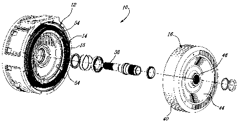
[0009] Figure 1 is an exploded perspective view of an electric
machine provided with a securing arrangement to mount the internal stator to
the casing of the machine according to an embodiment of the present
invention;
[0010] Figure 2 is a front elevation of the stator of the electric
machine of Figure 1 mounted to the casing of the machine, the rotor being
absent from this figure for clarity purpose;
[0011] Figure 3 is a side sectional view taken along line 3-3 of Figure
2; and
[0012] Figure 4 is a side sectional view taken along line 4-4 of Figure
2.
DETAILED DESCRIPTION
[0013] Generally stated, the present invention proposes to provide
an electric machine provided with an internal stator provided with a central
opening configured to receive a generally cylindrical cooling assembly
therein.
The stator assembly is secured to the cooling assembly. The cylindrical
cooling assembly is mounted to the casing of the electric machine and a
rotation preventing arrangement, for example in the form of a key and keyway
arrangement, is used to prevent rotation therebetween.
CA 02616066 2008-01-21
WO 2007/016761 PCT/CA2006/001224
4
[0014] Turning now to the appended figures, an electric machine 10
will be described. The electric machine 10 includes a casing 12, a stator 14,
a
cooling assembly 15 and a rotor 16.
[0015] As can be better seen from Figure 3, the integral casing 12
includes an external wall 18, an internal wall 20 and a central opening 22.
The
internal wall 20 is connected to the external wall 18 via a first intermediate
wall
24 and the central opening 22 is done in a second intermediate wall 26
integral
with the internal wall 20. The central opening 22 defining a machine rotation
axis 23.
[0016] The stator 14 includes a plurality of laminations (not shown)
that are conventionally stacked to yield a stator having the desired length
along
the rotation axis 23. These laminations are conventionally provided with slots
28 allowing stator coils 30 to be inserted therein. Wedges 32 are provided to
maintain the coils 30 in the slots 28.
[0017] One skilled in the art will easily understand that other stator
configurations are possible.
[0018] The cooling assembly 15 in interposed between the internal
wall 20 and the stator 14 as will be described hereinbelow. The function of
the
cooling assembly 15 is to remove the heat generated by the stator 14 from the
electric machine 10. A more detailed description of a cooling assembly that
could be used as the cooling assembly 15 may be found in US patent
6,819,016 issued on November 16, 2004 and entitled "Liquid cooling
arrangement for electric machines". This document is incorporated herein by
reference.
CA 02616066 2008-01-21
WO 2007/016761 PCT/CA2006/001224
[0019] As can be better seen from Figure 2, the cooling assembly 15
includes a gap 34 provided with a biasing assembly 36 that forces the external
surface of the cooling assembly 15 against the internal surface of the stator
14
to yield an adequate heat transfer between these two elements. The appended
figures illustrate a biasing assembly 36 including three compression springs
37
mounted in the gap 34. Of course, other types of biasing assemblies could be
used. For example, some of the biasing assemblies described in United States
patent application number 10/726,397 filed on December 2"d 2003 and entitled
"Cooling device including a biasing element" could be used herein as the
biasing assembly 36. This document is incorporated herein by reference.
[0020] The rotor 16 is so configured and sized as to be mounted to
the electric machine 10 via a central shaft 38 that is rotatably received in
the
central opening 22 to allow rotation of the rotor 16 about the machine
rotation
axis 23. The rotor is generally bowl shaped and includes a peripheral wall 40
having an internal surface onto which permanent magnets 42 are mounted. A
shaped wall 44 provided with a central aperture 46 is integral with the
peripheral wall 40.
[0021] Returning to Figure 2 of the appended drawings, a securing
arrangement used to mount the stator to the casing 12 of the electric machine
will be described.
[0022] To secure the cooling assembly 15 to the internal wall 20 of
the casing 12, a first key and keyway arrangement 48 is provided. More
specifically, a first keyway is provided on the outer surface the external
wall 20
and a second keyway is provided on the inner surface of the cooling assembly
15. A suitably sized key 52 (see Figure 3) is inserted in these two keyways
when they are placed in register. Rotation of the cooling assembly 15 with
respect to the internal wall 20 is therefore prevented.
CA 02616066 2008-01-21
WO 2007/016761 PCT/CA2006/001224
6
[0023] As mentioned hereinabove, the cooling assembly 15 is
mounted to the stator 14 via the biasing assembly 36. More specifically, the
external surface of the cooling assembly 15 is biased against the internal
surface of the stator 14 by the biasing assembly 36.
[0024] To prevent rotation of the stator 14 with respect to the cooling
assembly 15, a second key and keyway arrangement 50 is provided. More
specifically, a first keyway is provided on the outer surface of the cooling
assembly 15 and a key is integral with the inner surface of the laminations of
the stator 14. Of course, alternatively, the inner surface of the laminations
of
the stator 14 could be provided with a keyway (not shown) and a separate key
(not shown) could be used to interconnect the keyways.
[0025] To prevent longitudinal movements of the cooling
assembly/stator with respect to the internal wall 20, a longitudinal movement
preventing assembly including, for example, five brackets 54 is provided, as
can be seen from Figure 2. Each of the five brackets 54 is mounted to the
exposed axial end of the internal wall 20 via a fastener 56.
[0026] More specifically, as can be better seen from Figure 4, the
fastener 56 is threaded in a threaded aperture 58 of the exposed axial end 61
of the wall 20. The bracket 54 includes a main portion 60 and two legs 62 and
64. Leg 62 is so designed as to hook the wall 20 while the leg 64 is designed
to apply pressure onto the stator 14. Longitudinal movements of the cooling
assembly/stator with respect to the internal wall 20 are therefore prevented.
[0027] Returning to Figure 3, the corner 55 of one of the keyway of
the intermediate wall 20 is such that longitudinal movement of the cooling
assembly/stator away from the brackets 54 is prevented.
CA 02616066 2008-01-21
WO 2007/016761 PCT/CA2006/001224
7
[0028] The longitudinal movement of the cooling assembly/stator is
therefore prevented without having to mechanically fasten the stator directly
to
the casing. The brackets 54, since they are not fastened to the cooling
assembly/stator allow the potential expansion of the stator 14 caused by heat.
Furthermore, no fastening apertures are required in the laminations, which may
increase the power density of the electric machine 10.
[0029] The use of the key and keyway arrangements also allows the
cooling assembly to follow the expansion and contraction of the stator without
radial restriction, therefore minimizing potential loss of contact between the
cooling assembly and the stator.
[0030] One skilled in the art will easily understand that the number,
shape and position of brackets can be modified depending on the configuration
of the electric machine and/or other requirements. Furthermore, other means
could be provided to prevent movements between the cooling assembly/stator
with respect to the casing. Similarly, more that one first and/or second key
and
keyway arrangement could be used.
[0031] It is also to be noted that the key and keyway arrangement 50
could be omitted should the biasing assembly 36, or its equivalent, be secure
enough to prevent rotation between the stator 14 and the cooling assembly 15.
[0032] It is also to be noted that other elements are necessary for
the adequate operation of the electric machine 10. However, these elements
have not been shown and/or described herein since they are not believed
relevant to the present invention.
CA 02616066 2008-01-21
WO 2007/016761 PCT/CA2006/001224
8
[0033] Although the present invention has been described
hereinabove by way of preferred embodiments thereof, it can be modified,
without departing from the spirit and nature of the subject invention as
defined
in the appended claims.