Sélection de la langue

Search

Sommaire du brevet 2616066 

Énoncé de désistement de responsabilité concernant l'information provenant de tiers

Une partie des informations de ce site Web a été fournie par des sources externes. Le gouvernement du Canada n'assume aucune responsabilité concernant la précision, l'actualité ou la fiabilité des informations fournies par les sources externes. Les utilisateurs qui désirent employer cette information devraient consulter directement la source des informations. Le contenu fourni par les sources externes n'est pas assujetti aux exigences sur les langues officielles, la protection des renseignements personnels et l'accessibilité.

Disponibilité de l'Abrégé et des Revendications

L'apparition de différences dans le texte et l'image des Revendications et de l'Abrégé dépend du moment auquel le document est publié. Les textes des Revendications et de l'Abrégé sont affichés :

  • lorsque la demande peut être examinée par le public;
  • lorsque le brevet est émis (délivrance).
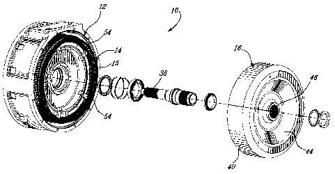
(12) Demande de brevet: (11) CA 2616066
(54) Titre français: MACHINE ELECTRIQUE POURVUE D'UN STATOR INTERNE
(54) Titre anglais: ELECTRIC MACHINE PROVIDED WITH AN INTERNAL STATOR
Statut: Réputée abandonnée et au-delà du délai pour le rétablissement - en attente de la réponse à l’avis de communication rejetée
Données bibliographiques
(51) Classification internationale des brevets (CIB):
  • H02K 1/06 (2006.01)
  • H02K 9/00 (2006.01)
  • H05K 5/00 (2006.01)
(72) Inventeurs :
  • ROUNDELL, JANE (Canada)
(73) Titulaires :
  • TM4 INC.
(71) Demandeurs :
  • TM4 INC. (Canada)
(74) Agent: SMART & BIGGAR LP
(74) Co-agent:
(45) Délivré:
(86) Date de dépôt PCT: 2006-07-25
(87) Mise à la disponibilité du public: 2007-02-15
Requête d'examen: 2009-07-20
Licence disponible: S.O.
Cédé au domaine public: S.O.
(25) Langue des documents déposés: Anglais

Traité de coopération en matière de brevets (PCT): Oui
(86) Numéro de la demande PCT: PCT/CA2006/001224
(87) Numéro de publication internationale PCT: WO 2007016761
(85) Entrée nationale: 2008-01-21

(30) Données de priorité de la demande:
Numéro de la demande Pays / territoire Date
60/706,781 (Etats-Unis d'Amérique) 2005-08-10

Abrégés

Abrégé français

La présente invention se rapporte à une machine électrique qui inclue un stator interne pourvu d~une ouverture centrale. Un ensemble de refroidissement généralement cylindrique est monté à l~intérieur de l~ouverture centrale via une première clavette et une rainure de clavette. L~ensemble de refroidissement cylindrique est monté sur le boîtier de la machine électrique via une deuxième clavette et une rainure de clavette.


Abrégé anglais


An electric machine is described herein. The machine includes an internal
stator provided with a central opening. A generally cylindrical cooling
assembly is mounted inside the central opening via a first key and keyway
arrangement. The cylindrical cooling assembly is mounted to the casing of the
electric machine via a second key and keyway arrangement.

Revendications

Note : Les revendications sont présentées dans la langue officielle dans laquelle elles ont été soumises.


9
WHAT IS CLAIMED IS:
1. ~An electric machine comprising:
a casing provided with a generally cylindrical inner wall and
defining a rotation axis;
a generally cylindrical cooling assembly mounted to the
generally cylindrical inner wall; a first rotation preventing arrangement
being
provided between the inner wall and the cooling assembly to prevent rotation
therebetween;
a stator mounted to the cooling assembly;
a longitudinal movement preventing assembly mounted to
both the casing and at least one of the cooling assembly and the stator to
prevent longitudinal movements therebetween; and
a rotor so mounted to the casing as to be rotatable about the
rotation axis.
2. ~An electric machine as recited in claim 1, wherein the first
rotation preventing arrangement includes a key and keyway arrangement
provided between the cooling assembly and the inner wall of the casing.
3. ~An electric machine as recited in claim 2, wherein the key
and keyway arrangement includes a first keyway provided in the cooling
assembly, a second keyway provided in the inner wall of the casing and a key
configured and sized as to enter the first and second keyways.
4. ~An electric machine as recited in claim 1, wherein the
generally cylindrical cooling assembly including an external surface and being
provided with a gap provided with a biasing assembly; the stator being
provided
with a generally cylindrical inner surface configured and sized as to be
mounted
to the external surface of the cooling assembly; the biasing assembly being so

mounted to the cooling assembly as to selectively force the external surface
of
the cooling assembly against the internal surface of the stator.
5. ~An electric machine as recited in claim 5, wherein the
biasing assembly includes three compression springs mounted in the gap of
the cooling assembly.
6. ~An electric machine as recited in claim 1, further
comprising a second rotation preventing arrangement being provided between
the cooling assembly and the stator to prevent rotation therebetween.
7. ~An electric machine as recited in claim 6, wherein the
second rotation preventing arrangement includes a key and keyway
arrangement provided between the cooling assembly and the stator.
8. ~An electric machine as recited in claim 7, wherein the key
and keyway arrangement includes a keyway provided in the cooling assembly
and a key integral with the stator; the key being configured and sized as to
enter the keyway.
9. ~An electric machine as recited in claim 1, wherein the
generally cylindrical inner wall is provided with an axial end and wherein the
longitudinal movement preventing assembly includes at least one bracket
mounted to the axial end of the inner wall, the at least one bracket
contacting at
least one of the cooling assembly and the stator to prevent longitudinal
movement therebetween.
10. ~An electric machine as recited in claim 9, wherein the
axial end of the generally cylindrical inner wall is provided with a threaded

11
aperture and wherein the bracket is mounted to the threaded aperture via a
fastener.
11. ~An electric machine as recited in claim 10, wherein the at
least one bracket includes a main portion and first and second legs; the main
portion including an aperture allowing the fastener therethrough; the first
leg
being so configured and sized as to hook the inner wall and the second leg
being so configured and sized as to apply pressure onto the stator.
12. ~An electric machine as recited in claim 9, wherein the at
least one bracket includes five brackets.

Description

Note : Les descriptions sont présentées dans la langue officielle dans laquelle elles ont été soumises.

CA 02616066 2008-01-21
WO 2007/016761 PCT/CA2006/001224
1
TITLE OF THE INVENTION
Electric machine provided with an internal stator
FIELD OF THE INVENTION
[0001] The present invention relates to electric machines. More
specifically, the present invention is concerned with an internal stator
electric
machine provided with a securing arrangement to mount the internal stator to
the casing of the machine.
BACKGROUND OF THE INVENTION
[0002] Electric machines are well known in the art. They usually are
provided with a fixed stator and a rotating rotor. Generally, the stator is
external and the rotor is rotatably mounted inside the stator, coaxially
therewith.
[0003] In some electric machines, the stator is internal and the
cylindrical rotor is coaxially mounted outside the stator. These machines will
be
referred herein as internal stator electric machines.
[0004] To mount the stator of such an internal stator electric
machine to the casing of the machine, conventional fasteners passing through
openings in the laminations of the stator are often used. However, since heat
is mainly generated in the internal stator, dilatation may induce undesirable
stress on these fasteners and on other elements of the electric machine.
Furthermore, the use of conventional fasteners for this task implies that the
casing of the machine is so designed as to include a wall adjacent to the
stator
to allow the fastener therein, which limits the design of the machine's
casing.

CA 02616066 2008-01-21
WO 2007/016761 PCT/CA2006/001224
2
OBJECTS OF THE INVENTION
[0005] An object of the present invention is therefore to provide an
improved internal stator electric machine.
SUMMARY OF THE INVENTION
[0006] More specifically, in accordance with the present invention,
there is provided an electric machine comprising:
a casing provided with a generally cylindrical inner wall and
defining a rotation axis;
a generally cylindrical cooling assembly mounted to the
generally cylindrical inner wall; a first rotation preventing arrangement
being
provided between the inner wall and the cooling assembly to prevent rotation
therebetween;
a stator mounted to the cooling assembly;
a longitudinal movement preventing assembly mounted to
both the casing and at least one of the cooling assembly and the stator to
prevent longitudinal movements therebetween; and
a rotor so mounted to the casing as to be rotatable about the
rotation axis.
[0007] Other objects, advantages and features of the present
invention will become more apparent upon reading of the following non-
restrictive description of preferred embodiments thereof, given by way of
example only with reference to the accompanying drawings.

CA 02616066 2008-01-21
WO 2007/016761 PCT/CA2006/001224
3
BRIEF DESCRIPTION OF THE DRAWINGS
[0008] In the appended drawings:
[0009] Figure 1 is an exploded perspective view of an electric
machine provided with a securing arrangement to mount the internal stator to
the casing of the machine according to an embodiment of the present
invention;
[0010] Figure 2 is a front elevation of the stator of the electric
machine of Figure 1 mounted to the casing of the machine, the rotor being
absent from this figure for clarity purpose;
[0011] Figure 3 is a side sectional view taken along line 3-3 of Figure
2; and
[0012] Figure 4 is a side sectional view taken along line 4-4 of Figure
2.
DETAILED DESCRIPTION
[0013] Generally stated, the present invention proposes to provide
an electric machine provided with an internal stator provided with a central
opening configured to receive a generally cylindrical cooling assembly
therein.
The stator assembly is secured to the cooling assembly. The cylindrical
cooling assembly is mounted to the casing of the electric machine and a
rotation preventing arrangement, for example in the form of a key and keyway
arrangement, is used to prevent rotation therebetween.

CA 02616066 2008-01-21
WO 2007/016761 PCT/CA2006/001224
4
[0014] Turning now to the appended figures, an electric machine 10
will be described. The electric machine 10 includes a casing 12, a stator 14,
a
cooling assembly 15 and a rotor 16.
[0015] As can be better seen from Figure 3, the integral casing 12
includes an external wall 18, an internal wall 20 and a central opening 22.
The
internal wall 20 is connected to the external wall 18 via a first intermediate
wall
24 and the central opening 22 is done in a second intermediate wall 26
integral
with the internal wall 20. The central opening 22 defining a machine rotation
axis 23.
[0016] The stator 14 includes a plurality of laminations (not shown)
that are conventionally stacked to yield a stator having the desired length
along
the rotation axis 23. These laminations are conventionally provided with slots
28 allowing stator coils 30 to be inserted therein. Wedges 32 are provided to
maintain the coils 30 in the slots 28.
[0017] One skilled in the art will easily understand that other stator
configurations are possible.
[0018] The cooling assembly 15 in interposed between the internal
wall 20 and the stator 14 as will be described hereinbelow. The function of
the
cooling assembly 15 is to remove the heat generated by the stator 14 from the
electric machine 10. A more detailed description of a cooling assembly that
could be used as the cooling assembly 15 may be found in US patent
6,819,016 issued on November 16, 2004 and entitled "Liquid cooling
arrangement for electric machines". This document is incorporated herein by
reference.

CA 02616066 2008-01-21
WO 2007/016761 PCT/CA2006/001224
[0019] As can be better seen from Figure 2, the cooling assembly 15
includes a gap 34 provided with a biasing assembly 36 that forces the external
surface of the cooling assembly 15 against the internal surface of the stator
14
to yield an adequate heat transfer between these two elements. The appended
figures illustrate a biasing assembly 36 including three compression springs
37
mounted in the gap 34. Of course, other types of biasing assemblies could be
used. For example, some of the biasing assemblies described in United States
patent application number 10/726,397 filed on December 2"d 2003 and entitled
"Cooling device including a biasing element" could be used herein as the
biasing assembly 36. This document is incorporated herein by reference.
[0020] The rotor 16 is so configured and sized as to be mounted to
the electric machine 10 via a central shaft 38 that is rotatably received in
the
central opening 22 to allow rotation of the rotor 16 about the machine
rotation
axis 23. The rotor is generally bowl shaped and includes a peripheral wall 40
having an internal surface onto which permanent magnets 42 are mounted. A
shaped wall 44 provided with a central aperture 46 is integral with the
peripheral wall 40.
[0021] Returning to Figure 2 of the appended drawings, a securing
arrangement used to mount the stator to the casing 12 of the electric machine
will be described.
[0022] To secure the cooling assembly 15 to the internal wall 20 of
the casing 12, a first key and keyway arrangement 48 is provided. More
specifically, a first keyway is provided on the outer surface the external
wall 20
and a second keyway is provided on the inner surface of the cooling assembly
15. A suitably sized key 52 (see Figure 3) is inserted in these two keyways
when they are placed in register. Rotation of the cooling assembly 15 with
respect to the internal wall 20 is therefore prevented.

CA 02616066 2008-01-21
WO 2007/016761 PCT/CA2006/001224
6
[0023] As mentioned hereinabove, the cooling assembly 15 is
mounted to the stator 14 via the biasing assembly 36. More specifically, the
external surface of the cooling assembly 15 is biased against the internal
surface of the stator 14 by the biasing assembly 36.
[0024] To prevent rotation of the stator 14 with respect to the cooling
assembly 15, a second key and keyway arrangement 50 is provided. More
specifically, a first keyway is provided on the outer surface of the cooling
assembly 15 and a key is integral with the inner surface of the laminations of
the stator 14. Of course, alternatively, the inner surface of the laminations
of
the stator 14 could be provided with a keyway (not shown) and a separate key
(not shown) could be used to interconnect the keyways.
[0025] To prevent longitudinal movements of the cooling
assembly/stator with respect to the internal wall 20, a longitudinal movement
preventing assembly including, for example, five brackets 54 is provided, as
can be seen from Figure 2. Each of the five brackets 54 is mounted to the
exposed axial end of the internal wall 20 via a fastener 56.
[0026] More specifically, as can be better seen from Figure 4, the
fastener 56 is threaded in a threaded aperture 58 of the exposed axial end 61
of the wall 20. The bracket 54 includes a main portion 60 and two legs 62 and
64. Leg 62 is so designed as to hook the wall 20 while the leg 64 is designed
to apply pressure onto the stator 14. Longitudinal movements of the cooling
assembly/stator with respect to the internal wall 20 are therefore prevented.
[0027] Returning to Figure 3, the corner 55 of one of the keyway of
the intermediate wall 20 is such that longitudinal movement of the cooling
assembly/stator away from the brackets 54 is prevented.

CA 02616066 2008-01-21
WO 2007/016761 PCT/CA2006/001224
7
[0028] The longitudinal movement of the cooling assembly/stator is
therefore prevented without having to mechanically fasten the stator directly
to
the casing. The brackets 54, since they are not fastened to the cooling
assembly/stator allow the potential expansion of the stator 14 caused by heat.
Furthermore, no fastening apertures are required in the laminations, which may
increase the power density of the electric machine 10.
[0029] The use of the key and keyway arrangements also allows the
cooling assembly to follow the expansion and contraction of the stator without
radial restriction, therefore minimizing potential loss of contact between the
cooling assembly and the stator.
[0030] One skilled in the art will easily understand that the number,
shape and position of brackets can be modified depending on the configuration
of the electric machine and/or other requirements. Furthermore, other means
could be provided to prevent movements between the cooling assembly/stator
with respect to the casing. Similarly, more that one first and/or second key
and
keyway arrangement could be used.
[0031] It is also to be noted that the key and keyway arrangement 50
could be omitted should the biasing assembly 36, or its equivalent, be secure
enough to prevent rotation between the stator 14 and the cooling assembly 15.
[0032] It is also to be noted that other elements are necessary for
the adequate operation of the electric machine 10. However, these elements
have not been shown and/or described herein since they are not believed
relevant to the present invention.

CA 02616066 2008-01-21
WO 2007/016761 PCT/CA2006/001224
8
[0033] Although the present invention has been described
hereinabove by way of preferred embodiments thereof, it can be modified,
without departing from the spirit and nature of the subject invention as
defined
in the appended claims.

Dessin représentatif
Une figure unique qui représente un dessin illustrant l'invention.
États administratifs

2024-08-01 : Dans le cadre de la transition vers les Brevets de nouvelle génération (BNG), la base de données sur les brevets canadiens (BDBC) contient désormais un Historique d'événement plus détaillé, qui reproduit le Journal des événements de notre nouvelle solution interne.

Veuillez noter que les événements débutant par « Inactive : » se réfèrent à des événements qui ne sont plus utilisés dans notre nouvelle solution interne.

Pour une meilleure compréhension de l'état de la demande ou brevet qui figure sur cette page, la rubrique Mise en garde , et les descriptions de Brevet , Historique d'événement , Taxes périodiques et Historique des paiements devraient être consultées.

Historique d'événement

Description Date
Exigences relatives à la nomination d'un agent - jugée conforme 2018-10-25
Exigences relatives à la révocation de la nomination d'un agent - jugée conforme 2018-10-25
Le délai pour l'annulation est expiré 2011-07-25
Demande non rétablie avant l'échéance 2011-07-25
Réputée abandonnée - omission de répondre à un avis sur les taxes pour le maintien en état 2010-07-26
Inactive : Demande ad hoc documentée 2009-08-28
Lettre envoyée 2009-08-27
Lettre envoyée 2009-08-20
Toutes les exigences pour l'examen - jugée conforme 2009-07-20
Requête d'examen reçue 2009-07-20
Exigences pour une requête d'examen - jugée conforme 2009-07-20
Inactive : Page couverture publiée 2008-04-16
Lettre envoyée 2008-04-14
Inactive : Notice - Entrée phase nat. - Pas de RE 2008-04-14
Inactive : Inventeur supprimé 2008-04-14
Inactive : CIB en 1re position 2008-02-12
Demande reçue - PCT 2008-02-11
Exigences pour l'entrée dans la phase nationale - jugée conforme 2008-01-21
Demande publiée (accessible au public) 2007-02-15

Historique d'abandonnement

Date d'abandonnement Raison Date de rétablissement
2010-07-26

Taxes périodiques

Le dernier paiement a été reçu le 2009-07-20

Avis : Si le paiement en totalité n'a pas été reçu au plus tard à la date indiquée, une taxe supplémentaire peut être imposée, soit une des taxes suivantes :

  • taxe de rétablissement ;
  • taxe pour paiement en souffrance ; ou
  • taxe additionnelle pour le renversement d'une péremption réputée.

Les taxes sur les brevets sont ajustées au 1er janvier de chaque année. Les montants ci-dessus sont les montants actuels s'ils sont reçus au plus tard le 31 décembre de l'année en cours.
Veuillez vous référer à la page web des taxes sur les brevets de l'OPIC pour voir tous les montants actuels des taxes.

Historique des taxes

Type de taxes Anniversaire Échéance Date payée
Taxe nationale de base - générale 2008-01-21
Enregistrement d'un document 2008-01-21
TM (demande, 2e anniv.) - générale 02 2008-07-25 2008-06-11
TM (demande, 3e anniv.) - générale 03 2009-07-27 2009-07-20
Requête d'examen (RRI d'OPIC) - générale 2009-07-20
Titulaires au dossier

Les titulaires actuels et antérieures au dossier sont affichés en ordre alphabétique.

Titulaires actuels au dossier
TM4 INC.
Titulaires antérieures au dossier
JANE ROUNDELL
Les propriétaires antérieurs qui ne figurent pas dans la liste des « Propriétaires au dossier » apparaîtront dans d'autres documents au dossier.
Documents

Pour visionner les fichiers sélectionnés, entrer le code reCAPTCHA :


Pour visualiser une image, cliquer sur un lien dans la colonne description du document. Pour télécharger l'image (les images), cliquer l'une ou plusieurs cases à cocher dans la première colonne et ensuite cliquer sur le bouton "Télécharger sélection en format PDF (archive Zip)" ou le bouton "Télécharger sélection (en un fichier PDF fusionné)".

Liste des documents de brevet publiés et non publiés sur la BDBC .

Si vous avez des difficultés à accéder au contenu, veuillez communiquer avec le Centre de services à la clientèle au 1-866-997-1936, ou envoyer un courriel au Centre de service à la clientèle de l'OPIC.


Description du
Document 
Date
(aaaa-mm-jj) 
Nombre de pages   Taille de l'image (Ko) 
Dessins 2008-01-20 4 149
Description 2008-01-20 8 263
Abrégé 2008-01-20 2 72
Revendications 2008-01-20 3 86
Dessin représentatif 2008-04-14 1 24
Rappel de taxe de maintien due 2008-04-13 1 113
Avis d'entree dans la phase nationale 2008-04-13 1 195
Courtoisie - Certificat d'enregistrement (document(s) connexe(s)) 2008-04-13 1 105
Accusé de réception de la requête d'examen 2009-08-19 1 188
Courtoisie - Lettre d'abandon (taxe de maintien en état) 2010-09-19 1 172
PCT 2008-01-20 2 59
Taxes 2008-06-10 1 30
Taxes 2009-07-19 1 29