Note: Descriptions are shown in the official language in which they were submitted.
CA 02616429 2007-12-27
2206.75024 PATENT APPLICATION
HAIR TRIMMER WITH ROTATABLE
DETENTED HEAD
BACKGROUND OF THE INVENTION
The present invention generally relates to an electric hair cutting
device such as a trimmer or a hair clipper. More particularly, the present
invention
relates to an electric hair cutting device having a detachable and rotatable
blade
assembly.
Electric hair trimmers or clippers are commonly used by stylists,
barbers, or individuals for styling hair, and typically include a handle
having
housing for enclosing a motor and a blade assembly associated with the handle.
The blade assembly is generally fixed to the handle at a certain orientation
for
receiving driving power from the motor. A bladeset in the blade assembly
includes a stationary blade and a moving blade reciprocating laterally and
substantially parallel relative to the stationary blade to provide a scissors-
type
cutting action.
One problem incurred when using current hair trimmers is orienting
the trimmer to reach areas that are difficult to cut, such as behind the ears
or the
nape of the neck. In these situations, the entire trimmer must generally be
maneuvered to change the orientation of the blades and reach the area to be
cut.
Such movement is awkward, and often causes discomfort to the user's wrist or
1
CA 02616429 2007-12-27
hand after continued use, and also decreases the accuracy and/or efficiency of
the
trimmer because the blades may not be entirely in contact with the cutting
area.
To attempt to resolve this problem, hair trimmers were developed
having heads rotatable relative to the handle, such as commonly owned U.S.
Pat.
No. 5,970,616 to Wahl et al., which discloses a hair trimmer having a lighted
rotating head. In Wahl, a cutting surface extends at an angle from a blade
housing
that is rotatable with respect to a main body of the hair trimmer. An
interface
plane is defined between the main body and the blade housing, and is arranged
at
an oblique angle relative to a longitudinal axis of the main body. Although
this
arrangement provides the user with added comfort, especially during beard
trimming alternately using both hands, due to the angle of the blade housing
relative to the longitudinal axis of the main body, it can still be difficult
to
efficiently reach and cut other hard to trim areas.
To address this problem, a hair trimmer with a rotatable and
pivotable blade assembly was developed, seen in commonly-owned U.S. Pat. Nos.
5,579,581 and 5,606,799 to Melton. In Melton, a handle portion is detachably
connected to a blade assembly by a ball-and-socket connection, allowing the
blade
assembly to be easily detached without the need for additional tools. The ball-
and-socket connection enables the blade assembly to rotate relative to the
handle
portion through 360 , as well as pivoting in a wide variety of positions,
enabling
the user to cut hard to reach areas. However, Melton does not provide a
mechanism that secures or locks the blade assembly in a desired position.
2
CA 02616429 2007-12-27
Accordingly, the blade assembly can move from the desired rotatable position
during use, causing inaccurate trimming.
Yet another design criterion of current hair trimmers with rotatable
blade assemblies is imbalance caused by operational vibrations. One source of
imbalance is the use of only one attachment or locking point holding the blade
assembly in position. Such imbalance reduces the cutting accuracy of the
trimmer,
and also causes user discomfort because of the resulting vibrations.
Accordingly, there is a need for an improved hair trimmer having a
blade assembly that is rotatable and detachable through 360 relative to the
handle,
and which addresses the above-listed design factors. Further, there is a need
for an
improved hair trimmer that provides a stable and balanced attachment between
the
blade assembly and handle, and reduces the vibrations experienced by the user
during operation.
BRIEF SUMMARY OF THE INVENTION
The present hair trimmer meets or exceeds all of the above-identified
needs. Specifically, the present hair trimmer includes a blade assembly that
can be
rotated 360 relative to the handle of the trimmer. The rotation is controlled
in
that a designated number of releasably locked operational positions are
available.
Further, in an alternate embodiment, the present hair trimmer
includes an actuation assembly having a memory function that allows the blade
assembly to be detached from the handle in one of the designated rotatable
3
CA 02616429 2011-05-12
positions and reattached in the same designated position. This feature allows
the
user to exchange blade assemblies for different types of trimming and
preserves
the selected bladeset orientation.
Also, the present hair trimmer provides a plurality of attachment
points between the blade assembly and the handle and is accordingly more
stable
and balanced than current hair trimmers, reducing the vibrations experienced
by
the user during operation.
More specifically, the present invention provides a hair trimmer
including a handle having a housing including an actuation assembly rotatable
relative to the housing, and a blade assembly including a reciprocating blade,
a
stationary blade and a blade assembly housing, the blade assembly constructed
and
arranged for being detachably engaged to the actuation assembly in a plane of
rotation of the actuation assembly.
In a broad aspect, the present invention relates to a hair trimmer
comprising: a handle having a housing including an actuation assembly
rotatable
relative to said housing to a plurality of releasably locked positions and
defining a
single plane of rotation; and a blade assembly including a reciprocating
blade, a
stationary blade and a blade assembly housing, said blade assembly housing
constructed and arranged for being independently detachably engaged to said
actuation assembly for common rotation of said actuation assembly, wherein
when
said blade assembly housing is engaged with said actuation assembly, said
blade
4
CA 02616429 2011-05-12
assembly is rotatable to a selected one of said plurality of releasably locked
positions.
In another broad aspect, the present invention relates to a hair
trimmer comprising: a handle having a housing including a motor and an
actuation
assembly rotatable relative to said housing to a plurality of releasably
locked
positions and having a casing with at least two detent assemblies equally
spaced
from each other and engaging a fixed socket plate; and a blade assembly
configured to be independently, detachably engaged to said actuation assembly
for
common rotation relative to said handle housing, said blade assembly including
a
reciprocating blade, a stationary blade and a blade assembly housing; said
rotation
of said blade assembly being defined by said plurality of releasably locked
positions represented by engagement of said blade assembly with said casing.
DESCRIPTION OF THE DRAWINGS
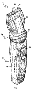
FIG. I is a front perspective view of a hair trimmer according to the
present invention;
FIG. IA is a top perspective view of an alternate embodiment of the
blade assembly of FIG. 1;
FIG. 2 is a fragmentary side view of the hair trimmer of FIG. 1
showing a blade assembly rotatable relative to a handle;
FIG. 3 is bottom view of the bladeset of the hair trimmer of FIG. 1;
4a
CA 02616429 2007-12-27
FIG. 4 is a top view of the actuation assembly of the hair trimmer;
FIG. 5 is a fragmentary cross-sectional side view of the hair trimmer
of FIG. 1 showing the attachment between the blade assembly and the handle;
FIG. 6 is an exploded fragmentary cross-sectional side view of FIG.
5 showing the blade assembly detached from the handle;
FIG. 7 is a cross-sectional view of the actuation assembly of the hair
trimmer;
FIG. 8 is a front perspective view of at least one detent assembly
engaging a socket plate of the hair trimmer according to the present hair
trimmer;
and
FIG. 9 is an exploded perspective view of an alternate embodiment
of the actuation assembly of the hair trimmer.
DETAILED DESCRIPTION OF THE INVENTION
Referring to FIGs. 1-4, a hair cutting device, referred to here as a
trimmer or clipper is generally designated 10, and includes a handle 12 having
a
housing 14. A feature of the present hair trimmer 10 is that the handle 12 is
configured for accommodating a variety of hair cutting blade assemblies. These
assemblies are designed for specific hair cutting tasks including, but not
limited to
shaving, general trimming, detail trimming and the like. A first blade
assembly 16
is a shaver including a reciprocating blade (not shown), a stationary blade 18
here
referenced to as a shaver foil, and a blade assembly housing 20. As known in
the
5
CA 02616429 2007-12-27
shaver art, the reciprocating blade moves transversely to the perforated foil
18 to
obtain efficient cutting action.
Referring now to FIG. IA, an alternate blade assembly is designated
16a and is designed for trimming. Shared or corresponding components with the
assembly 16 are designated with identical reference numbers. As is known in
the
art, a reciprocating toothed blade 22 moves parallel relative to a stationary
toothed
blade 18a to create a scissors-type cutting action.
Both of the blade assemblies 16, 16a include the blade housing 20
that is constructed and arranged to releasably engage an actuation assembly
24. In
the following discussion, when the assembly 16 is referred to, it will be
understood that assembly 16a is referred to as well. A feature of the present
trimmer 10 is that the actuation assembly 24 is rotatable relative to the
housing 14
as described in greater detail below.
The blade assembly 16 is constructed and arranged for being
detachably and rotatably engaged to the actuation assembly 24 in a plane of
rotation P of the actuation assembly. It is contemplated that this arrangement
is
advantageous over current hair trimmers, because when rotated in the plane of
rotation of the actuation assembly 24, the blade assembly 16 can more easily
access difficult to trim areas than conventional blade assemblies, and the
work
area is more visible. Rather than being freely rotatable, as is known in the
art, the
present blade assembly 16 is indexed to rotate to specific designated,
releasably
locked positions. Another contemplated advantage of this arrangement is that
it
6
CA 02616429 2007-12-27
improves increased maneuverability of the blade assembly 16, reducing the
stress
on the hand or wrist of the user compared to current hair trimmers.
The housings 20 are generally manufactured from a lightweight,
durable plastic, but it is appreciated that other materials with similar
properties
may be suitable, as known in the art.
Referring to now FIGs. 5 and 6, the handle 12 includes a least one
spring clip 26 configured for removably securing the blade assembly 16 to the
actuation assembly 24. Preferably, the spring clip 26 includes four elongate
spring
clip members 27 equally spaced and projecting normally from a generally
circular
ring 28 located within the actuation assembly 24. However, it is recognized
that
the spring clip 26 optionally includes an alternate number of spring clip
members
27, such as two or three members, varying to suit the application. Preferably
still,
the spring clip members 27 are integrally formed with the ring 28, although it
is
appreciated that other configurations may be suitable. Preferably, the spring
clip
members 27 are manufactured from a lightweight, resilient metal, but it is
appreciated that other materials with similar properties may be suitable. It
is also
recognized that the spring clip 26 and the spring clip members 27 are
optionally
integrally formed with the casing 32.
As shown in FIGs. 3-6, a generally octagonal frame 30 is provided
in the blade housing 20 and surrounds a complimentary casing 32 on the
actuation
assembly 24 upon releasable attachment of the blade assembly 16 and the
actuation assembly 24. However, it is appreciated that the frame 30 can be
other
7
CA 02616429 2007-12-27
shapes, depending on the application. The frame 30 is preferably manufactured
from a lightweight, durable plastic, but it is appreciated that other
materials with
similar properties may be suitable. The frame 30 defines at least one and
preferably a plurality of generally linear segments or channels 34 preferably
forming an octagon, but as stated above, it is recognized that other shapes
may be
suitable. Each channel 34 is constructed and arranged to slidingly engage a
corresponding tab 36 provided on the casing 32. The spring clip members 27
exert
a radial outward biasing force, creating a hook-and-catch mechanism between
the
tabs 36 in the channels 34, holding the blade assembly 16 in place. In the
preferred embodiment, there are four channels 34 and four tabs 36, so that an
exterior surface 38 of the tabs 36 slidingly engages an interior surface 40 of
the
channels in one of four (preferably eight) positions. The orientation of the
blade
assembly 16 and the actuation assembly 24 channels 34 and tabs 36 is
determined
by at least one detent assembly 42. It is contemplated that this arrangement
provides a relatively stable and balanced attachment between the blade
assembly
16 and the handle housing 14 which is more secure than that found in current
trimmers.
Referring to FIGs. 4-8, the actuation assembly 24 located on the
handle 12 is generally circular when viewed from above and preferably includes
a
socket plate 44, the casing 32 and is constructed and arranged for
accommodating
the at least one detent assembly 42. Best seen in FIG. 8, the socket plate 44
is
fixed to the handle 12 and is provided with a plurality of sockets 46. The
sockets
8
CA 02616429 2007-12-27
46 are peripherally spaced about the annular socket plate 44. It is
contemplated
that the sockets 46 are equally spaced around the socket plate 44, and
preferably
include twelve sockets, each socket being arranged approximately 30 apart
from
corresponding adjacent sockets, although it is appreciated that other
configurations
may be suitable. Preferably, the spring ring 28 is located between the socket
plate
44 and the casing 32 to prevent movement or dislodgement of the ring. The
socket
plate 44 and the casing 32 are preferably manufactured of a lightweight,
durable
plastic, but it is appreciated that other similar materials may be available.
Referring now to FIG. 7, the casing 32 preferably includes at least
one open-ended barrel 48 constructed and arranged for receiving a
corresponding
detent pin 50 and a corresponding spring 52, making up each detent assembly
42.
Preferably, the barrel 48 is generally circular in cross-section and defines a
cylindrical shape, although it is recognized that other configurations may be
suitable.
Referring to FIGs. 7 and 8, each detent assembly 42 is arranged
generally transverse to the plane of rotation P of the actuation assembly 24.
Preferably, the at least one detent assembly 42 is arranged approximately
perpendicularly relative to the plane of rotation, although it is appreciated
that
other angles may be suitable, depending on the application. Preferably still,
the
plane of rotation "P" is arranged at approximately a 15-45 angle relative to
a
longitudinal axis "L" of the handle 12. The spring 52 is constructed and
arranged
for biasing the pin 50 towards an open end 54 of the barrel 48 and into the
9
CA 02616429 2007-12-27
corresponding socket 46. It is contemplated that the pin 50 is a Vlier pin,
but it is
recognized that other types of pins may be suitable, as known in the art.
Preferably, there is at least one, more preferably two or more, and most
preferably
four detent assemblies 42 equally circumferentially spaced from each other at
about 900 between the pins 50.
The casing 32 is rotatably held within the handle housing 14 by a
radial flange 56 on the casing engaging an annular groove 58 in the housing.
Also, the position of the casing 32 in the housing 14 secures the socket plate
44 in
place (FIG. 7). Since there are preferably twelve sockets 46 spaced
approximately
30 from each other on the socket plate 44, and four detent assemblies 42, as
the
casing 32 is rotated relative to the socket plate there will be potentially
twelve
designated positions of the actuation assembly 24 relative to the handle
housing
14. In view of the engagement of the blade assembly 16 with the actuation
assembly 24, and more specifically the casing 32, it will be seen that there
are
twelve potential designated positions for the blade assembly relative to the
housing 14.
Referring now to FIGs. 3-6, the hair trimmer handle 12 further
includes a drive motor 60 with an eccentric drive member 62, and the blade
assembly 16 includes a linkage 64 configured for engaging the drive member.
The
linkage 64 preferably defines a slot 66 configured for receiving the drive
member
62, and a tongue 68 located opposite the slot and constructed and arranged for
engaging the reciprocating blade 22. As is known in the art, a pivot pin 70 is
fixed
CA 02616429 2007-12-27
to the linkage and is pivotably held at each end in recesses 72 in the blade
housing
20. In this manner, rotational motion of the motor 60 is converted to linear
reciprocation. As is known in the art, the motor 60 is activated by a switch
button
74 on the housing 14 (FIG. 1). It is contemplated that the configuration of
the
linkage 64 provides a stable and operationally secure connection between the
motor 60 and the blade assembly 16. However, it is recognized that other
configurations may be appropriate, as known in the art. The handle 12 further
preferably includes a rechargeable battery (not shown) to facilitate cordless
operation of the hair trimmer 10, as known in the art, although it is
appreciated
that corded operation is contemplated as well.
In operation, when the user wishes to rotate the blade assembly 16
relative to the handle 12, a resilient annular grip 76 is grasped. The grip 76
is
fixed to a radial lip 78 on the casing 32. By grasping the grip 76, the casing
32, as
well as the blade assembly 16 is rotatable in either the clockwise or counter-
clockwise direction. This action causes the biased pins 50 to sequentially
engage
the sockets 46 and an interim upper surface 80 of the socket plate 44. As each
socket is engaged, there is an audible and tactile indication. Once the pin 50
is in
the designated socket 46, the blade assembly 16 becomes locked in position and
can be operated in that location. It is contemplated that the present
configuration
is superior to many current hair trimmers because the detent assembly 42 is
releasably, yet securely locked into the socket plate 44, and due to the
presence of
11
CA 02616429 2007-12-27
multiple (preferably four) detent assemblies, will not be displaced due to the
operational vibrations experienced by the trimmer 10.
An alternate embodiment of the present actuation assembly is shown
in FIG. 9 and is generally designated 90. Common elements shared with the
actuation assembly 24 are designated with identical reference numbers. In this
embodiment, upon detachment of the blade assembly 16 from the actuation
assembly 90 in at least one designated position, the blade assembly is
configured
for reattachment to the actuation assembly in the same at least one designated
position.
Specifically, the actuation assembly 90 includes a mating rib 92, and
a frame 94 defines a slot 96 constructed and arranged for receiving the mating
rib.
The frame 94 is similar to the frame 30, and is constructed and arranged for
insertion into the blade housing 20 and for removable attachment to the
actuation
assembly 90. The actuation assembly 90 and frame 94 combination provides a
"memory function" that enables the user to rotate the blade assembly 16
relative to
the actuation assembly 90 to a desired position, detach the blade assembly,
and
reattach the blade assembly at the same desired position, because the frame 94
and
the actuation assembly 90 will not mate with each other unless the mating rib
92
and the slot 96 are in alignment. Thus the unit has "memory" in that the
position
of the blade assembly 16 relative to the handle 12 is maintained after removal
of
the blade set.
12
CA 02616429 2007-12-27
This is unlike many current hair trimmers that have free rotation and
as such no "memory" and/or require the user to rotate the blade assembly back
to a
starting position in order to detach the assembly. In such current hair
trimmers,
when the user reattaches the blade assembly, the blade assembly must be
rotated
back to an original or previous desired position. This step adds time to the
hair
styling process, and also decreases the accuracy of the hair trimmer if the
desired
rotatable position cannot be recreated or remembered upon reattachment of the
blade assembly.
It is contemplated that the designated positions of detachment and
reattachment are configured to correspond with the location of the sockets 46,
although it is also recognized that the positions could be independent of the
location of the sockets, depending on the application. Specifically, where the
socket plate 44 includes four sockets 46, there are four designated positions
located approximately 90 apart from each other. Further, as seen in FIG. 8,
where the at least one socket plate 44 includes twelve sockets 46, there are
twelve
designated positions located approximately 30 apart from each other. Although
twelve designated positions is most preferred, it is recognized that other
configurations may be suitable, such as eight designated positions, where the
sockets 46 are approximately 45 apart from corresponding adjacent sockets,
depending on the application.
It is further contemplated that the actuation assembly 16 is
constructed and arranged for receiving a variety of blade assemblies 16, 16a
of
13
CA 02616429 2007-12-27
varying blade size and shape. Accordingly, if the user operates the trimmer 10
and
determines that a smaller blade assembly 16 is necessary (i.e., for trimming
the
nape of the neck), the current blade assembly is exchanged with the desired
replacement blade assembly without the need to switch trimmers. Further,
because of the memory capabilities discussed above in the alternate
embodiment,
the replacement blade assembly 16 can be attached to the actuation assembly 90
in
the same rotatable location/position from which the original blade assembly
was
detached.
While a particular embodiment of the present hair trimmer has been
described herein, it should be understood by those skilled in the art that
changes
and modifications may be made thereto without departing from the scope of the
invention and as set forth in the claims listed below.
14