Note: Descriptions are shown in the official language in which they were submitted.
CA 02616475 2008-01-23
WO 2007/061398 PCT/US2005/026339
METHOD OF FORMING CMC COMPONENT
FIELD OF THE INVENTION
This application relates generally to the field of ceramic materials, and
more generally to the field of ceramic matrix composite materials.
BACKGROUND OF THE INVENTION
Ceramic matrix composite (CMC) materials are known for use in high
temperature environments such as along the hot combustion gas flow path of
a gas turbine engine. CMC materials include ceramic reinforcing fibers
disposed in a ceramic matrix material. FIG. 1 provides a partial cross-
sectional view of a prior art article 10 formed of a plurality of plies 12,
14, 16 of
a ceramic matrix composite material. Each of the plies 12, 14, 16 contains a
2-D weave of reinforcing fibers 18 encased within a matrix material 20. While
the design of such an article assumes an intimate contact sintered bond
between adjacent plies 12, 14, 16, what are seen in FIG. 1 are delaminations
22, 24 formed between adjacent plies in a non-planar region of the article 10.
These delaminations 22, 24 are the result of the anisotropic shrinkage of the
CMC material that occurs during the processing of the article 10. Anisotropic
shrinkage results from the shrinkage of the matrix material 20 being greater
than the shrinkage of the fibers 18 during the drying/curing/sintering of the
material. Thus, a ply of the CMC material will tend to shrink more in its thru-
thickness direction than in the in-plane direction of the fibers, tending to
form
delamination between adjacent plies. This is especially true in a non-planar
region 26 where such anisotropic shrinkage drives a degree of relative
movement between adjoining plies. When the in-plane adhesion between the
plies in the planar regions 28 is stronger than the interlaminar adhesion
between the plies in the non-planar region 26, at least a portion of the
relative
movement between adjoining plies may be accommodated by the generation
of the delaminations 22, 24.
Known methods of manufacturing ceramic articles include hot pressing
and hot isostatic pressing (HIP). These methods are capable of producing the
1
CA 02616475 2010-04-28
20365-5166
very high pressures required to achieve fully dense (approaching zero
porosity) ceramic materials. The present inventors are aware of such hot
pressing processes being used at pressures ranging from as low as 750 psig
to well above 10,000 psig. These methods are not used when manufacturing
known oxide-oxide ceramic matrix composite materials, since a relatively high
degree of porosity (10-30%) is generally required to provide a desired degree
of fracture toughness in the fully sintered material. Accordingly, prior art
multi-layer oxide-oxide CMC`s, such as those including 2D alumino-silicate
fibers within an alumina, alumina/mullite or mullite matrix, are generally
sintered in an unsupported condition after being dried to a green state. In
one
example, a plurality of plies of CMC material containing alumino-silicate
fibers
in an alumina-containing matrix may be laid up against a mold using a
vacuum bagging process, then dried to a green state in an autoclave at
approximately 80 psig, then sintered in a furnace in an unsupported
configuration. It is during the sintering step that delaminations 22, 24 often
occur between the plies 12, 14, 16, with complex-shaped articles 10 including
non-planar regions 26 being the most susceptible to the formation of such
delaminations 22, 24. Even when significantly large delaminations are not
formed, the resulting structure will exhibit significantly lower interlaminar
strength than in-plane strength, with values for the example prior art
materials
typically being 4 MPa minimum (6 MPa average) interlaminar tensile strength
and 140 MPa minimum in-plane strength. Higher strength materials are
needed for certain applications and materials without delaminations are
desired for all applications.
2
CA 02616475 2010-04-28
20365-5166
According to one aspect of the present invention, there is provided a
method of manufacturing a ceramic matrix composite article, the method
comprising: forming a ceramic matrix composite article by stacking a plurality
of
plies of oxide-oxide ceramic matrix composite material, surfaces of adjacent
plies
making contact to define a combined thru-thickness dimension; heating the
article
to a sintering temperature while applying a thru-thickness pressure against
the
article; controlling the pressure during the heating to a level sufficiently
high to
oppose a separation force developed between adjacent plies by anisotropic
shrinkage of the plies in order to maintain contact between respective
contacting
surfaces; and controlling the pressure during the heating to a level
sufficiently low
to maintain a desired level of porosity within the article, wherein the
pressure
during heating is controlled to within a range of greater than 344,738 Pa (50
psig)
to less than 5,171,068 Pa (750 psig).
According to another aspect of the present invention, there is
provided a method of manufacturing a complex shaped multi-layered ceramic
matrix composite article, the method comprising: forming a ceramic matrix
composite article by laying up a plurality of plies of oxide-oxide ceramic
matrix
composite material in a shape comprising a non-planar region; heating the
article
to a sintering temperature while applying pressure against the article in a
thru-
thickness direction in the non-planar region; controlling the pressure during
the
heating to a level sufficiently high to oppose a separation force tending to
cause
delamination of adjacent plies in the non-planar region caused by anisotropic
shrinkage of the ceramic matrix composite material; and limiting the pressure
during the heating to maintain a desired degree of porosity within the ceramic
matrix composite material, wherein the pressure during heating is controlled
to
within a range of greater than 344,738 Pa (50 psig) to less than 5,171,068 Pa
(750 psig).
According to still another aspect of the present invention, there is
provided a method of manufacturing a composite article, the method comprising:
adjoining a surface of an oxide-oxide ceramic matrix composite material to a
surface of a monolithic ceramic material to form a composite article; applying
2a
CA 02616475 2010-04-28
20365-5166
pressure to urge the adjoined surfaces together while heating the composite
article to a sintering temperature to bond the ceramic matrix composite
material to
the monolithic ceramic material along the adjoined surfaces; applying the
pressure
to a level sufficiently high to overcome a separation force tending to
separate the
adjoining surfaces resulting from differential shrinkage between the ceramic
matrix
composite material and the monolithic ceramic material; and limiting the
pressure
to a level sufficiently low to maintain a desired level of porosity within the
ceramic
matrix composite material, wherein the pressure during heating is controlled
to
within a range of greater than 344,738 Pa (50 psig) to less than 5,171,068 Pa
(750 psig).
BRIEF DESCRIPTION OF THE DRAWINGS
The invention is explained in following description in view of the
drawings that show:
FIG. 1 is a partial cross-sectional view of a prior art multi-ply CMC
article illustrating delaminations in a non-planar region.
FIG. 2 is a cross-sectional view of a CMC cylinder undergoing a
sintering process.
2b
CA 02616475 2008-01-23
WO 2007/061398 PCT/US2005/026339
FIG. 3 is an end view of a CMC article undergoing a sintering process
while constrained by delta-alpha multiplier tooling.
FIG. 4 is a partial cross-sectional view of an insulated CMC material
undergoing a sintering process.
DETAILED DESCRIPTION OF THE INVENTION
The present inventors have developed inventions including a novel
method of accommodating the anisotropic shrinkage of a multilayer ceramic
matrix composite material in order to minimize the occurrence of delamination
defects without unduly densifying the material during the sintering process.
The inventors have discovered that anisotropic shrinkage in these materials
can be accommodated by generating creep within the fiber material, which in
turn can be achieved at relatively low stress levels at the sintering
temperatures necessary to produce the anisotropic shrinkage. This is
achieved by controlling a pressure exerted against the material during the
sintering process to within a range of pressures that is high enough to create
a force to oppose a separation force tending to cause delamination and is
simultaneously low enough to avoid undue densification and to maintain a
desired level of porosity within the material.
FIG. 2 illustrates a ceramic matrix composite article undergoing a
sintering step. The article in this case is a cylinder 30, illustrated in a
cross-
sectional view. The cylinder 30 is formed of a plurality of circumferentially
oriented plies (not illustrated) of oxide-oxide CMC material. The fibers of
such
a material may be formed of AI203, A1203-SiO2, mullite, YAG or A1203-YAG
eutectics, for example. Such materials are available from the Minnesota
Mining and Manufacturing Company under the trademark NEXTEL, including
NEXTEL 720 (alumino-silicate), NEXTEL 610 (alumina) and NEXTEL 650
(alumina and zirconia). The fibers may be in the form of a 2D fabric, a fiber
tape, a 3D preform or filament. The fibers may be wrapped in a dry state or
pre-impregnated with a matrix precursor such as alumina, mullite, or alumino-
silicate, for example. As an example for the purpose of the following
discussion, the cylinder 30 is assumed to be formed of alumino-silicate fibers
in an alumina matrix.
3
CA 02616475 2008-01-23
WO 2007/061398 PCT/US2005/026339
After being dried and cured to a green state, cylinder 30 is heated to a
sintering temperature to fully develop its material properties. The term
sintering temperature is used herein to include a range of temperatures high
enough to promote solid-state diffusion and densification within the material,
thereby producing an intimate chemical bond between adjoining solid
surfaces, but also low enough to avoid any undesired melting of the material.
It is known that the example material will exhibit a difference between in-
plane
and thru-thickness shrinkage of about 5% when sintered at about 1,300 C for
four hours. The inventors have realized that this 5% anisotropic shrinkage
can be accommodated without delaminations by inducing a 2.5% creep in
both the radially inner and radially outer fibers. A 2.5% creep in four hours
converts to a creep rate of 1.7 X 10⁻⁶ /second. It is also known that a stress
level of about 2 MPa is necessary in order to achieve this creep rate in
alumino-silicate fibers at 1,300 C. By applying an isostatic pressure P
(illustrated in FIG. 2 as P; = Pa) across the thickness of the cylinder wall,
a
hoop stress onoop = P(r/t) is generated within the fibers. For a cylinder 30
having a wall thickness t of 3 mm and a radius r of 12 mm, the applied
pressure P = P; = Po necessary to generate the desired creep rate of 1.7 X 10-
6 /second is about 72 psig. Thus, the present inventors have realized that a
relatively low pressure will ensure continuous contact between adjacent plies
of the CMC material as the cylinder 30 sinters and undergoes anisotropic
shrinkage, and importantly, that this pressure is low enough to produce a
desired amount of porosity in the sintered material. Sintering at a very high
level of pressure, such as greater than 750 psig for example, will cause
consolidation of the material such as is desired for fully dense material
applications. Sintering without restraint does produce a desired high level of
microscopic porosity, but has also been known to result in large delamination
flaws and/or cracks and/or large voids. A similar phenomenon occurs in more
planar geometries where unrestrained sintering allows potential formation of
large voids, thus creating a less than optimal distribution of void sizes. A
sintering process utilizing a controlled low level of pressure, such as below
750 psig for example, may prevent the formation of large voids and thus be
4
CA 02616475 2008-01-23
WO 2007/061398 PCT/US2005/026339
capable of providing a desired degree of microscopic porosity with a favorable
distribution of small void sizes.
It is therefore possible for the first time to provide a fully fired
multilayer
oxide-oxide CMC product containing a desired significant amount of porosity,
such as in the range of 10-30%, with reduced or no risk of delaminations.
Furthermore, preliminary testing of this concept indicates that increased
interface bonding and increased constituent sintering will occur as a result
of
simply restraining the adjoining surfaces from separation, resulting in an
improved interlaminar tensile strength without any loss of in-plane tensile
strength. If the example material described above were to be sintered without
restraint in a planar configuration, as in the prior art method, it would
exhibit
an average interlaminar tensile strength of 6 MPa (4 MPa considered a
minimum acceptable value) and an average in-plane tensile strength of 140
MPa. The same material processed with a low level of thru-thickness
pressure applied to resist the interlaminar separation force resulting from
anisotropic shrinkage without causing undue consolidation, in accordance
with one embodiment of the present invention, may exhibit an average
interlaminar tensile strength of at least 7 MPa while maintaining the average
in-plane tensile strength of at least 140 MPa. If the same material were to be
sintered without restraint in a cylindrical (FIG. 2) or L-shape (FIG. 3), the
interlaminar tensile strength in the radii would be considerably less.
Application of low-level thru-thickness pressure to resist the interlaminar
separation force in these configurations can achieve strengths similar to the
planar geometries.
In an embodiment of the present inventions, the thru-thickness
pressure applied to the CMC article may be constant or varied during the
heating of the article. For example, the pressure may be varied as a function
of the time-dependent rate of anisotropic shrinkage. A CMC material heated
to a sintering temperature may not exhibit a similar rate and/or magnitude of
shrinkage in the in-plane and thru-thickness directions. Accordingly, the
creep rate necessary to accommodate the anisotropic shrinkage may change
over time as the material sinters. In one embodiment, the pressure applied to
the article may change from a first value during a first period of sintering
to a
CA 02616475 2008-01-23
WO 2007/061398 PCT/US2005/026339
second value during a second period of sintering. In one embodiment, higher
pressure is applied initially to prevent initiation of ply separation during
the
early stages of sintering; then as sintering progresses the pressure may be
reduced as resisting forces also dissipate. Discrete or ramped pressure
settings may be used. Pressure may be controlled in accordance with a
predetermined program or as a function of a measured variable responsive to
the actual shrinkage. Optimum pressure profiles are unique for each set of
geometric constraints and must be determined largely by empirical methods.
Embodiments of the inventions include methods of manufacturing a
ceramic matrix composite article. Such steps may include: forming a ceramic
matrix composite article, such as a cylinder 30 or a gas turbine airfoil or
ring
segment for example, by stacking a plurality of plies of oxide-oxide ceramic
matrix composite material, the surfaces of adjacent plies making contact to
define a combined thru-thickness dimension; heating the body to a sintering
temperature while applying a thru-thickness pressure against the body;
controlling the pressure during the heating to a level sufficiently high to
oppose a separation force developed between adjacent plies by anisotropic
shrinkage of the plies in order to maintain contact between respective
contacting surfaces; and controlling the pressure during the heating to a
level
sufficiently low to maintain a desired level of porosity within the body. The
pressure may be controlled during the heating to a value that will generate a
thru-thickness force at least equal to the separation force but no more thanl0
times the separation force, or in the range of 3-7 times the separation force,
or
in another pressure range that provides the desired result. The pressure
applied during the heating may be controlled to a level sufficiently low to
maintain porosity within a range of 10-30%, or within a range of 15-25%, or
other desired range that excludes a fully densifled material. The pressure in
some embodiments may be controlled during the heating to within a range of
greater than 50 psig to less than 750 psig, or to within a range of greater
than
100 psig to less than 500 psig, or to within a range of greater than 200 psig
to
less than 500 psig, or other range providing the desired result.
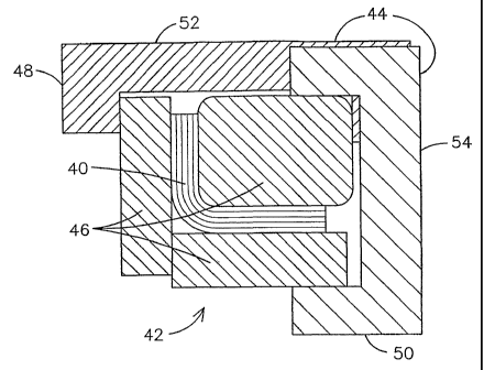
FIG. 3 illustrates another embodiment wherein a controlled amount of
pressure is applied to a CIVIC article 40 during a sintering step by the use
of
6
CA 02616475 2008-01-23
WO 2007/061398 PCT/US2005/026339
delta-alpha multiplier tooling 42. The term delta-alpha multiplier is used
herein to describe tooling that incorporates two or more members having
different coefficients of thermal expansion in order to provide a controlled
amount of pressure/force against a surface of an article upon heating of the
article. The article 40 in the example illustrated in FIG. 3 is an L-shaped
body
having plies of CMC material laid up along the legs of the L-shape and
extending around the non-planar elbow of the L-shape. Article 40 may be
formed of a material A having a coefficient of thermal expansion aA. The
article 40 has a thru-thickness dimension t. The article 40 is positioned at
least partially within portions of a first tooling member 44 exhibiting a
first
coefficient of thermal expansion, and a second tooling member 46 exhibiting a
second coefficient of thermal expansion higher than the first coefficient of
thermal expansion is disposed between the first tooling member 44 and the
article 40. Snug contact is maintained between all of the adjoining surfaces
at
room temperature when the article 40 is tooled. Coincident heating of the
article 40, the first tooling member and the second tooling member over a
temperature rise of AT will cause relatively greater expansion of the second
tooling member 46 compared to the expansion of the first tooling member 44,
thereby exerting a desired thru-thickness pressure against the article 40.
Because the L-shaped article 40 illustrated in FIG. 3 has legs extending in
two
perpendicular directions, the first tooling member 44 is designed to have two
hook portions 48, 50 shaped to present surfaces for capturing respective
portions of the second tooling member 46. Optionally, a first portion 52 of
the
first tooling member 44 may be formed of a material Y exhibiting a coefficient
of thermal expansion ay and a second portion 54 of the first tooling member
44 may be formed of a material X exhibiting a second coefficient of thermal
expansion ax different than ay. The sintering shrinkage change At in the thru-
thickness dimension t of the article 40 is accommodated by the differential
changes in the respective dimensions of the tooling members that occur as
the assembly is heated over the temperature range AT to a sintering
temperature. This relationship may be expressed as:
7
CA 02616475 2008-01-23
WO 2007/061398 PCT/US2005/026339
At=[L1-oy-(t.aA+h1-ax+w1-ax)]-AT
(1)
Thus, any separation force developed between the plies of the CMC material
A of article 40 due to anisotropic shrinkage may be resisted, while at the
same
time maintaining the pressure applied against the article 40 to a value low
enough to prevent undue consolidation of the CMC material, by proper
selection of the materials X, Y, Z of the various portions of delta-alpha
tooling
42. Such fixed displacement methods apply an initially high pressure that
subsequently relaxes due to sintering shrinkage and/or creep relaxation.
FIG. 4 is a partial cross-sectional view of a composite article 60
wherein a layer of a CMC material 62 is adjoined to a layer of a monolithic
ceramic material 64. One example of such a material is described in United
States patent 6,197,424 issued on March 6, 2001, and assigned to the
assignee of the present invention. The CMC material 62 includes a plurality
of plies 66, each ply 66 containing reinforcing fibers 68 disposed in a matrix
material 70. A top ply 66` has a top surface 72 adjoined to a bottom surface
74 of the monolithic material 64. A pressure P is applied to urge the adjoined
surfaces 72, 74 together while heating the composite article 60 to a sintering
temperature to bond the ceramic matrix composite material 62 to the
monolithic ceramic material 64. The pressure P is applied to a level
sufficiently high to overcome a separation force tending to separate the
adjoining surfaces 72, 74 resulting from differential shrinkage between the
ceramic matrix composite material 62 and the monolithic ceramic material 64.
This pressure also overcomes any separation force existing between the plies
66 of the CIVIC material 62 that may result from the non-linear component of
the weave of the fibers 68. The pressure may be limited to a level
sufficiently
low to maintain a desired level of porosity within the ceramic matrix
composite
material 62 and/or within the monolithic ceramic material 64. The pressure P
may be a uniform pressure for a planar article. Alternatively, the pressure P
may be varied along a surface of the article, particularly when the article
contains a non-planar section where a higher level of pressure may be
needed to overcome the separation forces generated in the non-planar region
8
CA 02616475 2008-01-23
WO 2007/061398 PCT/US2005/026339
by anisotropic shrinkage of the CMC material 62 and by differential shrinkage
between the CMC material 62 and the monolithic material 64. It is recognized
that the degree of porosity that is obtained may vary across the article in
accordance with such varying pressure and that in general the degree of
porosity will be reduced as the pressure is increased. A combination of a
varying the pressure along a surface of the article and varying the pressure
at
a particular point on the surface over time may be useful for more closely
controlling the resulting porosity to a desired value.
While various embodiments of the present invention have been shown
and described herein, it will be obvious that such embodiments are provided
by way of example only. Numerous variations, changes and substitutions
may be made without departing from the invention herein. Accordingly, it is
intended that the invention be limited only by the spirit and scope of the
appended claims.
9