Note: Descriptions are shown in the official language in which they were submitted.
CA 02616500 2011-04-28
STRAND-LIKE MATERIAL LAYING DEVICE FOR CUTTING THE
GROUND AND INSERTING STRAND-LIKE MATERIAL INTO THE
GROUND
Field of the Invention
The present invention relates generally to a strand-like material laying
device for
appliances for laying strand-like material of endless length, such as steel
pipes, conduits,
cables, etc., into a trench formed in the ground.
Background of the Invention
Various appliances have been suggested which include a device for forming a
trench
having substantially vertical side walls in the ground, and for laying strand-
like material of
endless length, such as conduits, pipes and cables, into the trench. It should
be noted that
"endless length" designates a material which is very long in comparison with
the length of
the device laying the material, and does not require that the material be of
infinite length.
Such appliances are described e.g. in WO 86/00356 Al, US 3,747,357, US
3,486,344, US
3,486,344, US 3,429,134, DE 1 189 602 Al, DE 32 45 625 Al, DE 25 29 285 Al, DE
28 06
379 Al or DE 491 887 BI and typically comprise a support vehicle, a blade
connected to and
supported by the support vehicle for lifting and lowering, and a feeding means
mounted in
connection with the blade for pivotal movement about a horizontal axis and
feeding the
strand-like material from a storage reel rotatably mounted on the support
vehicle, through an
internal guide channel into a subterranean trench formed by the blade immersed
into the
ground when moving the support vehicle. With such appliances, in a single step
a vertical
trench can be formed in the ground and a strand-like material can be fed into
the trench and
laid onto the base of the trench while the support vehicle is moved forwardly.
The above mentioned appliances are designed for laying a strand-like material
of
relative high flexibility, such as cables, wound on a storage reel. However,
such appliances
are not appropriate in cases where strand-like material of relatively low
flexibility and of
"endless" length, such as more rigid steel pipes like gas pipes, oil pipes,
etc., are to be laid.
1
CA 02616500 2008-02-29
Normally, strand-like material of the latter mentioned more rigid or less
flexible type is not
fed from a storage reel but rests on the ground surface prior to being laid
into the ground and
is picked up, fed along a curved path into a trench formed in the ground by
the appliance. In
order to reduce a risk of being damaged or broken due to falling below a
minimum allowable
bending radius of the strand-like material of the more rigid or less flexible
type to be laid,
the curved path must be set so as to assure a sufficiently large radius of
curvature, so that the
length of the known appliances becomes very large if more rigid strand-like
material is to be
laid into the trench.
Summary of the Invention
The present invention provides a strand-like material laying device for an
appliance for laying any kind of strand-like material into the ground. A
strand-like material
laying device according to the present invention is designed to lay a more
rigid strand-like
material such as steel pipes into the ground. A strand-like material laying
device according
to the present invention assures that a strand-like material to be laid can
smoothly be fed into
a trench formed in the ground without risking that a bending radius thereof
falls below a
minimum allowable bending radius which depends on the type of the strand-like
material to
be laid.
The present invention provides a strand-like material laying device for
immersing
into the ground to form a subterranean trench while being moved in a
longitudinal direction.
To this end the strand-like material laying device comprises a first unit for
cutting the ground
to form said trench and guiding said strand-like material into said trench,
said first unit
having a plurality of first elements which are connected in series like a
flexible chain. Each
of the plurality of first elements has at its front end a cutting edge wherein
the cutting edges
of two successive ones of the plurality of first elements are offset with
respect to each other
in depth direction of the strand-like material laying device so that a cutting
depth of the
strand-like material laying device increases in a direction opposed to the
direction of
movement thereof. Two successive ones of the plurality of first elements are
coupled with
each other for pivotal movement about an axis being substantially parallel to
the depth
direction of the strand-like material laying device, which corresponds to the
vertical
direction when using the strand-like material device.
2
CA 02616500 2008-02-29
Due to its flexibility in lateral direction by the chain-like series
connection of the
plurality of first elements for pivotal movement about a substantially
vertical axis the strand-
like material laying device allows for a compensation of changing lateral
forces acting on the
cutting and inserting elements when cutting and ploughing the ground. Lateral
forces acting
on the cutting and inserting elements when cutting and ploughing the ground
may change
between left and right sides as well as between front and rear sides of the
strand-like material
laying device i.e. in lateral and longitudinal direction of the strand-like
material laying
device, due to variations of ground conditions as regards the ground
constitution (gravel,
sand, clay, etc.), the existence of obstacles (stones, root systems, etc.)
included in the
ground, as well as atmospheric conditions within the ground (frost and frost-
free ground
sections).
Offsetting the cutting edges of respective two successive elements of the
plurality of
first elements in depth direction so that a working depth of the two
successive elements
increases in a direction opposed to the direction of movement of the strand-
like material
laying device enables the division of the overall longitudinal force acting on
the strand-like
material laying device when being moved forward, into a plurality of
longitudinal force
components each acting on a respective one of the cutting and inserting
elements. Thus a
risk for the strand-like material laying device when being moved in the
longitudinal direction
to experience a torque causing the strand-like material laying device to tilt
about a front end
thereof is reduced.
A pivotal movement of said two successive ones of the plurality of first
elements
may be limited to a predetermined maximum angle of pivotal movement. This
maximum
angle of pivotal movement of said two successive ones of the plurality of
first elements may
be adjustably set on the basis of the type of strand-like material to be laid
into the trench
formed in the ground. In most cases it may be sufficient if said angle of
pivotal movement is
limited to be within a range of 1 and 3 degrees.
Furthermore, different cutting edges may be exchangeably mounted to each
element
of the plurality of first elements, so as to be able to adapt these first
elements to any
prevailing ground conditions.
In order to generate downwardly directed reaction forces, the cutting edges
may
be inclined slightly downward from a horizontal level so as to terminate at a
bottom end of
3
CA 02616500 2008-02-29
the respective element and form a blade nose projecting in the direction of
movement of the
strand-like material laying device.
At least one of the plurality of first elements may have as means for
controlling the
working depth thereof, a fin-like shoe coupled to said nose for pivotal
movement about
an axis which is substantially perpendicular with respect to the depth
direction and direction
of movement of the strand-like material laying device. Preferably, a pivotal
movement of
said fin-like shoe is limited to a predetermined angle of pivotal movement.
Furthermore,
preferably, said fin-like shoe is exchangeably mountable to the at least one
of the plurality of
first elements.
Said fin-like shoe may comprise at its front end an exchangeably mounted
cutting
tip projecting in the direction of movement of the strand-like material laying
device.
Different cutting tips can be inserted in the shoe, for adaptation of the
cutting and inserting
elements to various different prevailing ground conditions.
Furthermore, at least one of the plurality of first elements, preferrably the
first
two of the plurality of first elements, may have at its blade nose an
exchangeably mounted
cutting tip projecting in the direction of movement of the strand-like
material laying device.
Different cutting tips can be inserted in the blade nose, for adaptation of
the cutting and
inserting elements to various different prevailing ground conditions. The
strand-like material
laying device may further comprise a second unit for guiding said strand-like
material into
said trench and laying it at a bottom of said trench, which second unit is
coupled to the first
unit of first unit having said plurality of first elements, for pivotal
movement about an axis
which is substantially parallel to the depth direction of the strand-like
material laying device.
This second unit may comprise a plurality of second elements which are
connected in series
like a flexible chain, and wherein two successive ones of said plurality of
second elements
are coupled with each other for pivotal movement about an axis being
substantially parallel
to a depth direction of the strand-like material laying device, i.e. a
substantially vertical axis,
to allow for a compensation of lateral forces acting on the strand-like
material laying device
when ploughing the ground. This second unit is primarily for supporting the
strand-like
material laying device and serves to smoothly lay the strand-like material
into the trench
formed by the plurality of first elements.
4
CA 02616500 2008-02-29
The two successive ones of said plurality of second elements may further be
coupled
with each other at their bottom ends for pivotal movement about an axis which
is
substantially parallel to a width direction of the strand-like material laying
device, to allow
for an adaptation of the strand-like material laying device as a whole when
crossing a hill or
the like.
Preferably, a bottom end of said second unit is aligned with a bottom end of a
trailing one of the first group of plurality of first elements in depth
direction of the strand-
like material laying device to form a substantially continuous sole (i.e.,
external bottom
surface) for sliding on the base of the trench.
Furthermore, the strand-like material laying device according to the present
invention may comprise an internal guiding channel extending continuously over
the overall
length of the strand-like material laying device from an inlet opening at a
front end thereof
towards an outlet opening at a rear end thereof, for guiding a strand-like
material through the
strand-like material laying device into a trench formed by the strand-like
material laying
device.
Taking account of maintaining a minimum allowable bending radius of the strand-
like material to be laid the guiding channel is preferably formed along a
curve having a
radius of curvature which is set depending on a minimum allowable bending
radius of the
strand-like material to be laid in the trench.
Moreover, preferably, the inlet opening opens in a substantially horizontal
direction for receiving a strand-like material lying on the ground ahead of
the strand-like
material laying device, and the outlet opening opens in a substantially
horizontal direction on
a level with the base of a trench formed by the strand-like material laying
device. To enable
a smooth feeding of the strand-like material through the internal guiding
channel, the strand-
like material laying device may have at its front end and rear end supporting
rolls for
supporting the strand-like material fed into the inlet opening and out of the
outlet opening,
respectively.
Furthermore, a leading one of the first group of a plurality of first elements
may
comprise at its front end a towing eye for connecting to a towing rope, the
towing eye being
located beneath the inlet opening of the guiding channel. Therefore, according
to an
embodiment of the present invention the strand-like material laying device is
pulled by
5
CA 02616500 2008-02-29
means of the towing rope. Furthermore, according to an embodiment of the
present
invention, the towing eye may be located beneath the inlet opening of the
guiding channel in
order to cause a traction force transmitted by the towing rope to act directly
at the strand-like
material laying device at a position close to the ground.
Furthermore, another embodiment of the present invention provides an appliance
for
the subterranean laying of strand-like material, comprising a strand-like
material laying
device as above mentioned, and an off-road steerable chassis frame supporting
the strand-
like material laying device by straddling it between a pair of left wheels and
the pair of right
wheels and enabling to vertically lift and lower the strand-like material
laying device from
and towards the ground, respectively.
The chassis frame may be of the articulated frame type having a central
structural
framework which is supported on four wheels by means of an articulating
linkage assembly
associated with each wheel and the framework.
Preferably, the strand-like material laying device is connected at its front
end side to
the central structural framework for pivotal movement about an axis being
substantially
parallel to a width direction of the strand-like material laying device, and
is coupled at its
rear end side to means for vertically lifting and lowering the strand-like
material laying
device, which means is vertically slidably supported by the central structural
framework.
Brief Description of the drawings
The accompanying drawings, where like numerals indicate like components,
illustrate a preferred embodiment of the invention.
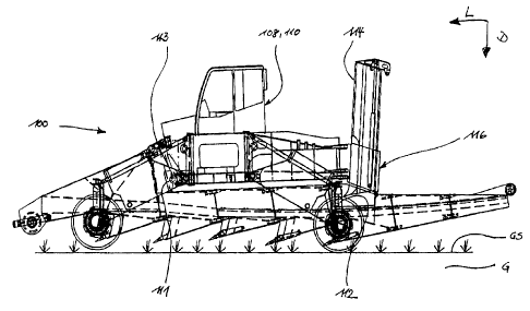
Fig. 1 is a side view schematically showing an appliance carrying a strand-
like
material laying device according to an embodiment of the present invention.
Fig. 2 is a side view schematically showing the appliance of Fig. 1 in a state
where
the strand-like material laying device according to an embodiment of the
present invention is
immersed into the ground.
Fig. 3 is a top view schematically showing the appliance of Fig. 1.
Figs. 4a and 4b are side views showing the strand-like material laying device
according to an embodiment of the present invention.
Figs. 5a and 5b are top views showing the strand-like material laying device
according to an embodiment of the present invention.
6
CA 02616500 2008-02-29
Fig. 6a is a side view schematically picking out a single element of the
strand-like
material laying device according to an embodiment of the present invention.
Fig. 6b is a cross-sectional side view schematically showing a coupling
portion of
two elements of the strand-like material laying device along a dashed line A-A
in Fig. 5b.
Fig. 6c is a cross-sectional top view schematically showing an upper hinge of
the
coupling portion shown in Fig. 6b.
Figs. 7a and 7b are top and partial side views schematically showing a lower
portion of a single element of the strand-like material laying device.
Figs. 8a and 8b are top and partial side views schematically showing a fin-
like shoe
to be attached to a lower portion of another single element of the strand-like
material laying
device.
Figs. 8c and 8d are top cross-sectional and partial side views schematically
showing
the fin-like shoe of Figs. 8a and 8b in a state attached to a lower portion of
the another single
element of the strand-like material laying device.
Detailed description of the preferred embodiments
Reference will now be made with Figs. 1 to 8 to the structure and effects of
referred
embodiments of the invention.
Referring to Figs. 1 to 8, the ground surface is denoted by GS, the ground is
denoted
by G, a trench formed by a strand-like material laying device according to the
present
invention is denoted by T, and a strand-like material laid in the trench T is
denoted by M.
Arrows L, D, and W denote a longitudinal direction (or direction of movement),
a depth
direction, and a width direction (or lateral direction), respectively, of the
strand-like material
laying device 10.
Figs. 1 to 8 show a strand-like material laying device 10 according to an
embodiment of the present invention, which is carried by an off-road
steerable, four-wheeled
chassis frame 100 as seen from Figs. 1 to 3. As it is illustrated in Fig. 2,
the strand-like
material laying device 10 carried by the chassis frame 100 is configured to
substantially
vertically immerse into the ground G when being moved or pulled in the
longitudinal
direction L, thereby to excavate or cut the ground G and form a trench T, to
smoothly feed
the strand-like material M, such as a steel pipe, cable, etc., from the ground
G over its entire
length into the thus formed trench T and to smoothly lay it onto a base B of
the thus formed
trench T.
7
CA 02616500 2011-04-28
The chassis frame 100 as depicted in Figs. 1 to 3 generally includes a central
structural framework 102 which is supported on four wheels 104 by means of an
articulating
linkage assembly 106 associated with each wheel 104 and central structural
framework 102.
The central structural framework 102 may serve as a support for a cabin 108
and/or power
section 110 depicted in Figs. 1 to 3 and a control box not shown. Other items,
such as body,
driver's seat, etc. (not shown) may be supported on frame in a conventional
manner. The
articulating linkages 106 are configured to move the four wheels 104
independently from
each other in both horizontal and vertical directions with respect to the
chassis frame 100.
An example of a possible chassis frame 100 is SpiderPlow used by SpiderPlow
Services a specialized pipeline installation company, operating in western
Canada and the
United States, and engineered and manufactured in Germany by Walter
Fockersperger
GmbH. Technical details of the chassis frame 100 and linkages 106 can be
obtained from
SpiderPlow Services or Walter Fockersperger GmbH, Germany.
As it is seen from Figs. 1, 2 and 3, the strand-like material laying device 10
is
supported astraddle by the chassis frame 100 between the pair of left wheels
and the pair of
right wheels. More specifically, the strand-like material laying device 10 is
attached to the
chassis frame 100 via support bolts which extend in width direction W through
support holes
11, 12, 13 provided at the strand-like material laying device 10, as shown in
Figs. 4a and 4b,
and are held at support portions 111, 112, 113 provided at the chassis frame
100. As
illustrated in Figs. 1 and 2 a first support portion 111 is provided at a
front end side of the
central structural framework 102, while a second support portion 112 is
provided at a blade
means 114 which is supported at a rear end side of a longitudinal direction
extension 103 of
the central structural framework 102 by means of a hydraulically operated
lifting equipment
116. An additional third support portion 113 is provided at a front end side
of the central
structural framework 102 at a predetermined distance above the first support
portion 111.
While the first and second support portions 111, 112 have the function to
pivotally carry the
strand-like material laying device 10 on the chassis frame 100, the third
support portion 113
is primarily for supporting the strand-like material 10
`Trade-mark
8
CA 02616500 2007-12-28
Express Mail Label No. EV840657891US
Attorney Docket No. 616033000300
in width direction W in order to prevent the strand-like material laying
device 10
from tilting with respect to the chassis frame 100 about a longitudinal axis.
By simultaneously operating the articulating linkages 106 and the lifting
equipment 116 the strand-like material laying device 10 carried by the chassis
frame
100 can be moved in the depth direction D, i.e., can be lowered to immerse
into the
ground G as shown in Fig. 2, or lifted out of the ground G as shown in Fig. 1.
While in operation, the strand-like material laying device 10 can be divided
in
longitudinal direction L in a front or first unit 20 and a rear or second unit
40 as shown
in Fig. 2. Referring to Fig. 2, the first unit 20 has the primary function of
cutting the
ground G and forming the trench T having substantially vertical side walls and
a base B
in a predetermined depth defined by the depth of immersion of the strand-like
material
laying device 10, and internally feeding the strand-like material M lying on
the ground
surface GS in front of the strand-like material laying device 10 into the
trench T when
being moved in the longitudinal direction L. The second unit 40 has the
primary
function of internally feeding and smoothly laying the strand-like material M
onto the
base B of the thus formed trench T. When being immersed into the ground G by
means
of lowering the central structural framework 102 and blade means 114, and
being
moved in the longitudinal direction L both the first unit 20 and the second
unit 40 will
align themselves in a substantially vertical direction due to side forces
laterally acting
from the vertical side walls of the trench T onto the strand-like material
laying device
10. In summary, the first unit 20 and the second unit 40 of the strand-like
material
laying device 10 cooperate to form a substantially trench T in the ground G
and to act
like a chute to smoothly feed and lay a strand-like material M from the ground
surface
GS towards the base B of trench T.
As can be best seen from Figs. 4a, 4b, 5a and 5b, the first unit 20 and the
second
unit 40 are each formed of a plurality of first elements, more specifically
five first
elements 21, 22, 23, 24, 25, and a plurality of second elements, more
specifically two
second elements 41, 42, respectively, which are connected to each other in
series like a
flexible chain. While the first elements 21, 22, 23, 24, 25 are pivotally
coupled with
each other about an axis which is substantially parallel to the depth
direction D, the
second elements 41, 42 are pivotally coupled with each other and with the last
one 25 of
9
1a-896778
CA 02616500 2007-12-28
Express Mail Label No. EV840657891US
Attorney Docket No. 616033000300
the first elements 21, 22, 23, 24, 25 about an axis which is substantially
parallel to the
depth direction D and an axis which is substantially parallel to the width
direction W.
Each of the plurality of first and second elements is formed of steel plates
to have
a hollow rigid configuration which is closed at the left and right side walls,
at the
bottom and top sides, and at the front and rear sides except where a later
discussed
internal guiding channel 70 enters and exits. A width of each of the plurality
of first and
second elements is set so that the internal guiding channel 70 can be formed
to feed the
strand-like material M internally through the strand-like material laying
device 10 as
illustrated in Figs. 2, 4a and 4b.
The five elements 21, 22, 23, 24, 25 of the first unit 20 are each structured
to
have a depth directional lower front end portion 21a, 22a, 23a, 24a, 25a and a
depth
directional upper front end portion 21b, 22b, 23b, 24b, 25b.
The lower front end portions 21a, 22a, 23a, 24a, 25a taper off in longitudinal
direction L to define each a cutting edge 21c, 22c, 23c, 24c, 25c at their
front ends as
can be best seen from Figs 5a, 5b, 7a and 8c. As shown in Figs. 1, 2, 4a and
4b,
elements 21, 22, 23, 24, 25 are staggered with respect to each other in depth
direction
D of the strand-like material laying device 10 so that the lower front end
portions 21 a,
22a, 23a, 24a, 25a and thus the cutting edges 21c, 22c, 23c, 24c, 25c of
respective two
successive ones of the five elements 21, 22, 23, 24, 25, i.e, cutting edges
21c, 22c of
elements 21, 22, cutting edges 22c, 23c of elements 22, 23, cutting edges 23c,
24c of
elements 23, 24, and cutting edges 24c, 25c of elements 24, 25, are offset
with respect
to each other in depth direction D of the strand-like material laying device
10.
Accordingly, a working depth of elements 21, 22, 23, 24, 25 increases in a
direction
opposed to the longitudinal direction L of the strand-like material laying
device 10. As
it is seen from Figs. 4a and 4b, the cutting edges 21c, 22c, 23c, 24c, 25c of
elements
21, 22, 23, 24, 25 are formed so as to be inclined slightly downward from the
horizontal direction, terminate at a front bottom end portion in a nose
portion 21d, 22d,
23d, 24d, 25d and project forward in the longitudinal direction L. Cutting
edges 21c,
22c, 23c, 24c, 25c may be fixed to the front ends of elements 21, 22, 23, 24,
25, e.g. by
welding. Alternatively, cutting edges 21c, 22c, 23c, 24c, 25c may be
exchangeably
mounted to the front ends of elements 21, 22, 23, 24, 25, e.g. by way of
positive
locking and bolting.
la-896778
CA 02616500 2011-04-28
Moreover, as it is seen from Figs. 4a and 4b the soles (i.e., the external
bottom
surfaces) 21e, 22e, 23e, 24e of each element 21, 22, 23, 24 are inclined in a
rear-and-
upward direction to define a clearance angle a between soles 2le, 22e, 23e,
24e and the
longitudinal direction L when cutting the ground G. A sole 25e of element 25
extends in
a direction substantially parallel with the longitudinal direction L to
smoothly transition
to a soles 41e, 42e of elements 41, 42 of the second unit 40.
Elements 21, 22 each comprise, as means for controlling the working depth
thereof, an exchangeably mounted chisel-like cutting tip 21f, 22f projecting
in the
direction of movement of the strand-like material laying device 10. Cutting
tips 21f, 22f
are screwed onto noses 21d, 22d about a longitudinal direction thereof. Fig.
7a and 7b
illustrate in more detail the cutting edge portion of element 22. The
structure of the
cutting edge portion of element 21 may be similar to that of element 22, so a
further
description thereof is omitted.
As opposed to elements 21, 22, elements 23, 24, 25 each comprise, as means for
controlling the working depth thereof, a fin-like shoe 30, 31, 32 coupled to
respective
noses 23d, 24d, 25d for pivotal movement about an axis being parallel with
respect to
the width direction W of the strand-like material laying device 10. Figs. 8a
and 8b
illustrate in more detail' the structure of the fin-like shoe 30, while Figs.
8c and 8d
illustrate in more detail the cutting edge portion of element 23 having the
fin-like shoe
30. As follows from Figs. 8a, 8b and 8c, fin-like shoe 30 has a U-shaped
structure
comprising two rearwardly extending leg portions 30c, 30d that are disposed
laterally
outside the side walls of element 23 to partially embrace element 23, and a
cutting tip
30b exchangeably mounted to a front part of the U-shade structure as a means
for
controlling the working depth of element 23. Cutting tip 30b is screwed onto
the nose
23d about a longitudinal direction thereof. The fm-like shoe 30 is supported
at nose
portion 23d like a lever for pivotal movement about an axis 30a being
substantially
parallel with respect to the width direction W of the strand-like material
laying device
10. As it is illustrated in Fig. 8d a relative angular position of the fin-
like shoe 30 with
respect to element 23 can be adjusted within a predetermined range of pivotal
movement at various positions defined by bolt inserting holes 35 provided at
the
element 23, by inserting a bolt through bolt inserting holes 34 formed at a
rear
portion of leg portions 30c, 30d and an appropriate one of bolt inserting
holes 35
11
CA 02616500 2011-04-28
formed at element 23. A relative angular position of the fin-like shoe 30 with
respect
to the element 23 is set depending on the constitution of the ground. In a not
shown
alternative embodiment the rearward extending leg portions 30c, 30d may be
hingedly
coupled with a control mechanism (e.g., a hydraulically operated control
mechanism)
allowing to continuously pivot the fin-like shoe 30 within a predetermined
range of
pivotal movement during operation of the strand-like material laying device.
Since the
structure of the cutting edge portions of elements 24, 25 and fin-like shoes
31, 32
correspond to that of element 23 and fin-like shoe 30, a further description
thereof is
not included.
A supporting mechanism 65 for the strand-like material M is attached, e.g.
bolted, to the front end upper portion 21b of element 21, as it is seen from
Fig. 4a. The
supporting mechanism 65 includes a housing 66 and a supporting roll 67 which
is
supported for rotation about an axis 68 being substantially parallel with
respect to the
width direction W, by the housing 66. Moreover, as it is seen from Fig. 3, a
row of
three towing eyes 69 may be provided in width direction W at a front end of
the
supporting mechanism 65 for connecting the strand-like material laying device
10 to a
towing rope (not shown).
The upper front end portions 22b, 23b, 24b, 25b of elements 22, 23, 24, 25
which
are located behind the first or leading element 21 are each coupled with a
rear end of a
respectively preceding one of elements 21, 22, 23, 24 for a limited pivotal
movement
about an axis being substantially parallel with the depth direction D of the
strand-like
material laying device 10. More specifically, as illustrated in Figs. 4a and
4b the rear
end portions 21g, 22g, 23g, 24g of elements 21, 22, 23, 24 are each coupled
with the
upper front end portions of elements 22, 23, 24, 25 by a pair of upper and
lower hinges
50. As illustrated by Fig. 6a these hinges 50 include each a pair of lugs 51
which extend
rearwardly from a rear end portions 21g, 22g, 23g, 24g.of elements 21, 22, 23,
24 and
carry a bolt-like hinge pin 54 illustrated in Fig. 6b, extending substantially
in the depth
direction D of the strand-like material laying device 10. The upper front end
portions
22b, 23b, 24b, 25b of elements 22, 23, 24, 25 are each provided with upper and
lower
forwardly extending lugs 52 which are each sandwiched between a corresponding
one
of the pairs of rearwardly extending lugs 51 and have a hinge pin
accommodating bore
through which a corresponding one of the hinge pins 54 passes for a sliding
motion.
12
CA 02616500 2007-12-28
Express Mail Label No. EV840657891US
Attorney Docket No. 616033000300
Each of the pairs of rearwardly extending lugs 52 includes a means of abutment
53 for a
front end 52a of the forwardly extending lug 52 if a predetermined angle of
pivotal
movement a about an axis defined by hinge pin 54 is exceeded in clockwise or
anti-
clockwise direction. As for the structure of the hinges 50 it is referred to
Figs. 6b and 6c
showing a structure of hinges 50 for coupling elements 41 and 25, which
structure
corresponds in principle to that of the hinges 50 for coupling elements 21,
22, 23, 24,
25. The rearwardly extending lugs 51, the hinge pins 54, and the forwardly
extending
lugs 52 thus form hinges 50 between two successive ones of elements 21, 22,
23, 24, 25
(as well as between elements 41, 42) which allow a pivotal movement about an
axis
which is defined by hinge pin 54 to a limited extent, e.g. by I degree.
A rear end upper portion 22h of element 22 and the front end upper portion 25b
of
element 25 are provided with support holes 11, 12 for pivotally attaching the
strand-like
material laying device 10 to the chassis frame 100. Moreover, the rear end
upper portion
22h of element 22 provides at a distance above the support hole 11 an
elongated bore 13
for the accommodation of a front end portion of a not depicted sliding rod
which is
pivotally attached at its other end portion at the chassis frame 100. To fix
the strand-like
material laying device 10 in the transport position shown in Fig. 1 there is
further
provided a cross-hole 14 crossing the elongated bore 13 and positively
engaging with a
not depicted bolt provided at the chassis frame 100 in the transport position
to prevent
the strand-like material laying device 10 from laterally tilting with respect
to the chassis
frame 100, during a transport thereof.
As can be best seen from Figs. 4b and 5b, the second unit 40 is formed of
elements 41, 42 which are connected to each other in series like a flexible
chain. As
opposed to the first elements 21, 22, 23, 24, 25 which are pivotally coupled
with each
other only about an axis which is substantially parallel to the depth
direction D, the
second elements 41, 42 are pivotally coupled with each other and with the last
one 25 of
the first elements 21, 22, 23, 24, 25 about both an axis which is
substantially parallel to
the depth direction D and an axis which is substantially parallel to the width
direction
W. Hinges 50 pivotally coupling elements 41, 42 with each other and element 41
with
element 25 differ from hinges 50 between elements 21, 22, 23, 24, 25 only in
the
following feature. The upper forwardly extending lugs 52 of elements 41 and 42
comprise each instead of a round hinge pin accommodating bore an elongated
hinge pin
13
la-896778
CA 02616500 2011-04-28
accommodating hole 52b extending in the longitudinal direction L as
illustrated in Fig.
6b. Accordingly, the hinge pins 54 can slide within the hinge pin
accommodating holes
52b provided at the upper forwardly extending lugs 52b of elements 41, 42 in
longitudinal direction L. On the other hand, the lower forwardly extending
lugs 52 of
elements 41 and 42 comprise each a hinge pin accommodating bore similar to the
upper
and lower forwardly extending lugs 52 of elements 21, 22, 23, 24, 25, in which
the
hinge pins 54 are accommodated with a small play only sufficient to enable the
hinge
pins 54 to slightly incline within the hinge pin accommodating bores.
Therefore, an axis
for a pivotal movement of elements 41, 42 with respect'to elements 25, 41,
respectively,
is provided at the interface of bottom ends of elements.41, 25 and 41, 42,
which is
substantially parallel to the width direction W. Moreover, a pivotal movement
of
elements 41, 42 with respect to elements 21, 41, respectively, is limited by
the length of
the elongated hinge pin accommodating hole 52b provided in the upper forwardly
extending lugs 52b of elements 41, 42 to a predetermined angle of pivotal
movement a
which is e.g. 1 to 10 degrees.
As can be seen from Figs. 4a and 4b elements 41 and 42 are aligned with each
other and with respect to element 25 in depth direction D so that their bottom
ends 41 e,
42e are on substantially the same level with a bottom end of element 25.
A supporting mechanism 60 for the strand-like material M is attached, e.g.
bolted,
to the rear end upper portion 42g of element 42 as it is seen from Fig. 4b.
The
supporting mechanism 60 includes a rear housing 61 and a supporting wheel 62
which is
supported for rotation about an axis 63 being substantially parallel with
respect to the
width direction W, by the rear housing 61.
Furthermore, the strand-like material laying device 10 comprises an internal
guiding channel 70 which is constituted by guiding channel portions 70a, 70b,
70c, 70d,
70e, 70f, 70g each being provided in one of elements 21, 22, 23, 24, 25, 41,
42 so as to
extend continuously over the overall length of the strand-like material laying
device 10
from an inlet opening 71 at a front end of element 21, which is located
immediately
above the supporting mechanism 65, thereof towards an outlet opening 72 at a
rear end
of element 42, which is located immediately below the supporting mechanism 60,
as
seen from Figs. 4a and 4b, for guiding the strand-like material M through the
strand-like
material laying device 10 into the trench T. Taking account of maintaining a
minimum
14
CA 02616500 2007-12-28
Express Mail Label No. EV840657891US
Attorney Docket No. 616033000300
allowable bending radius of the strand-like material T the guiding channel 70
is formed
through the strand-like material laying device 10 along a smoothly bent curve
having a
radius of curvature R which is set depending on a minimum allowable bending
radius of
the strand-like material T.
As it is seen from Fig. 4 the inlet opening 71 is set so as to open in a
substantially
horizontal direction for receiving the strand-like material T laying on the
ground G
ahead of the strand-like material laying device 10, and the outlet opening 72
opens in a
substantially horizontal direction on a level with the base B of the trench T
formed by
the strand-like material laying device 10.
Furthermore, in order to obtain a smooth guidance of the strand-like material
M
through the internal guiding channel 70 portions the internal guiding channel
70
expected to be in friction with the strand like material may be provided with
guiding
means 80 as shown in Figs. 9a, 9b, 9c, 10a, 10b. Albeit such means are shown
in
combination with element 42 only, such means may be provided at any other
friction
portions as well, e.g. at any portions where the strand-like material M comes
into
contact with the sidewalls defining the internal guiding channel 70. These
guiding
means 80 may include supporting members 81 which are attached via an
elastically
deformable material 81b, e.g. a rubber material, at an upper side wall 71 of
the internal
guiding channel portions 70a, 70b, 70c, 70d, 70e, 70f, 70g of the
corresponding one of
elements 21, 22, 23, 24, 25, 41, 41, and have a curved surface 81a which is
provided
with a low friction coating 82 to support the strand-like material M as
illustrated in Fig.
9a. Alternatively, these guiding means 80 may include supporting rolls 85
which are
each rotatably held by the corresponding one of elements 21, 22, 23, 24, 25,
41, 41, and
have a curved surface 85a which is provided with an elastic deformable coating
86 to
support the strand-like material M as illustrated in Fig. 10b.
Although the present invention has been described in connection with a
specific
preferred embodiment for instructional purposes, the present invention is not
limited
thereto. Accordingly, various modifications, adaptations, and combinations of
various
features of the described embodiments can be practiced without departing from
the
scope of the invention as set forth in the claims.
la-896778