Language selection

Search

Patent 2616983 Summary

Third-party information liability

Some of the information on this Web page has been provided by external sources. The Government of Canada is not responsible for the accuracy, reliability or currency of the information supplied by external sources. Users wishing to rely upon this information should consult directly with the source of the information. Content provided by external sources is not subject to official languages, privacy and accessibility requirements.

Claims and Abstract availability

Any discrepancies in the text and image of the Claims and Abstract are due to differing posting times. Text of the Claims and Abstract are posted:

  • At the time the application is open to public inspection;
  • At the time of issue of the patent (grant).
(12) Patent Application: (11) CA 2616983
(54) English Title: FIBRE OPTIC LIGHTING SYSTEM FOR DRINK TAPS
(54) French Title: SYSTEME D'ECLAIRAGE PAR FIBRE OPTIQUE POUR ROBINETS DE DISTRIBUTION DE BOISSONS
Status: Dead
Bibliographic Data
(51) International Patent Classification (IPC):
  • B67D 1/08 (2006.01)
(72) Inventors :
  • FERNANDEZ-ESPANA GARCIA, CARLOS (Spain)
(73) Owners :
  • FERNANDEZ-ESPANA GARCIA, CARLOS (Spain)
(71) Applicants :
  • FERNANDEZ-ESPANA GARCIA, CARLOS (Spain)
(74) Agent: SIM & MCBURNEY
(74) Associate agent:
(45) Issued:
(86) PCT Filing Date: 2006-05-19
(87) Open to Public Inspection: 2007-02-01
Availability of licence: N/A
(25) Language of filing: English

Patent Cooperation Treaty (PCT): Yes
(86) PCT Filing Number: PCT/ES2006/000268
(87) International Publication Number: WO2007/012677
(85) National Entry: 2008-01-28

(30) Application Priority Data:
Application No. Country/Territory Date
U200501787 Spain 2005-07-22

Abstracts

English Abstract


The invention relates to a fibre optic lighting system for drink taps. The
inventive system consists of an external light-emitting core from which light
is conveyed by means of fibre optic into a drink tap comprising a rigid plate
to which the fibre optic is fixed. The aforementioned plate is placed inside a
structure which is made from a light-diffusing material and which is covered
with a light-refracting resin. The external light-emitting core is formed by a
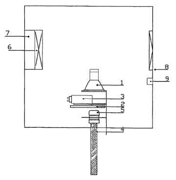
ventilator (6), inlet (8) and outlet (7) ventilation conduits, a halogen lamp
(1), a flashing and/or coloured disk (2) which rotates by means of a motor (3)
and a harness of fibre optic cables (4) which are joined at an optical port
(5).


French Abstract

L'invention concerne un système d'éclairage par fibre optique pour robinets de distribution de boissons. Ce système comprend un noyau émetteur de lumière externe à partir duquel la lumière est transportée à l'aide d'une fibre optique à l'intérieur d'un robinet de distribution. Ce robinet de distribution se compose d'une plaque rigide sur laquelle est fixée la fibre optique, la plaque étant elle-même disposée à l'intérieur d'une structure constituée d'une matière qui diffuse la lumière, recouverte d'une résine qui réfléchit la lumière. Le noyau émetteur de lumière externe comprend un ventilateur (6), des conduits de ventilation d'entrée (8) et de sortie (7), une lampe halogène (1), un disque de couleur et/ou à intermittence (2) qui tourne grâce à un moteur (3) et un harnais de câbles de fibre optique (4) couplés au niveau d'un port optique (5).

Claims

Note: Claims are shown in the official language in which they were submitted.


-4-


CLAIMS


1.- A fiber optic lighting system for drink taps, characterized by an external
light-
emitting core from which light is conveyed by means of fiber optic to the
inside of a
drink tap, comprising a rigid plate to which the fiber optic is fixed and this
plate in turn is
placed inside a structure which is made from a light-diffusing material
covered by a
light-refracting resin.
2.- A fiber optic lighting system for drink taps according to claim 1,
characterized by an external light emitter formed by a ventilator (6), inlet
(8) and outlet
(7) ventilation conduits, a halogen lamp (1), a flashing and/or colored disk
(2) rotating
through a motor (3) and a harness of fiber optic cables (4) which are joined
at an
optical port (5).
3.- A fiber optic lighting system for drink taps according to claim 1,
characterized
by a rigid plate containing a thermally insulated or non-thermally insulated
pipe (11), by
a harness of fiber optic (4) distributing the fiber optic cables (12) to the
different fixing
points (10) located on a rigid plate through which the light will be conducted
to the
inside of the drink tap.
4.- A fiber optic lighting system for drink taps according to claim 1,
characterized by a housing inside of which the rigid plate is introduced, this
housing
being formed by a light-diffusing material (14) in turn coated with a light-
refracting resin
(13).

Description

Note: Descriptions are shown in the official language in which they were submitted.


CA 02616983 2008-01-28
-~-

FIBER OPTIC LIGHTING SYSTEM FOR DRINK TAPS
Obiect of the Invention
The present specification relates to a Utility Model relating to a fiber optic
lighting system for drink taps, the purpose of which is to continuously
project points of
flashing and/or color changing light inside the drink tap. At the same time it
prevents
the transmission of heat emitted by the light inside the actual tap.
The system is made up of a light emitter located in the outer part of the
drink
tap, connected to the mains power supply, and of a harness of fiber optic
cables
through which the light is conveyed from the light emitter to the drink tap
cavity where
the fiber optic cables are housed and distributed to obtain the desired
lighting.
Field of the Invention
This fiber optic lighting system can be applied in the industry dedicated to
the
manufacture of apparatuses and instruments for light conduction, distribution,
transformation, regulation and control.
Background of the Invention
The applicant is aware of the existence today of a plurality of apparatuses
and
instruments for electricity and light conduction, distribution, accumulation,
regulation
and control.
The applicant is also aware of the existence of decorative and functional
fiber
optic lighting systems operating through a light-emitting core and a harness
of fiber
optics.
Today there is conventional lighting for display cases, closets and cooling
chambers using discharge, incandescent, fluorescent and halogen lamps. There
are
also conventional types of colored light-emitting lamps.
These traditional systems do not allow the light to flash and change colors.
These systems furthermore generate heat inside the actual drink tap cavity,
whereby
causing an unwanted increase of the temperature of the pipe carrying the
liquid.
The obvious solution to the drawbacks existing today in this matter would be
to
have a lighting system that allowed flashing and color change inside the
actual drink
tap. The fiber optic system further allows extracting a heat source from
inside the drink
tap since the lighting fiber optic does not transmit heat.
However, the applicant is not aware of the current existence of an invention
that
allows color changing and/or flashing lighting that is adapted to drink taps
which in turn


CA 02616983 2008-01-28

-2-
carries out the function of preventing a temperature increase inside the drink
tap.
Description of the Invention
The fiber optic lighting system for drink taps proposed by the invention is
configured as an evident novelty that allows the inner lighting of drink taps
with color
changing and/or flashing light. The fiber optic lighting system in turn does
not generate
heat inside the actual drink tap, since the light-emitting and heat-generating
focal point
is outside of such tap and the fiber optic cables propagate the light from the
external
light emitter towards the cavity without transmitting heat.
More specifically, the fiber optic lighting system for drink taps object of
the
invention comprises a closed external light-emitting core containing a
ventilator, the
lamp, the motor for rotating the flashing and/or colored disk and the flashing
and/or
colored disk itself, which will be responsible for producing the color change
and/or the
flashing inside the drink tap. A series of fiber optic cables conveying said
light to the
drink tap cavity come out of this emitting core; these fibers are fixed on a
rigid plate
located inside the tap cavity, which has a pipe attached thereto that may or
may not be
thermally insulated and through which the drink circulates. This plate is in
turn enclosed
inside a structure made from light-diffusing material to which resin is fixed
therearound
with light-refracting properties. This assembly basically forms the lighted
structure of
the tap.
Three sheets of drawings are attached to the present specification as an
integral part thereof, showing the following with an illustrative and non-
limiting
character:
Figure 1 shows an upper view of the external drink tap light emitter.
Figure 2 shows the front of the plate inside the inventive system where the
fiber
optic for lighting the drink tap is fixed.
Figure 3 shows the housing of the tap formed by the light-refracting material
plus the also light-refracting resin.
Preferred Embodiment of the Invention
A breakdown of the fiber optic lighting system for drink taps can be observed
in
Figures 1, 2 and 3, said system comprising an external emitting core outside
the tap
connected to the mains power supply, said emitter being enclosed in a casing
with
forced ventilation through an air inlet (8) and an air outlet (7), the emitter
further
comprising a ventilator (6), a halogen lamp (1), a flashing and/or colored
disk (2)
rotating through a motor (3) and a harness of fiber optic cables (4) which are
joined at
an optical port (5) that will receive the light from the halogen lamp (1). The
harness of


CA 02616983 2008-01-28

-3-
fiber optic cables (4) distributes the fiber optic cables (12) to the
different fixing points
(10) arranged on the rigid plate (Figure 2) inside the tap for fixing the
fiber optic cable;
said plate will be covered with a structure which is made from a light-
diffusing material
(14) in turn coated with light-refracting resin (13), see Figure 3.
It is considered unnecessary to extend this description so that a person
skilled
in the art may understand the scope of the invention and the advantages
derived from
it.
The materials, shape, size and arrangement of the elements may vary provided
that this does not alter the essential features of the invention.
The terms used in this description must always be interpreted in a broad and
non-limiting manner.
Representative Drawing
A single figure which represents the drawing illustrating the invention.
Administrative Status

For a clearer understanding of the status of the application/patent presented on this page, the site Disclaimer , as well as the definitions for Patent , Administrative Status , Maintenance Fee  and Payment History  should be consulted.

Administrative Status

Title Date
Forecasted Issue Date Unavailable
(86) PCT Filing Date 2006-05-19
(87) PCT Publication Date 2007-02-01
(85) National Entry 2008-01-28
Dead Application 2010-05-19

Abandonment History

Abandonment Date Reason Reinstatement Date
2009-05-19 FAILURE TO PAY APPLICATION MAINTENANCE FEE

Payment History

Fee Type Anniversary Year Due Date Amount Paid Paid Date
Reinstatement of rights $200.00 2008-01-28
Application Fee $400.00 2008-01-28
Maintenance Fee - Application - New Act 2 2008-05-20 $100.00 2008-01-28
Owners on Record

Note: Records showing the ownership history in alphabetical order.

Current Owners on Record
FERNANDEZ-ESPANA GARCIA, CARLOS
Past Owners on Record
None
Past Owners that do not appear in the "Owners on Record" listing will appear in other documentation within the application.
Documents

To view selected files, please enter reCAPTCHA code :


To view images, click a link in the Document Description column. To download the documents, select one or more checkboxes in the first column and then click the "Download Selected in PDF format (Zip Archive)" or the "Download Selected as Single PDF" button.

List of published and non-published patent-specific documents on the CPD .

If you have any difficulty accessing content, you can call the Client Service Centre at 1-866-997-1936 or send them an e-mail at CIPO Client Service Centre.


Document
Description 
Date
(yyyy-mm-dd) 
Number of pages   Size of Image (KB) 
Abstract 2008-01-28 1 16
Claims 2008-01-28 1 30
Drawings 2008-01-28 3 28
Description 2008-01-28 3 125
Representative Drawing 2008-01-28 1 6
Cover Page 2008-04-18 1 38
PCT 2008-01-28 4 147
Assignment 2008-01-28 5 161