Note: Descriptions are shown in the official language in which they were submitted.
CA 02617177 2008-01-29
WO 2007/019127 PCT/US2006/029847
COALESCING FILTER ELEMENT WITH DRAINAGE MECHANISM
CROSS REFERENCE TO RELATED APPLICATIONS
[0001] This application claims the benefit of U.S. Provisional Application No.
60/705,574
filed on August 4, 2005, which Application is hereby incorporated by
reference.
BACKGROUND OF THE INVENTION
[0002] The present invention relates generally to a coalescing filter element
for a
compression system. In particular, the present invention relates to an oil
coalescing filter
element having a drainage mechanism to reduce the amount of oil entrained in
the filter media.
[0003] Positive displacement compressors are machines in which successive
volumes of air
or gas are confined within a closed space and elevated to a higher pressure.
The pressure of the
gas is increased while the volume of the closed space is decreased. Positive
displacement
compressors include, for example, reciprocating compressors, rotary
compressors, scroll
compressors and screw compressors. These compressors rely on lubricating oil
to lubricate
rotating and contacting surfaces to allow for efficient operation, to prevent
damage to the units
and to seal the volume being compressed.
[0004] For example, a screw compressor generally includes two cylindrical
rotors mounted
on separate shafts inside a hollow, double-barreled casing. The side walls of
the compressor
casing typically form two parallel, overlapping cylinders which house the
rotors side-by-side,
with their shafts parallel to the ground. Screw compressor rotors typically
have helically
extending lobes and grooves on their outer surfaces forming a large thread on
the circumference
of the rotor. During operation, the threads of the rotors mesh together, with
the lobes on one
rotor meshing with the corresponding grooves on the other rotor to form a
series of gaps between
the rotors. These gaps fonn a continuous compression chamber that communicates
with the
compressor inlet opening, or port, at one end of the casing and continuously
reduces in volume
as the rotors turn and compress the gas toward a discharge port at the
opposite end of the casing.
Lubricant is introduced into the compressor at a relatively constant rate from
a lubricant
circulation system to lubricate the rotor shafts, bearings and seals, to help
seal the clearances
-1-
CA 02617177 2008-01-29
WO 2007/019127 PCT/US2006/029847
between the screws during operation of the compressor, and to help remove the
heat of
compression, thereby preventing the compressor from overheating and to help
reduce the noise
associated with compressor operation.
[0005] Lubricants typically are some type of oil-based liquid compound, this
part of the
compressor system often being referred to simply as the "lube-oil" system.
Compressor lube-oil
systems generally include a collection reservoir, filter, and pressure and/or
temperature sensors.
The lube-oil may be circulated as a result of the pressure differential in the
system across the
evaporator and condenser, such as in water chiller screw drive compressor
systems, or the lube-
oil may be circulated by a motor driven pump such as in larger reciprocating
compressors. Since
many lubricants degrade at high temperature by losing viscosity, compressors
operating at high
temperatures, such as with screw compressors, generally include specially
formulated lube-oil
systems and also include a cooler for reducing the temperature of the
lubricant before it is
recirculated to the seals and bearings. So-called "oil flooded" screw
compressors may further
include means for recirculating lubricant through the inside of the compressor
casing. Such
"lube-oil injection" directly into the gas stream has been found to help cool
and lubricate the
rotors, block gas leakage paths between or around the rotors, inhibit
corrosion, and minimize the
level of noise produced by screw compressors.
[0006] As is evident in these positive displacement type compressors,
lubricant and fluid in
the gaseous state are mixed as a result of compressor operation. Under these
high pressures and
temperatures, the lubricant forms droplets of various sizes. These droplets
typically are
entrained in the gas stream and must be removed before the compressed gas is
transported away
from the compressor. To prevent the lubricant entrained in the gas stream from
moving
downstream, a separator section can be used. The compressed gas may be forced
to follow a
tortuous path or contact a surface where larger droplets can agglomerate and
can be cycled back
into a sump-type device for reuse, lubricating the moving parts of the
compressor. To capture
the finer aerosol droplets that are not agglomerated into droplets of
sufficient size to be
separated, the separator section typically employs a coalescer or filter unit
through which the
compressed gas and aerosol must pass before being discharged downstream of the
separator.
However, one problem with the use of the coalescer or filter unit is that the
captured lubricant
-2-
CA 02617177 2008-01-29
WO 2007/019127 PCT/US2006/029847
remains and accumulates in the coalescer or filter unit thereby reducing the
amount of area of the
coalescer or filter unit that can be used to capture lubricant.
[0007] Therefore, what is needed is a mechanism for a coalescer or filter
element that can
facilitate the drainage of the captured lubricant from the coalescer or filter
element.
SUMMARY OF THE INVENTION
[0008] One embodiment of the present invention is directed to a lubricant
coalescing filter
element for use in a refrigeration system. The lubricant coalescing filter
element includes a
cylindrical outer screen member, at least one filter element disposed inside
the cylindrical outer
screen member and being coaxial with the outer screen member, and a drainage
arrangement
disposed between the cylindrical outer screen member and the at least one
filter element to drain
accumulated lubricant out of the at least one filter element.
[0009] Another embodiment of the present invention is directed to a lubricant
coalescing
filter element for use in a gas compression system. The lubricant coalescing
filter element
includes a cylindrical outer screen member, at least one filter element
disposed inside the
cylindrical outer screen member and being coaxial with the outer screen
member, and a drainage
arrangement disposed between the cylindrical outer screen member and the at
least one filter
element to drain accumulated lubricant out of the at least one filter element.
[0010] Still another embodiment of the present invention is directed to a
lubricant coalescing
element for use in a gas compression system. The lubricant coalescing element
includes a
cylindrical outer screen member, at least one filter element disposed inside
the cylindrical outer
screen member and coaxial with the cylindrical outer screen member, and a
drainage
arrangement in contact with the at least one filter element to drain
accumulated lubricant out of
the at least one filter element.
[0011] A further embodiment of the present invention is directed to a
lubricant coalescing
element for use in a refrigeration system. The lubricant coalescing element
includes a cylindrical
outer screen member, at least one filter element disposed inside the
cylindrical outer screen
ineinber and coaxial with the cylindrical outer screen member, and at least
one drainage ineinber
in contact with the at least one filter element and disposed between the
cylindrical outer screen
-3-
CA 02617177 2008-01-29
WO 2007/019127 PCT/US2006/029847
member and the at least one filter element to drain accumulated lubricant out
of the at least one
filter element.
[0012] Another embodiment of the present invention is directed to a separator
arrangement
to remove entrained lubricant from a compressed gas. The separator arrangement
includes a
shell having an inlet port and a discharge port, a first stage disposed in the
shell, a second stage
disposed in the shell adjacent to the first stage, and a third stage disposed
in the shell adjacent to
the second stage. The first stage is configured to change a direction flow of
gas entering the
shell through the inlet port. The second stage is configured to remove
lubricant droplets from the
gas flow. The third stage is configured to remove entrained lubricant mist and
aerosol from the
gas flow. The third stage includes a coalescing element having a cylindrical
outer screen
member disposed horizontally in the third stage, at least one filter element
disposed inside the
cylindrical outer screen member and coaxial with the outer screen member, and
a drainage
arrangement in contact with the at least one filter element to drain
accumulated lubricant out of
the at least one filter element.
[0013] One advantage of the present invention is that an increased amount of
media area of
the coalescing element is available to capture lubricant.
[0014] Another advantage of the present invention is that it can easily and
cost-effectively be
manufactured.
[0015] Still another advantage of the present invention is that the pressure
drop of the
compressed gas through the coalescing element is reduced.
[0016] A further advantage of the present invention is an increase in the
limit on the velocity
of compressed gas flowing through the coalescing element.
[0017] Other features and advantages of the present invention will be apparent
from the
following more detailed description of the preferred embodiment, taken in
conjunction with the
accompanying drawings which illustrate, by way of example, the principles of
the invention,
BRIEF DESCRIPTION OF THE DRAWINGS
[0018] Figure 1 illustrates a compression system witli an oil separator
system.
-4-
CA 02617177 2008-01-29
WO 2007/019127 PCT/US2006/029847
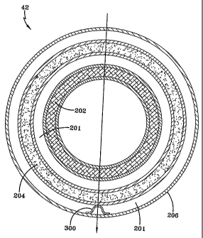
[0019] Figure 2 illustrates a longitudinal cross sectional view of an
embodiment of the
coalescing element of the present invention.
[0020] Figure 3 illustrates a coalescing element with one embodiment of the
drainage
arrangement of the present invention.
[0021] Figures 4-10 illustrate a coalescing element with several different
embodiments of a
drainage arrangement of the present invention.
[0022] Figures 11 and 12 illustrate performance data of the coalescing element
with the
drainage arrangement of Figure 4.
[0023] Wherever possible, the same reference numbers will be used throughout
the drawings
to refer to the same or like parts.
DETAILED DESCRIPTION OF THE INVENTION
[0024] Figure 1 illustrates an embodiment of a compression system that can
incorporate the
present invention. The compression system 2 includes a compressor 10, a motor
20, and a
separator arrangement 30. The compressor 10 and motor 20 can be integrally
mounted with the
separator arrangement 30 or alternatively, the compressor 10, motor 20 and
separator
arrangement 30 can be separately mounted. The compressor 10 operates to
compress a gas from
a lower pressure to a higher pressure. The compressed gas can include
entrained lubricant
having a random size distribution. The droplet size of the lubricant can vary
from greater than
1000 microns to submicron. The compressed gas and entrained lubricant exits
the compressor
at a discharge port 12 where it is carried by conduit 22 into the separator
arrangement 30.
[0025] In a preferred einbodiinent, the separator arrangement 30 is a
horizontal separator in
which the compressed fluid moves substantially axially (i.e., horizontally)
through the separator
arrangement 30. In another embodiment, a vertical separator arrangement may
also be used.
The separator arrangeinent 30 can include a shell 15 having a first head 32, a
second head 34,
and a discharge port 36. The separator arrangement 30 preferably has three
stages, a first stage
23 where the direction of the fluid is changed, a second stage 25 where
droplets are removed
-5-
CA 02617177 2008-01-29
WO 2007/019127 PCT/US2006/029847
from the fluid streanz and a third stage 27. In addition, the second head 34
can include a
manway 48 or headway that provides ready access to components in the third
stage 27.
[0026] Compressed gas with entrained lubricant traveling at high velocity
enters the first
stage 23 of the separator arrangement 30 through conduit 22. In this first
stage 23, the
compressed gas expands on exiting the conduit 22, experiencing a velocity
drop. The
compressed gas and entrained lubricant then strike a barrier, i.e., the first
head 32, and undergo a
direction change. A portion of the entrained lubricant, e.g., the larger
droplets or agglomerated
smaller droplets resulting from contact with first head 32, separate as liquid
into a bottom portion
38 of the shell 15. This occurs as the droplets reach a critical size such
that gravity draws these
larger droplets from the fluid stream. A substantial portion of the remaining
entrained lubricant is
smaller than this critical droplet size and remains in the fluid stream. In
the first stage 23,
droplets and/or particles of about 70 microns or larger are agglomerated and
substantially
removed by gravity. The remaining fluid leaving the first stage 23 includes
droplets entrained in
the compressed gas as a combination of fine aerosol and a fine mist. The mist
includes droplets
having a size distribution with a diameter in the range above about 1.0 micron
to about 70
microns, with a very large number of particles in the submicron, or aerosol,
range. The
agglomerated lubricant from the first stage 23 may include a small amount of
dissolved
refrigerant. The liquid that drops to the bottom portion or sump 38 of shell
15 acts as a main oil
reservoir and is returned to compressor 10, where it lubricates the bearings
and other moving
parts of the compressor 10. This lubricant is filtered and cooled before
returning to the main
compressor, which return may be accomplished by an additional component, e.g.,
a pump, in
some systems.
[0027] The fluid then moves into the second stage 25 of the separator
arrangement 30 to
remove additional lubricant droplets from the compressed gas. A number of
options are
available for this stage, each of the options removing droplets of different
sizes. One option is to
utilize the length of the shell 15 to remove droplets as the compressed gas
travels along the
length of the shell 15. This option is of limited value in a shell 15 of
relatively short length. A
second option utilizes a plate pack (not shown) in which the compressed gas
and entrained
lubricant passes over a series of stationary plates. Lubricant droplets having
a size in the range
of about 15 microns to about 700 microns are reinoved from the streain in this
option,
-6-
CA 02617177 2008-01-29
WO 2007/019127 PCT/US2006/029847
agglomerating on the plates as the fluid passes over the plates. A few smaller
particles and a few
remaining larger particles may also agglomerate on the plates. Another option
shown in Figure 1
utilizes a mesh pad 29, typically a large metallic mesh structure through
which the compressed
gas passes. As the compressed gas with the entrained lubricant contacts the
mesh structure of the
mesh pad 29, liquid droplets agglomerate on the mesh structure. Mesh pads
typically remove
droplets in the range of about 5 microns and larger, leaving only droplets in
a very fine mist or
aerosol range. Regardless of the structure selected for the second stage 25,
the agglomerated
lubricant drops to the sump 38 with the lubricant removed in the first stage
23.
[0028] The fluid leaving the second stage 25 in the form of a compressed gas
having
entrained mist and aerosol then moves into the third stage 27 of the separator
arrangement 30.
The third stage 27 can include a coalescer portion 40. The coalescer portion
40 can include at
least one filter, and typically a series of filters of progressively finer
mesh in the fonn of fibers.
In a preferred embodiment of the present invention, these filters are
incorporated into one or
more coalescing elements 42. The coalescing element 42 preferably has a
substantially
cylindrical shape, although any suitable shape can be used. The coalescer
portion 40 also
includes a coalescer reservoir 44, a return line 46 from the coalescer
reservoir 44 to compressor
and a manway 48 to provide access to the coalescer portion 40. Discharge port
36 of
separator 30 is located in the coalescer portion 40 downstream of the one or
more coalescing
elements 42.
[0029] The purpose of the coalescer portion 40, and specifically the one or
more coalescing
elements 42, is to remove as much of the remaining lubricant from the
compressed gas as
possible, so that the lubricant can be returned to the compressor 10 to
perform its lubricating
function, and the compressed gas can pass downstream of the separator
arrangement 30, e.g.,
into a condenser of an HVAC system or into a storage container of a natural
gas system, with as
little entrained lubricant as possible. Thus, the coalescing element 42 has to
remove the
remaining mist and as much of the aerosol as possible from the compressed
fluid before it leaves
the separator arrangement 30. As the gas with entrained mist and aerosol pass
into the coalescer
portion 40, the mist-like particles form droplets on the filter(s) of the
coalescing element 42 and
drop into coalescer reservoir 44. The filter or series of filters in the
coalescing element 42 are
comprised of fine mesh fibers, sucli as glass microfibers. These microfibers
have sufficient
-7-
CA 02617177 2008-01-29
WO 2007/019127 PCT/US2006/029847
surface area to drop the velocity of the gas and mist passing through it
sufficiently so that the
filters are effective to coalesce the mist into droplets that fall to the
coalescer reservoir 44 as a
liquid.
[0030] Once the compressed gas has passed through the at least one filter of
the coalescing
element 42, the gas exits the separator arrangement 30 through discharge port
36 into a conduit
for transference downstream for subsequent processing. The liquid agglomerated
into coalescer
reservoir 44, which is substantially lubricant but may include a small amount
of dissolved
refrigerant, is returned via return line 46 to the compressor 10 after
filtering. Because the
coalescer reservoir 44 is the low pressure point of the separator arrangement
30, yet on the high
pressure side of the system, the lubricant in the coalescer reservoir 44,
being at a higher pressure
than the pressure on the low pressure side (suction side) of the compressor
10, is returned by this
pressure differential to compressor 10 where the lubricant is used to
lubricate and seal moving
parts of the compressor 10.
[0031] Figure 2 illustrates one embodiment of the coalescing element 42 of the
present
invention. As shown in Figures 1 and 2, the coalescing element 42 is
preferably horizontally
mounted, but in other embodiments of the present invention, the coalescing
element 42 can be
vertically mounted. As discussed above, the coalescing element 42 is used to
remove entrained
lubricant in a mist or aerosol form from the gas flow before the gas exits the
separator
arrangement 30. The gas and entrained lubricant enters the coalescing element
42 from the
second stage 25 at an inlet 200 located at one end of the coalescing element
42. The other end of
the coalescing element 42 is sealed or closed, preferably as a result of
mounting the coalescing
element 42 in the coalescer portion 40. The sealing or closing of the end of
the coalescing
element 42 opposite the inlet 200 forces the gas and entrained lubricant to
exit the coalescing
element 42 through the sides of the coalescing element 42.
[0032] After entering the inlet 200 of the coalescing element 42, the gas
passes through a
first filter element 202, a second filter element 204 and an outer mesh or
screen member 206.
The first filter element 202, the second filter element 204 and the outer mesh
or screen meinber
206 are substantially coaxial to one another and separated by air gaps 201.
The first filter
element 202 and the second filter element 204 are used to remove any entrained
lubricant from
-8-
CA 02617177 2008-01-29
WO 2007/019127 PCT/US2006/029847
the gas flow. The outer mesh or screen member 206 is preferably a perforated
metal or expanded
metal used to strengthen the coalescing element 42 and to assist in the
drainage of the coalesced
lubricant from the coalescing element 42. It is to be understood that while
Figure 2 shows the
first filter element 202 and the second filter element 204, any desired number
of filter elements
can be used, including only one filter element or more than two filter
elements.
[0033] Each of the first filter element 202 and the second filter element 204
have a
substantially cylindrical shape and include a filter media surrounded by a
mesh or screen
member on each side to contain the filter media. The filter media can be held
in the cylindrical
shape by any suitable technique including adhesives. Similarly, the mesh or
screen members can
be held in the cylindrical shape by any suitable technique. Preferably, the
inner mesh or screen
member surrounding the filter media is perforated metal or expanded metal and
the outer mesh
or screen member surrounding the filter media is a wire mesh. However, in
other embodiments
both the inner and outer mesh or screen member can be the same type, i.e.,
both perforated metal,
both expanded metal or both wire mesh. In still additional embodiments, the
inner mesh or
screen member surrounding the filter media is a wire mesh and the outer mesh
or screen member
surrounding the filter media is perforated metal or expanded metal.
[0034] The filter media of both the first filter element 202 and the second
filter element 204
can be a fine material fiber or microfiber material, such as fiberglass, which
causes the remaining
mist and aerosol lubricant to coalesce into droplets on or in the filter
media, after which, by
gravity, the droplets fall into a coalescer reservoir 44. In another
embodiment of the present
invention, the filter media can be in a pleated or convoluted arrangement
instead of a fibrous
arrangement. Furthermore, the specific arrangement of the filter media can be
selected based on
desired performance characteristics and the ability to withstand operating
conditions. In a
preferred embodiment, the filter media in the first filter element 202 is a
"roughing" filter media
and the filter media in the second filter element 204 is "finish" filter
media.
[0035] As discussed above, the lubricant coalesces on the filter media of the
first filter
element 202 and the second filter element 204. The coalesced lubricant can
accumulate in the
filter media, thereby reducing the amount of available filter media that can
be used to coalesce
lubricant from the gas streain. To remove this accuinulated coalesced
lubricant, a drainage
-9-
CA 02617177 2008-01-29
WO 2007/019127 PCT/US2006/029847
mechanism is located in the air gaps 201 between the second filter element 204
and the outer
screen 206 and/or between the first filter element 202 and the second filter
element 204. In other
embodiments having additional filter elements, the drainage mechanism can be
located in the
corresponding air gaps between filter elements. The drainage mechanism is
located in the lower
half and preferably at the bottom of the coalescing element 42, i.e., the "6
o' clock position"
when mounted horizontally, and is in contact with the corresponding filter
element with which
the drainage mechanism is draining. The drainage mechanism is preferably a
single member or
piece that extends along the entire length of the coalescing element 42.
However, in other
embodiments, the drainage mechanism can include more than one member or piece,
arranged
either radially, longitudinally, or both. The drainage mechanism operates to
drain or wick the
accumulated lubricant out of the filter media and into the coalescer reservoir
44. Specifically,
the drainage mechanism operates to remove or drain liquid from the filter
media by reducing the
surface tension along the line of contact between the filter media and the
drainage mechanism.
By draining the accumulated lubricant out of the filter media, the drainage
mechanism reduces
the saturation zone of the filter media and increases the available amount of
filter media for
coalescing lubricant out of the gas stream. The drainage mechanism can have
any desired shape
that maintains contact with the filter element including the filter media and
can drain away the
accumulated lubricant. Further, the drainage mechanism can be made of any
suitable material
including metals, rubber or plastic materials.
[0036] Figure 3 illustrates a preferred embodiment of the drainage mechanism.
The drainage
mechanism is preferably a drainage meinber 300 having a horseshoe, arch or
inverted U shape
with a curved or arced portion in contact with the second filter element 204
that extends to the
outer screen or mesh element 206. The contact of the drainage member 300 with
the second
filter member 204 drains or wicks the accumulated lubricant out of the second
filter element 204,
which then flows down the sides of the drainage ineinber 300 and out of the
outer screen 206 to
the coalescer reservoir 44.
[0037] Figures 4-10 illustrate different einbodiments of the drainage
mechanism of the
present invention. Figure 4 is similar to Figure 3 in using the drainage
member 300. However,
Figure 4 also shows a second ineinber 400 disposed in the air gap 201 between
the outer screen
member 206 and the second filter ineinber 204 opposite the drainage member
300. While the
-10-
CA 02617177 2008-01-29
WO 2007/019127 PCT/US2006/029847
second member 400 may have a shape similar to drainage member 300, the second
member 400
does not operate to remove any accumulated lubricant from the second filter
member 204. The
second member 400 is primarily used to provide support to the coalescing
element 42 during the
manufacturing process.
[0038] Figure 5 is also similar to Figure 3 except that multiple drainage
members 300 are
used instead of the one drainage member 300 from Figure 3. The multiple
drainage members
300 can be formed into a single piece or they can be inserted as individual
pieces. To help with
the drainage of the accumulated lubricant in this embodiment, there can be
preferably one or
more holes extending along the length of the ends or portions of adjacent
drainage members 300
that are adjacent to the outer screen member 206 to drain lubricant.
Alternatively, the drainage
members 300 can be arranged so that there is adequate drainage space between
the drainage
members 300.
[0039] Figure 6 is also similar to Figure 3 except that a drainage member 600
is used instead
of the drainage member 300 from Figure 3. The drainage member 600 is
preferably a strip of
rubber or plastic material, such as an 0-ring or Teflon strip, having rounded
edges. Figure 7
shows multiple drainage members 600 between the second filter element 204 and
the outer
screen member 206 and also includes an additional drainage member 700 located
between the
first filter element 202 and the second filter element 204. The additional
drainage member 700
can be made of the same material as drainage member 600, but can also be made
of a different
material. The additional drainage member 700 operates to remove accumulated
lubricant from
the first filter element 202 and the multiple drainage elements 600 operate to
remove the
accumulated lubricant from the second filter element 204.
[0040] Figures 8-10 illustrate another embodiment of the drainage mechanism of
the present
invention. The drainage mechanism in this embodiment is formed by indenting a
portion of the
outer screen 206 to contact the second filter element 204. The indented
portion 800 of the outer
screen 206 operates in a similar manner to the drainage elements 300 and 600.
As shown in
Figures 9 and 10, one or more additional drainage members 700 can be used with
the indented
portion 800. In still another embodiment, more than one indented portion can
be used as a
drainage mechanism.
-11-
CA 02617177 2008-01-29
WO 2007/019127 PCT/US2006/029847
[0041] Figures 11 and 12 show performance data of the coalescing element of
the present
invention. For the evaluations shown in Figures 11 and 12, the same
compression system 2
using the same refrigerant and operating under the same conditions, e.g.,
temperature and
pressure, was used. Figure 11 shows a comparison of the remaining entrained
lubricant after
passing through the coalescer portion 40. The "baseline" measurements were
taken with a
coalescing element not having a drainage mechanism and the "new" measurements
were taken
with a similar coalescing element arranged according to Figure 4, including
drainage member
300. As can be seen in Figure 11, less oil remained in the gas flow when using
the embodiment
of the coalescing element from Figure 4.
[0042] Figure 12 shows a comparison of the pressure drop of the gas flow
through the
coalescer portion 40. The "baseline" measurements were taken with a coalescing
element not
having a drainage mechanism and the "new" measurements were taken with a
similar coalescing
element arranged according to Figure 4, including drainage member 300. As can
be seen in
Figure 12, the pressure drop of the gas through the coalescer portion 40 was
lower when using
the embodiment of the coalescing element from Figure 4. This reduction in
pressure drop
equates to a reduction in the power consumption of the compression system 2.
Finally, it is to be
understood that the test results shown in Figures 11 and 12 were for a
specific system and that
the incorporation of the coalescing element 42 into different systems may
result in different test
results.
[0043] In one embodiment of the present invention, the compression system 2
can be
incorporated in a heating, ventilation, and air conditioning (HVAC),
refrigeration or liquid
chiller system. In addition to the compressor 10, the system also includes a
condenser, an
expansion device and a water chiller or evaporator. Compressor 10 coinpresses
a refrigerant
vapor and delivers the vapor to the condenser, after passing through the
separator arrangement
30, using discharge port 36. The refrigerant vapor delivered to the condenser
enters into a heat
exchange relationship with a fluid, e.g., air or water, and undergoes a phase
change to a
refrigerant liquid as a result of the heat exchange relationship with the
fluid. The condensed
liquid refrigerant from the condenser flows to the evaporator after passing
tllrough the expansion
device. The liquid refi-igerant with possibly some vapor refrigerant enters
the evaporator and
enters into a heat exchange relationship with a fluid, e.g., air or water, and
undergoes a phase
-12-
CA 02617177 2008-01-29
WO 2007/019127 PCT/US2006/029847
change to a refrigerant vapor as a result of the heat exchange relationship
with the fluid. The
vapor refrigerant in the evaporator exits the evaporator and returns to the
compressor 10 by a
suction line to complete the cycle.
[0044] The compression system 2 includes a motor or drive mechanism 20 to
drive the
compressor 10. While the term "motor" is used with respect to the drive
mechanism for the
compressor 10, it is to be understood that the term "motor" is not limited to
a motor, but is
intended to encompass any component that can be used in conjunction with the
driving of motor
10, such as a variable speed drive and a motor starter. In a preferred
embodiment of the present
invention, the motor or drive mechanism 20 is an electric motor and associated
components.
However, other drive mechanisms, such as steam or gas turbines or engines and
associated
components can be used to drive the compressor 10.
[0045] While the invention has been described with reference to a preferred
embodimerit, it
will be understood by those skilled in the art that various changes may be
made and equivalents
may be substituted for elements thereof without departing from the scope of
the invention. In
addition, many modifications may be made to adapt a particular situation or
material to the
teachings of the invention without departing from the essential scope thereof.
Therefore, it is
intended that the invention not be limited to the particular embodiment
disclosed as the best
mode contemplated for carrying out this invention, but that the invention will
include all
embodiments falling within the scope of the appended claims.
-13-