Note: Descriptions are shown in the official language in which they were submitted.
CA 02617412 2008-01-30
WO 2007/024284 PCT/US2006/014635
CABLE AND CABLE CONNECTION ASSEMBLY
FIELD OF THE INVENTION
The illustrated embodiments of the present invention relate generally to cable
connection assemblies, and more specifically, to cable connection assemblies
for
connecting a first length of cable to an apparatus, such as a second length of
cable a dead
end seal.
BACKGROUND OF THE INVENTION
Often, a need arises to splice a first length of cable to a second length of
cable of a
cable assembly. Cable connection assemblies have been developed to meet this
need.
For instance, referring to FIGURE 1, one previously developed cable connection
assembly 10 for connecting a first length of cable 11 to a second length of
cable 13 of a
cable assembly is shown. The cable connection assembly 10 includes a crimp
connector 16 which is crimped to couple a first conductor 12 of the first
cable 11 to a
second conductor 14 of the second cable 13. The first and second conductors 12
and 14
each pass coaxially through an insulative conduit 18 and 20 of the first and
second
cables 11 and 13. The insulative conduits 18 and 20 each slidingly pass
through a
connection collar 22 and 24, respectively. The connection collars 22 and 24
include
threaded portions 26 and 28. The threaded portions 26 and 28 are adapted to
interface
with a pair of threaded portions 30 and 32 disposed on a sleeve 34 which is a
hollow,
cylindrical member machined so as to have a variable wall thiclcness and the
threaded
portions 30 and 32.
The cable connection assembly 10 also includes a pair of seal assemblies 36
and 38. Each seal assembly 36 and 38 includes a pair of annular shaped washers
40 and a
compression seal 42. As the pair -of washers 40 are pressed toward one
another, the
compression seal 42 disposed between the washers 40 expands outward to
sealingly
engage the sleeve 34 and inward to sealingly engage the outer surface of the
insulative
conduit 18 and 20. To force the pair of washers 40 toward one another, each of
the
collars 22 and 24 include a shoulder 44 and each end of the sleeve 34 includes
a
shoulder 46. As the collars 22 and 24 are tlireaded onto the sleeve 34, the
opposing
shoulders 44 and 46 force the washers 40 towards one another, forcing the
compression
seal 42 in sealing relationship with the sleeve 34 and the insulative conduits
18 and 20.
-1-
CA 02617412 2008-01-30
WO 2007/024284 PCT/US2006/014635
Of note, although not shown, the connection assembly 10 may be wrapped/encased
with
an insulation layer as is well known to those skilled in the art.
Although this cable connection assembly 10 is effective, it is not without its
problems. For instance, each cable connection assembly 10 must be custom
designed for
each cable to be spliced. Moreover, for the seal assemblies 36 and 38 to
properly seal
against the outer surfaces of the insulative conduits 18 and 20, the exact
diam.eter of the
insulative conduits 18 and 20 must be known so that the parts of the cable
connection
assembly 10 can be designed accordingly such that the seal asseinblies 36 and
38 are able
to seal properly against the insulative conduits 18 and 20 and the sleeve 34.
The custom designing of the cable connection assembly 10 for each application
increases the cost of the cable connection assembly 10 and causes a delay in
how fast a
proper cable connection assembly 10 can be provided to the end user. Further,
the cable
connection asseinbly 10 is difficult to asseinble due in part to the large
number of parts,
the inability of the sleeve 34 to slide over the collars 22 and 24, the fact
that the collars 22
and 24 have to be threaded into the sleeve 34, and due to the fact that the
proper ainount
of coinpression must be applied to the compression seals 42 for them to seal
properly.
Thus, there exists a need for an improved cable connection assembly that is
inexpensive to manufacture, reliable, easy to assemble, seals well, and/or
which can be
used with a wider range of conductor and/or insulation diameters.
SUMMARY OF THE INVENTION
One embodiment of a cable connection assembly formed in accordance with the
present invention for coupling a cable to an apparatus is disclosed. The cable
connection
assembly includes a collar adapted to sealingly engage the apparatus, the
collar having a
fastener for coupling the collar to the cable by rotating the collar into
locking engagement
with at least a portion of the cable.
Another embodiment of a cable connection assembly for a cable is disclosed.
The
cable connection assembly includes a collar having a collar fastener, wherein
the collar
fastener is adapted to couple to the cable by rotation of the collar fastener
relative to the
cable. The cable connection asseinbly also includes a sleeve adapted to
sealingly engage
the collar, thereby defining a cavity in which an end of the cable is adapted
to be at least
partially disposed within.
Still another embodiment of a cable connection assembly forined in accordance
with the present invention is disclosed. The cable connection assembly may be
used for
-2-
CA 02617412 2008-01-30
WO 2007/024284 PCT/US2006/014635
coupling a first conductor for carrying electrical current to a second
conductor for
carrying electrical current, the first conductor being insulated by a first
insulative conduit
having a first conduit fastener, the second conductor being insulated by a
second
insulative conduit having a second conduit fastener.
The cable connection assembly includes a first collar having an outer surface,
an
inner surface defining a passageway passing axially through the first collar
for permitting
the first conductor to pass therethrough, a first collar fastener adapted to
couple to the
first conduit fastener by rotation of the first collar fastener relative to
the first conduit
fastener, and a seal disposed on the outer surface.
The cable connection assembly also includes a second collar having an outer
surface, an inner surface defining a passageway passing axially through the
second collar
for permitting the second conductor to pass therethrough, a second collar
fastener adapted
to couple to the second conduit fastener by rotation of the second collar
fastener relative
to the second conduit fastener, and a seal disposed on the outer surface. The
cable
connection assembly further includes a sleeve having a passageway passing
therethrough,
the passageway adapted to at least partially receive the first and second
conductors, the
sleeve adapted to sealingly engage the seal disposed on the outer surface of
the first collar
and the seal disposed on the outer surface of the second collar.
One embodiment of a method performed in accordance with the present invention
for coupling a cable to an apparatus is disclosed. The method includes
rotating a collar
such that a fastener of the collar lockingly engages the cable and sealingly
coupling the
apparatus to the collar.
BRIEF DESCRIPTION OF THE DRAWINGS
The foregoing aspects and many of the attendant advantages of this invention
will
become better understood by reference to the following detailed description,
when taken
in conjunction with the accompanying drawings, wherein:
FIGURE 1 is a partial cross-sectional view of a previously developed cable
comlection assembly for coupling a first length of cable to a second length of
cable of a
cable assembly;
FIGURE 2 is a partial cross-sectional and exploded elevational view of one
embodiment of a cable connection assembly formed in accordance with the
present
invention for coupling a first length of cable to a second length of cable of
a cable
assembly;
-3-
CA 02617412 2008-01-30
WO 2007/024284 PCT/US2006/014635
FIGURE 3 is a partial cross-sectional view of the cable and cable connection
assembly of FIGURE 2 prior to assembly;
FIGURE 4 is a partial cross-sectional, assembled, elevational view of the
cable
and cable connection asseinbly of FIGURE 2;
FIGURE 5 is a partial cross-sectional, assembled, elevational view of an
alternate
embodiment of a cable connection assembly formed in accordance with the
present
invention for terminating an end of a cable;
FIGURE 6 is a partial cross-sectional and exploded elevational view of an
alternate embodiment of a cable comiection assembly formed in accordance with
the
present invention for coupling a first length of cable to a second length of
cable of a cable
assembly; and
FIGURE 7 is an elevation view of an electrical continuity connection assembly
used with the cable connection asseinbly of FIGURE 6.
DETAILED DESCRIPTION OF THE PREFERRED EMBODIMENT
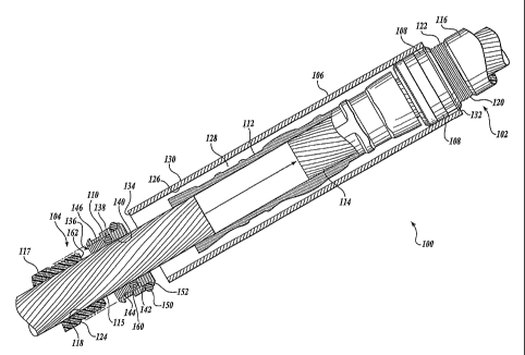
Referring to FIGURES 2-4, one embodiment of a cable connection assembly 100
formed in accordance with the present invention is shown. The cable comiection
assembly 100 may be used to couple a first cable 102 to a second cable 104 of
a cable
assembly. The cable connection assembly 100 may include a sleeve 106, a first
collar 108, a second collar 110, and a cable connector 112. These components
worlc
together to enable a user to splice the first cable 102 to the second cable
104 as shown in
FIGURE 4.
Turning to FIGURE 2, the first and second cables 102 and 104 of the cable
assembly are substantially identical to one another and each include a
conductor 114 and
115 for carrying a current and an insulative conduit 116 and 117 for
insulating the
conductor 114 and 115. In the illustrative embodiment, the conductors 114 and
115 are
helically wound, multi-strand wires, although it should be apparent to those
skilled in the
art that the conductors 114 and 115 may be of any suitable material and design
able to
efficiently carry a current, a few suitable examples being aluminum or copper
based solid
core or multi strand wires.
The insulative conduits 116 and 117 may be tubular shaped so as to have a
passageway 118 passing coaxially through the insulative conduit 116 or 117,
the
passageway 118 sized and shaped to receive the conductor 114 or 115. The
insulative
conduits 116 and 117 may each include a reduced diameter portion 120 having a
diameter
-4-
CA 02617412 2008-01-30
WO 2007/024284 PCT/US2006/014635
that is less than a normal diameter of the rest of the insulative conduit 116
and 117.
Disposed on the reduced diameter portion is a conduit fastener, which in the
illustrated
embodiment, is in the form of a set of external threads 122. A shoulder 124 is
formed as
the diameter of the insulative conduit 116 and 117 transitions from the normal
diameter
of the insulative conduit 116 and 117 to the reduced diameter portion 120. The
insulative
conduit 116 and 117 may be formed from any suitable insulative material hereto
known
or to be developed, a few suitable examples being high molecular weight
polyethylene
(HMWPE) and cross-linked polyethylene (XLPE).
The sleeve 106 may be an elongate hollow, tubular apparatus having an inner
surface 126 defining an internal cavity 128 and an outer surface 130 spaced
from the
inner surface 126 by a thickness of a wall of the sleeve 106. The ends 132 and
134 of the
sleeve 106 are open. The sleeve 106 is adapted to receive the free ends of the
first and
second conductors 114 and 115 within the internal cavity 128 of the sleeve 106
through
the open ends 132 and 134 of the sleeve 106. The sleeve 106 may be made from a
seamless pipe, and in one working embodiment, is made from seamless aluminum
pipe
able to withstand high pressures, such as above about 50 psi, or even higher
pressures,
such as above 70 psi, 90 psi, or 100 psi.
In one embodiment, the sleeve 106 is made from a pipe having a pipe wall of a
substantially constant tlzickness and diameter with smooth inner and outer
surfaces 126
and 130. Inasinuch as the sleeve 106 of this working embodiment may be formed
from
standard pipe which does not require further machining, such as to form
threads, recesses,
or variable wall thiclcnesses or diameters, the sleeve 106 may be easily
manufactured at a
low cost. Although the illustrated embodiment depicts the sleeve as being
formed from a
smooth wall pipe, it should be apparent that the sleeve 106 may alternately be
other than
round, have a varying wall thickness or diameter, recesses, threads, channels,
etc.,
without departing from the spirit and scope of the present invention.
Focusing now on the collars 108 and 110, the collars 108 and 110 are
substantially identical to one another. Therefore, for the sake of brevity,
only one of the
collars will be described in detail herein, those skilled in the art
appreciating that the
description of one of the collars applies equally well to the other collar.
The collar 110 is
annular in shape and includes a passageway 136 passing coaxially through the
collar 110.
The passageway 136 is sized and configured to permit the conductor 115 to pass
therethrough.
-5-
CA 02617412 2008-01-30
WO 2007/024284 PCT/US2006/014635
The passageway 136 includes an enlarged diameter section 138 and a reduced
diameter section 140, thereby forming a shoulder 142 as the inner surface of
the
passageway 136 transitions from the enlarged diameter to the reduced diameter.
Disposed on the enlarged diameter section 138 is a collar fastener, which in
the illustrated
embodiment is in the form of a set of internal threads 144. The internal
threads 144 are
sized and shaped to sealingly engage the external threads 122 of the
insulative
conduit 117.
. Disposed on the outer surface of the collar 110 is a recess 146. Turning to
FIGURE 4, the recess 146 is an annular channel disposed circuinferentially
about the
collar 110. The recess 146 is able to receive a deformed portion 148 of the
sleeve 106 to
aid in coupling of the sleeve 106 to the collar 110. For instance, the sleeve
106 may be
crimped at the location of the recess 146 to cause the sleeve 106 to deform
into the
recess 146.
Although a recess 146 is shown, it is noted that the recess 146 may be removed
from the collar 110 without departing from the spirit and scope of the present
invention.
Further, although a recess 146 is shown and described for coupling the sleeve
106 to the
collar 110, it should be apparent to those skilled in the art that the sleeve
106, if desired to
be mechanically coupled to the collar 110, may be coupled to the collar 110 in
any
number of ways other than deforming the sleeve 106 into the recess 146, a few
suitable
examples being adliesives, welding, and mechanical fasteners, such as set
screws.
Returning to FIGURE 2, the outer surface of the collar 110 includes a seal
150.
The seal 150 is sized and shaped to sealingly engage both the collar 110 and
the
sleeve 106 to provide a pressure seal between the collar 110 and the sleeve
106. Thus,
the sleeve 106 forms a pressure vessel able to contain a fluid under pressure
within the
sleeve 106. For instance, when a restorative compound is pumped into the cable
102, the
sleeve 106 seals the first cable 102 to the second cable 104 while permitting
restorative
compound to pass between the cables and the sleeve 106 also assists in
resisting moisture
transfer from entering the conductor area.
In the illustrated embodiment, the seal 150 is an 0-ring disposed witliin an
annular channel 152 located circuinferentially about the collar 110. Although
the
seal 150 is illustrated and described as being an 0-ring disposed within a
channel, it
should be apparent that the seal may take otlier forms without departing from
the scope of
-6-
CA 02617412 2008-01-30
WO 2007/024284 PCT/US2006/014635
the present invention. For example, a gasket type seal or a liquid applied
sealant used
with or without a channel are within the scope of the present invention.
The cable connection assembly 100 includes a conduit end seal 160. The conduit
end seal 160 is adapted to seal the collar 110 to the insulative conduit 117.
For instance,
the conduit end seal 160 is adapted to sealing engage an end surface 162 of
the insulative
conduit 117 and the shoulder 142 of the collar 110, thereby sealing the
insulative
conduit 117 to the collar 110. Thus, when a restorative coinpound or other
fluid is
injected along the length of the conductor 115, the fluid will flow through
the collar 110
without leaking at the connection between collar 110 and the insulative
conduit 117,
should the threaded connection between the collar 110 and the insulative
conduit 117
prove inadequate to seal the fluid therewithin.
Although the illustrated einbodiment depicts the conduit end seal 160 as an 0-
ring, those skilled in the art will appreciate that the conduit end seal 160
may take ina.ny
forms, including compression gaskets and/or liquid applied gaskets.
The cable connector 112 is used to both physically and electrically couple the
two
conductors 114 and 115. Specifically, the connector 112 is a crimp style
connector, made
of an electrically conductive material that is sufficiently malleable to
permit the
connector 112 to be crimped to couple the two conductors 114 and 115 together.
The
connector 112 perinits culTent from one conductor 114 to pass to the other
connector 115
and couple the two conductors 114 and 115 together to withstand a
predetermined tensile
force.
Althougll a crimp style connector 112 is illustrated and described, it should
be
apparent to those skilled in the art that other types of connectors 112 are
within the scope
of the present invention. A few suitable examples being connectors 112 which
do not
provide any substantial mechanical connection between the two conductors 114
and 115,
a tube style connector utilizing set screws for coupling the connector to the
conductors,
etc. Of note, FIGURE 3 shows the connector 112 prior to being crimped. FIGURES
2
and 4 show the connector 112 after crimping.
In light of the above description, the installation and use of the cable
connection
assembly .100 will now be described in greater detail. Referring to FIGURE 3,
in the area
of the splice, the insulative conduits 116 and 117 are cut back a
predetermined distance
from the free ends of the conductors 114 and 115. The reduced diameter portion
of the
insulative conduits 116 and 117 is cut into the insulative conduits 116 and
117 and
-7-
CA 02617412 2008-01-30
WO 2007/024284 PCT/US2006/014635
threaded so as to have external threads 122. The seal 150 is pushed over the
reduced
diameter portion 120 of the collar 110. The internal threads 144 of the
collars 108 and
110 are screwed onto the external threads 122 of the insulative conduits 116
and 117 by
rotation of the collars 108 and 110 relative to the insulative conduits 116
and 117. The
sleeve 106 is then slid past one of the collars, such as collar 110. This is
made easier
since the seal 150 associated with collar 110 is disposed on the reduced
diameter
portion 120 of the insulative conduit 117 instead of upon the collar 110.
The free ends of the conductors 114 and 115 are then inserted within the cable
connector 112 in an end to end relationship. The connector 112 is then crimped
as is well
known in the art to both electrically and mechanically couple the two
conductors 114 and
115 to one another, also resulting in a fluid tight seal. The sleeve 106 is
then slid back
over the collar 110 and past the collar 110 such that the seal 150 can be
placed in the
channel 152 of collar 110. The sleeve 106 is then moved such that sleeve 106
sealingly
engages the seal 150 associated with the first collar 108 and the seal 150
associated with
the second collar 110, thereby forming a pressure vessel housing the connector
112.
The pressure vessel formed is able to withstand fluid pressures to impede a
fluid,
such as restorative compound, from leaking from the connection assembly 100,
or a fluid,
such as water, from entering the connection asseinbly 100. Preferably, the
connection
assembly is able to withstand fluid pressures of greater tha.n 25 psi, or even
higher
pressures such as greater than 50 psi, 75 psi, or 100 psi. The sleeve 106 may
then be
deformed, such as by crimping, such that the deformed portions 148 (See FIGURE
4) of
the sleeve 106 enter the recess 146 in the collars 108 and 110, thereby
mechanically
coupling the sleeve 106 to the collars 108 and 110.
The first and second collars 108 and 110 are threaded to the insulative
conduits 116 and 117, thereby creating an end seal between the end surface 162
and the
shoulder 142. Further, because of the threaded engagement between the collars
108
and 110 and the insulative conduits 116 and 117, the resulting attachment is
more secure
than existing designs. Specifically, the seal between the end surface 162 and
the
shoulder 142 is maintained during dynamic changes, such as thermal changes, in
the
insulative conduits. Because the collars 108 and 110 are threadably coiuiected
to the
insulative conduits 116 and 117, any changes or nlovenlent of the insulative
conduits
results in a corresponding movement of the collar. This maintains a secure end
seal
between the end surface 162 and the shoulder 142.
-8-
CA 02617412 2008-01-30
WO 2007/024284 PCT/US2006/014635
As is apparent to those skilled in the art based on the above description, the
illustrated embodiment of the cable connection assembly 100 is able to be used
with
many different sizes of cables having varying conductor and insulative conduit
diameters.
Moreover, since the insulative conduits are cut after manufacture to form the
reduced
diameter portion 120 with the external threads 122, the outer diameter of the
insulative
conduit is relatively unimportant since the seal between the collar and the
insulative
conduit is formed at the reduced diameter portion 120 having a predetermined
diameter
formed when the reduced diameter portion is cut into the insulative conduit,
and not on
the outer surface of the conduit which can have a diameter that varies between
different
cables. Thus, for the illustrated embodiment of the cable connection assembly
100, the
cable comiection assembly 100 does not have to be custom designed based on the
exact
outer diameter of the insulative conduit.
Referring to FIGURE 5, an alternate embodiment formed in accordance with the
present invention of a cable connection assembly 200 for terminating an end of
a
cable 204 of a cable assembly is shown. The cable connection assembly 200 is
substantially identical in construction and operation to the cable connection
assembly 100
of FIGURES 2-4, therefore this detailed description will, for the sake of
brevity, only
describe the aspects of the cable connection assembly 200 which depart from
the
previously described embodiment.
The cable connection assembly 200 of FIGURE 5 is used for terminating or dead
ending a cable 204 of a cable assembly. The cable 204 is identical to the
cable 104 of the
previously described embodiment. Likewise, the collar 210 is identical to the
collar 110
of the previously described einbodiinent. However, unlike the above the
described
embodiment, the sleeve 206 of the cable connection assembly 200 of FIGURE 5
includes
an end plate 207 for sealing off the distal end of the sleeve 206, the sleeve
206 thereby
acting as a dead end seal. Additionally, the sleeve 206 may include a
connector 209 for
permitting a fluid to be puinped into the sleeve 206. For instance, a user may
pump a
restorative compound into the sleeve 206 for restoring the insulative
properties of the
insulative conduit 217. The sleeve 206 sealingly engages the collar 210 to
form a
pressure vessel, the pressure vessel able to impede fluids from exiting or
entering the
cable connection assembly 200.
Although FIGURE 5 shows a sleeve in the form of a dead end seal having a
particular shape and form, it should be apparent to those skilled in the art
that the
-9-
CA 02617412 2008-01-30
WO 2007/024284 PCT/US2006/014635
illustrated dead end seal is illustrative in nature only and is not limiting.
Moreover, the
dead end seal shown is merely one example of a dead end seal suitable for use
with the
present invention, and those skilled in the art will appreciate that the dead
end seal may
take many different shapes and forms other than those illustrated and
described without
departing from the spirit and scope of the present invention.
Although the illustrated embodiment depicts and describes the collar and
conduit
fasteners as being threaded fasteners able to couple to one another by
rotation of the
collar fastener relative to the conduit fastener, it should be apparent that
other collar and
conduit fasteners are suitable for use with the present invention, a few
exalnples being
quick connect fasteners and bayonet type fasteners, which may or may not
require
rotation of the collar and conduit fasteners relative to one another to couple
to one
another.
Referring to FIGURE 6, a partial cross-sectional and exploded elevational view
of
an alternate embodiment of a cable connection assembly 300 formed in
accordance with
the present invention for coupling a first length of cable 302 to a second
length of
cable 304 of a cable assembly is illustrated and described. The cable
connection
assembly 300 is substantially similar to the cable comiection assenibly 100
illustrated and
described with respect to FIGURES 2-4. Therefore, for the sake of brevity,
this detailed
description will focus on the aspects of the cable connection assembly 300
which depart
from that previously described. More specifically, the cable connection
assembly 300
departs from the previously described embodiments in that the collars 308 and
310 of the
cable connection assembly 300 each include a fastening assembly 400 for
coupling the
collars 308 and 310 directly to the conductors 314 and 315. Further, the each
of the
collars 308 and 310 include an electrical continuity comlection assembly 500
for coupling
the collars 308 and 310 in electrical continuity with the splice body 306.
Focusing on the fastening assembly 400 of each collar 308 and 310, the
fastening
assembly 400 includes one or more fasteners 402 for coupling the collar 308 or
310
directly to the conductor 114 or 115. In the illustrated einbodiment, the
fasteners 402
include one or more set screws equally spaced about a circumference of the
collar 308
and 310 and radially oriented. Selectively rotating the set screws causes the
set screws to
move radially inward to engage and lock the collar 308 or 310 to the conductor
114 or
115. The fastening assembly 400 ensures a positive electrical connection
between the
collars 308 and 310 and the conductors 114 and 115. Additionally, the
fastening
-10-
CA 02617412 2008-01-30
WO 2007/024284 PCT/US2006/014635
assembly 400 retains the position of the collars 308 and 310 relative to the
ends of the
insulative conduits 116 and 117, thereby ensuring that the end seals 360
remain
compressed and in a sealing relationship with the collars 308 and 310 and the
end
surfaces 362 of the insulative conduits 116 and 117.
As mentioned above, the electrical continuity connection assembly 500 may be
used for coupling the collars 308 and 310 in electrical continuity with the
sleeve 306.
The electrical connection assembly 500 may include a retaining device 502 and
an
electrical connection device 504. The retaining device 502 in the illustrated
einbodiment
is a snap ring formed from a piece of wire formed in a circular shape. The
snap ring may
be spread and placed about the collar 308 or 310 and preferably set within a
cllannel 506
circumferentially disposed about the collar 308 or 310. Once placed in the
channel 506,
the snap ring attempts to conform to its original, non-spread shape, thereby
retaining the
snap ring within the channel 506.
Disposed about at least a portion of the retaining device 502 is the
electrical
connection device 504, which in the illustrated embodiment is a spring. The
diameter of
the spring may be selected such that when splice body 306 is installed over
the collar 308
or 310, the spring is compressed against both the splice body 306 and the
collar 308 or
310, ensuring an electrical connection between the two. Although the
illustrated
embodiment is illustrated and described with an electrical continuity
connection
assembly 500 which includes a snap ring and a spring, those skilled in the art
will
appreciate that the electrical continuity coimection assembly 500 may take
many other
forms suitable for use with and which are within the scope of the present
invention. For
instance, the electrical continuity connection assembly 500 may include an
endless
circular spring which is stretched and released in the channel 506. The
diameter of the
spring may be selected such that when the splice body 306 is installed over
the collar 308
or 310, the spring is compressed against both the splice body 306 and the
collar 308 or
310, ensuring an electrical connection between the two. In another example,
fasteners
may be used to ensure an electrical connection between the two.
While the preferred embodiment of the invention has been illustrated and
described, it will be appreciated that various changes can be made therein
without
departing from the spirit and scope of the invention.
-11-