Note: Descriptions are shown in the official language in which they were submitted.
CA 02617545 2008-01-31
WO 2007/019391 PCT/US2006/030614
APPARATUS FOR TREATING SPINAL STENOSIS
TECHNICAL FIELD
[0001] The present invention relates to an apparatus and method for
stabilizing the
human spine and, more specifically, to an implant for insertion between
adjacent vertebrae.
BACKGROUND
[0002] A human vertebrae has a rearwardly projecting portion lcnown as a
spinous
process. Bending of the spine can cause the spinous processes of adjacent
vertebrae to be
moved toward each other. This constricts the space in the spinal canal and
foramina and,
thus, may cause pain. Such constriction, which is known as stenosis, can be
treated by the
use of an implant in the space between adjacent spinous processes.
[0003] Some current implants are made of separate pieces which require
insertion
from opposite sides of the spine and in a posterior approach necessitate
ratller wide openings
into a patient, cutting both left and right tlzoracolumbar fascia as well as
stripping the
multifidus inuscles from their attachnients. It is desirable to provide an
implant for insertion
between the spinous processes of adjacent vertebrae which can be inserted
through a single
opening in a minimal invasive approach and may be held firmly in position
between the
vertebrae.
SUMMARY
[0004] The device of the present invention may include a body portion having a
first
end portion, a second end portion and a sleeve which may be positioned between
the first and
second end portions. The device may be sized and configured to fit between the
spinous
processes of two adjacent vertebrae. The sleeve may be a single piece of
material or may
comprise multiple components which may be made of materials having different
properties
(e.g., different modulus of elasticity). The device may have at least two
retainers, which may
be positioned within the body portion and may move between a deployed position
and a
CA 02617545 2008-01-31
WO 2007/019391 PCT/US2006/030614
retracted position. The device may also have a connector which may join the
first and second
end portions.
[0005] An actuation tool (e.g., a screwdriver) may be used to rotate the
connector.
Rotation of the connector may move the first and second end portions towards
each other. As
the first and second end portions are moved toward each other, the retainers
may be deployed
from the device. In the deployed position, the retainers may extend outward
from the body
portion and may be positioned on opposite sides of at least one spinous
process of a
vertebrae. In a preferred embodiment, the device may have four retainers for
engaging
opposite sides of two spinous processes of adjacent vertebrae. Such retainers
may hold the
implant in position relative to the spine.
[0006] In an alternative embodiment, the device includes a body portion having
a first
end portion, a second end portion and a sleeve which may be positioned between
the first and
second end portions. The first end portion may have an elongated member
extending
therefrom and two or more retainers may be operably associated with the first
end portion
and elongated member. In a preferred embodiment, two retainers may be
pivotably
connected to the first end portion and two retainers may be pivotally
connected to the
elongated member. A connector may be positioned between the end portions such
that
rotation of the connector may draw the end portions together. The second end
portion may
have one or more opening through which a retainer may pass. As the end
portions move
together, the retainers connected to the elongated member may move through the
opening in
the second end portion and extend away from the body portion. Moreover, the
retainers
connected to the first end portion may move against the sleeve and extend away
from the
body portion. The body portion and first and second end portions may be
situated such that
spinous processes of adjacent vertebrae may be positioned between the
retainers. In another
embodiment, at least one retainer, but preferably two retainers may be
pivotably connected to
-2-
CA 02617545 2008-01-31
WO 2007/019391 PCT/US2006/030614
each end portion. As the end portions move together, the retainers may move
against the
sleeve and may extend from the body portion.
[0007] An apparatus for treating spinal stenosis may comprise an iinplant body
structure configured to fit between spinous processes of two adjacent
vertebrae, at least two
retainers operably associate with the body structure, and a mechanism
operative to move the
two retainers from a retracted position to a deployed position extending
outward from the
body structure beside the spinous process of one of the two adjacent
vertebrae. The
mechanism may be a screw. The mechanism may be contained within the body
structure.
The body structure may have a first end and a second end and the two retainers
may extend
from opposite or adjacent ends of the body structure when in the deployed
position.
[0008] The apparatus may further comprise a third and fourtll retainer
operably
associated with the body structure, the mechanism being operative to drive the
third and
fourth retainers from respective retracted positions to respective deployed
positions extending
outward from the body structure on opposite sides of the spinous process of
the other of the
two adjacent vertebrae. The mechanism may comprise an elongated connector
having an axis
and mounted within the body structure and the body structure may coinprise
first and second
body end portions spaced apart along the axis; wherein the mechanism is
operative to move
the first and second body end portions axially toward each other such that the
at least two
retainers move from the retracted position to the deployed position under the
influence of the
first and second body end portions as they are moved axially toward each
other. The retainer
may be mounted on the first body end portion by a hinge. At least one retainer
may be fixed
to the first body end portion to move axially with the first body portion and
slide axially with
respect to the second body end portion upon movement of the first body end
portion axially
toward the second body end portion; wherein the second body portion is
configured to deflect
-3-
CA 02617545 2008-01-31
WO 2007/019391 PCT/US2006/030614
and guide that one retainer to move the retainer from the retracted position
to the deployed
position.
[0009] The retainers may be a wire which extends between the first body end
portion
and the second body end portion. The wire of at least one retainer may be
generally U-
shaped and may have free ends, wherein the free ends preferably are fixed to
the first body
end portion to move with the first body end portion as the first body end
portion moves
axially relative to the second body end portion. The first body end portion
and second body
end portion may each have a cam surface for deflecting the wire. The mechanism
may
comprise an elongated connector having a longitudinal axis, a screw thread in
a first direction
engaged with the first body end portion, and an oppositely extending screw
thread in a second
direction engaged with the second body end portion.
[0010] The body structure may further include a sleeve located axially between
the
first and second body end portions. The sleeve may be capable of rotating
relative to the
first and second body end portions under forces applied from the spinous
processes of the two
adjacent vertebrae. The sleeve also may be capable of deflecting under forces
applied from
the spinous processes of the two adjacent vertebrae. The sleeve may have
opposite end
sections and a central section that may be thinner than the opposite end
sections. The sleeve
may have a first sleeve component formed of a material with a modulus of
elasticity and a
second sleeve component formed of a material with a different modulus of
elasticity. The
mechanism may be operative to retract the retainers from the deployed
positions to the
retracted positions.
[0011] The body structure may comprise a first end portion and a second end
portion,
the mechanism may comprise an elongated connector having a longitudinal axis
and at least a
portion of which may have external screw threads, the connector may be
configured for
rotation, wherein the first end portion and second end portion each have
internal threads and
-4-
CA 02617545 2008-01-31
WO 2007/019391 PCT/US2006/030614
are mounted on the elongated connector, and each retainer may comprise a
generally U-
shaped wire having two free ends, wherein the two free ends of a first
retainer is fixed to the
first end portion and the two free ends of a second retainer are fixed to the
second end
portion, wherein upon rotation of the connector in a first direction, the
first and second end
portions move axially along the connector closer together and deploy the
retainers at an angle
with respect to the axis of the connector.
[0012] In another embodiment, the implant may comprise a body structure having
a
longitudinal axis configured to be placed between spinous processes of two
adjacent
vertebrae, and having a peripheral middle portion configured to move under
forces applied
from the spinous processes of the two adjacent vertebrae; and at least two
retainer members
configured to move from a retracted position wherein the retainer members are
generally
aligned with the axis and a deployed position wherein the retainer members
generally extend
from the body structure at an angle with respect to the axis and into a
location beside a
spinous process on a vertebrae. The peripheral middle portion of the body
structure may be
configured to rotate relative to the retainers under forces applied from the
spinous processes
of the two adjacent vertebrae. The spinal implant may further comprise first
and second end
portions, wherein the first end portion has an extension with two pivot
connections and the
second end portion has two guide windows. The at least two retainer members
may have a
proximal end and a distal end, wherein the distal end of each retainer is
pivotally connected
to a pivot connection and wherein the at least two retainers may be sized and
configured such
that the proximal ends of the retainers pass through the guide windows when
the end portions
are moved towards each other. The spinal implant may further comprise a third
and fourth
retainer having distal and proximal ends, wherein the first end portion has
two pivot
connections and the distal end of each of the third and fourth retainer is
pivotally connected
to a pivot connection of the first end portion.
-5-
CA 02617545 2008-01-31
WO 2007/019391 PCT/US2006/030614
[0013] The spinal implant may be part of a system which includes a screwdriver
configured to actuate the mechanism to drive the retainers from the retracted
positions to the
deployed positions when the body structure is located between the spinous
processes of the
two adjacent vertebrae.
[0014] A system for maintaining the space of vertebrae may be provided which
may
comprise a body structure configured to be placed between spinous processes of
two adjacent
vertebrae, and further having at least two retainers configured in a deployed
position to
project outward from the body structure beside the spinous process of one of
the two adjacent
vertebrae; and a tube configured to receive the implant body structure,
wherein the tube has at
least one opening tlirough which the retainers are movable to the deployed
position. The
opening for the retainers may be a slot. The tube may have a tapered portion
configured to
dilate soft tissue and distract the spinous processes of the two adjacent
vertebrae. The
opening for the retainers may extend through the tapered portion of the tube.
The tube may
further have visual markers that are offset from the opening on opposite sides
of the tube such
that the visual markers move into a predetermined orientation relative to each
other upon
rotation of the tube to a position in which the opening has a predetermined
orientation
relative to the deployed position of the retainer.
[0015] A kit for treating spinal stenosis may be provided which comprises a
plurality
of differently sized spinal implants, each implant including an implant body
structure
configured to fit between spinous processes of two adjacent vertebrae; at
least two retainers
operably associated with the body structure; and a mechanism operative to move
the retainers
from a retracted position to a deployed position extending outward from the
body structure
beside the spinous process of one of the two adjacent vertebrae. The kit may
further comprise
a plurality of differently sized tubes configured to distract the spinous
processes of the two
adjacent vertebrae in succession as each larger tube is received over the next
smaller tube,
-6-
CA 02617545 2008-01-31
WO 2007/019391 PCT/US2006/030614
with each tube sized for a corresponding one of the spinal implants to slide
through the
passageway provided by the tube when any smaller tubes have been removed from
within the
tube. The tubes preferably are configured to limit movement of each larger
tube over the
next smaller tube such that inner end portions of the tubes overlap in a
predetermined manner
when the tubes are nested together. Each larger tube may have a stop member
configured to
move into abutment with the next smaller tube. Each larger tube may be
configured to be
deflected to a condition in which the respective stop member is displaced from
abutment with
the next smaller tube. Each larger tube may have slots defining opposed
portions of the tube
that are deflectable inwardly of the tube.
[0016] In one embodiment, a kit or system of instruments for insertion of a
spinal
implant may comprise a tube having a passageway configured for the body
structure of the
implant to slide to an inner end portion of the tube; and an implant holder
configured to
engage the body structure, to move the body structure through the tube, and to
engage the
tube to limit movement of the body structure at the inner end portion of the
tube. The
implant holder preferably is configured to attach to the body structure
outside the tube, and to
detach from the body structure inside the inner end portion of the tube. The
tube may be one
of a plurality of differently sized tubes, each of which is configured for an
implant body
structure of a corresponding size to slide to the inner end portion of the
tube; and the implant
holder is a single device configured to engage each body structure
individually, to move each
body structure through a corresponding one of the differently sized tubes, and
to engage each
of the differently sized tubes individually to limit movement of the body
structure at the inner
end portion of the tube.
[0017] A device for holding a surgical instrument or implant comprising a body
having a proximal end, a distal end and a passageway positioned therethrough;
an instrument
engagement device positioned in the passageway, the engagement device having
at least two
-7-
CA 02617545 2008-01-31
WO 2007/019391 PCT/US2006/030614
prongs moveable relative to each other so that the surgical instrument is held
therebetween;
and a lcnob operably associated with the at least two prongs so that movement
of the knob
causes movement of the at least two prongs relative to each other, wherein at
least one prong
has at least one ridge for engaging at least one slot of the surgical
instrument. The knob may
comprise a locking mechanism which is rotatable relative to the body so as to
fix the position
of the prongs relative to each other. The prongs may move away from each other
when the
knob is pushed towards the distal end of the body and wherein the prongs are
spring loaded
so that the prongs move towards each other when the knob is released.
[0018] A method for treating spinal stenosis is also provided which comprises
(i)
providing an implant having a body structure having first and second end
portions and an
intermediate portion between the first and second end portions, at least two
retainers operably
associated with the end portions and positioned within the body structure in a
retracted
position, and a connector operably connecting the first and second end
portions; (ii) inserting
the implant between spinous processes of adjacent vertebrae; and (iii)
actuating the connector
to move the ends portions relative to each other such that the retainers move
between the
retracted position and a deployed position, wherein, in the deployed position,
the retainers
extend outward from the body structure and engage at least one spinous
process.
[0019] An alternative method for treating spinal stenosis may comprise (i)
providing
an implant having a body structure having first and second end portions, at
least two retainers
operably associated with the end portions and positioned within the body
structure in a
retracted position; and a connector operably connecting the first and second
end portions, (ii)
providing at least one dilator and at least one tube for insertion into the
body, wherein the at
least one tube has a passageway therethrough; (iii) inserting the at least one
dilator laterally
into the body between adjacent spinous processes; (iv) inserting the at least
one tube over the
at least one dilator; (v) removing the at least one dilator from the body,
leaving the at least
-8-
CA 02617545 2008-01-31
WO 2007/019391 PCT/US2006/030614
one tube between adjacent spinous processes; (vi) inserting the implant
through the at least
one tube and in between adjacent spinous processes; and (vii) actuating the
connector to
move the ends portions relative to each other such that the retainers move
between the
retracted position and a deployed position, wherein, in the deployed position,
the retainers
extend outward from the body structure. The method may further comprise
inserting a guide
wire into the body. The method may further comprise positioning at least one
of the dilators
and the at least one tube over the guide wire. The step of inserting the at
least one dilator
laterally into the body may comprise distracting adjacent spinous processes.
Alternatively,
the step of inserting the at least one tube laterally into the body over the
at least one dilator
may not furtl7er distract the spinous processes. The step of inserting the
implant through the
at least one tube may comprise inserting the implant laterally into the body.
[0020] In one metliod of inserting the spinous spacer, an incision may be made
in the
side of a patient. A guide wire may be inserted through the incision and in
between adjacent
spinous processes. An extension may be operably connected to the guide wire to
extend the
length of the wire. A dilator may be inserted over the guide wire and may
retract tissue and
distract the spinous processes. Thereafter, sequentially larger tubes may be
positioned over
the dilator, further dilating tissue and distracting adjacent spinous
processes. Once the largest
tube is in position, the guide wire, dilator and any other smaller tubes may
be removed from
the body leaving the largest tube in position. An implant holder may be
attached to the
spinous spacer in an expanded or elongated configuration and may be used to
insert the
device down the tube in between the vertebrae. An actuation tool may be
positioned through
the implant holder and may engage the connector. The implant holder may be
held stationary
while the actuation tool may be rotated. In this way, the end portions of the
spinous spacer
may move towards each other and the retainers may deploy from the body portion
and
through slots in the tube. Once the retainers are deployed and the device is
positioned
-9-
CA 02617545 2008-01-31
WO 2007/019391 PCT/US2006/030614
between adjacent spinous processes, the implant holder, actuation tool and
outer tube may be
removed from the body.
BRIEF DESCRIPTION OF THE DRAWINGS
[0021] The spinous spacer and the method of use and insertion are explained in
even
greater detail in the following exemplary drawings. The spinous spacer, and
its method of
operation and use may be better understood by reference to the following
drawings, wherein
like references numerals represent like elements. The drawings are merely
exemplary to
illustrate the structure, operation and method of use of the spinous spacer
and certain features
that may be used singularly or in combination with other features and the
invention should
not be limited to the embodiments shown.
[0022] FIG. 1 is a side view of an exemplary embodiment of an implant of the
present
invention positioned between adjacent spinous processes;
[0023] FIG. 2 is a perspective view of an exemplary embodiment of the implant
of
FIG. 1 in a first configuration;
[0024] FIG. 3 is a perspective view of an exemplary embodiment of the implant
of
FIG. 1 in a second configuration;
[0025] FIG. 4 is a side view of an exemplary embodiment of a retainer of the
implant
of FIG. 1;
[0026] FIG. 5 is a top view of an exemplary embodiment of the retainer of FIG.
4
along line 5-5;
[0027] FIG. 6 is an end view an exemplary einbodiment of the retainer of FIG.
4;
[0028] FIG. 7 is a side view showing a partial cross-section of the implant of
FIG. 2;
[0029] FIG. 7A is a perspective view of an exenlplary embodiment of an
alternative
implant of the present invention;
-10-
CA 02617545 2008-01-31
WO 2007/019391 PCT/US2006/030614
[0030] FIG. 7B is a side view showing a partial cross-section of the implant
of FIG.
7A;
[0031] FIG. 7C is a perspective view of an exemplary embodiment of another
alternative implant of the present invention;
[0032] FIG. 7D is a side view showing a partial cross-section of the implant
of FIG.
7C;
[0033] FIG. 8 is a side view of the implant of FIG. 7 along line 8-8;
[0034] FIG. 9 is a side view showing a partial cross-section of the implant of
FIG. 2
with certain portions of the implant not illustrated;
[0035] FIG. 10 is a cross-sectional view of an exemplary embodiment of an end
portion of the implant of FIG. 2;
[0036] FIG. 11 is a cross-sectional view of the end portion of FIG. 10 along
line 11-
11;
[0037] FIG. 12 is a side view of an exemplary embodiment of an inner portion
of the
implant of FIG. 2;
[0038] FIG. 13 is an end view of the inner portion of FIG. 12 along line 13-
13;
[0039] FIG. 14 is a cross-sectional view of the inner portion of FIG. 12 along
line 14-
14;
[0040] FIG. 15 is a top view of an exemplary embodiment of a pair of retainers
of
FIG. 4;
[0041] FIG. 16 is a partial cross-sectional view of the implant of FIG. 2;
[0042] FIG. 17 is another cross-sectional view of the iinplant of FIG. 2;
[0043] FIG. 18 is a side view of an exemplary actuation mechanism as shown in
FIG.
7;
-11-
CA 02617545 2008-01-31
WO 2007/019391 PCT/US2006/030614
[0044] FIG. 19 is a cross-sectional view of an exemplary sleeve of the implant
of
FIG. 2;
[0045] FIG. 20 is a cross-sectional view of the end portion of FIG. 10;
[0046] FIG. 21 is a cross-sectional view of the end portion of FIG. 20 along
line 21-
21;
[0047] FIG. 22 is a side view of an exemplary embodiment of an implant holder
of
the present invention;
[0048] FIG. 23 is a partial cross-sectional view of the implant holder of FIG.
22 along
line 23-23;
[0049] FIG. 24 is a side view of an exemplary distal portion of the implant
holder of
FIG. 22;
[0050] FIG. 25 is a partial cross-sectional side view of an exemplary
embodiment of a
guide wire of the present invention;
[0051] FIG. 26 is a side view of an exemplary embodiment of a guide wire
holder of
the present invention;
[0052] FIG. 27 is a side view of an exemplary embodiment of an extension for
the
guide wire FIG. 25;
[0053] FIG. 28 is a partial cross-sectional side view of an exemplary
embodiment of a
dilator of the present invention;
[0054] FIG. 29 is an enlarged, cross-sectional view of a proximal portion of
an
assembled guide wire of FIG. 25, guide wire extension of FIG. 27, and dilator
of FIG. 28;
[0055] FIG. 30 is a side view of an exemplary embodiment of an insertion
device of
the present invention;
[0056] FIG. 31 is a top view of the insertion device of FIG. 30 along line 31-
31;
[0057] FIG. 32 is a perspective view of the insertion device of FIG. 30;
-12-
CA 02617545 2008-01-31
WO 2007/019391 PCT/US2006/030614
[0058] FIG. 33 is a side view of exemplary embodiment of another insertion
device of
the present invention;
[0059] FIG. 34 is a top view of the insertion device of FIG. 33 along line 34-
34;
[0060] FIG. 35 is a perspective view of the insertion device of FIG. 33;
[0061] FIG. 35A is a perspective view of an exemplary embodiment of a handle;
[0062] FIG. 35B is a perspective view of the handle of FIG. 35A and an
insertion
device;
[0063] FIG. 35C is an enlarged view of a portion of FIG. 35B;
[0064] FIG. 36 is a partial side view of an exemplary embodiment of an implant
actuation tool of the present invention;
[0065] FIG. 37 is a side view of an exemplary embodiment of an implant removal
tool of the present invention;
[0066] FIG. 38 is a side view of an exemplary embodiment of an alternative
implant
in a first configuration;
[0067] FIG. 39 is a top view of the implant of FIG. 38 along line 39-39;
[0068] FIG. 40 is a perspective view of the implant of FIG. 38 in a second
configuration;
[0069] FIG. 41 is a side view of an exemplary embodiment of another
alternative
implant of the present invention; and
[0070] FIGS. 42-44 are cross-sectional views of alternative exemplary
embodiments
of the sleeves of the implants of FIGS. 2, 40 and 41.
DESCRIPTION
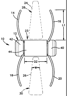
[0071] As shown in FIG. 1, the device 10, referred to herein as a spinous
spacer, may
include a body portion 12, a first set of retainers 14 and 16, and a second
set of retainers 18
and 20. The body portion 12 may have a sleeve 44, a first end portion 40 and a
second end
-13-
CA 02617545 2008-01-31
WO 2007/019391 PCT/US2006/030614
portion 42. The first and second end portion 40, 42 may be moveable relative
to the sleeve
44. It should, however, be understood that those of ordinary skill in the art
will recognize
many modifications and substitutions which may be made to various elements of
the present
invention, and that the embodiments illustrated and described are merely
exemplary.
[0072] The device 10 may be positioned in between spinous processes of
adjacent
vertebrae 28,30 for treating, for example, spinal stenosis. The spinous spacer
10 may be one
member of a set/kit of implants 10 which have different dimensions which takes
into account
the differing anatomy of patients. Although the device 10 is described herein
as being used in
connection with treating spinal stenosis, one of ordinary skill in the art
will readily appreciate
that the device may be used in any other part of the body, including
specifically the spine
where occupying space between portions of the spine and vertebrae may be
desirable. Thus,
the location and/or surgical procedure is not intended to be limiting in any
way.
[0073] The first end portion 40, second end portion 42 and sleeve 44 may be
any
shape, for example, round, oval or polygonal. Moreover, the retainers 14, 16,
18 and 20 may
be straight, concave, convex or any other shape so long as a vertebral body
(e.g. spinous
process) may be positioned between or held by pairs of retainers 14, 16 and
18, 20. The body
portion 12, including the first and second end portions 40, 42 and sleeve 44,
as well as the
retainers 14, 16, 18 and/or 20 may be made of any suitable material,
preferably biocompatible
material, such as metal (e.g., stainless steel, titanium, aluminum, an alloy
of two or more
metals), plastic, polymer, rubber, ceramic, natural body tissue (e.g., bone)
or a composite
material (i.e., made up of two or more materials). Various factors may be
considered when
determining the material used to make the elements of the device 10, including
but not
limited to, for example, ability to withstand sterilization, ability to
withstand forces exerted
thereon, weight, durability, and the ability to grip the device 10,
particularly with latex
gloves. With regard to the retainers 14, 16, 18 and 20, factors may also
include the ability to
-14-
CA 02617545 2008-01-31
WO 2007/019391 PCT/US2006/030614
elastically and plastically bend, and/or deform the retainers 14, 16, 18 and
20 as well as the
ability to retain shape after deformation. The body portion 12 and/or any
other component of
the device 10 may be radiolucent or radioopaque. In embodiments where the body
portion 12
or other components may be radiolucent, radio-opaque marlcers (not shown) may
be
incorporated into or attached to the body portion 12 or other components. The
radio-opaque
marlcers may assist a surgeon in properly aligning the body portion 12 or
other components
relative to a patient's anatomy.
[0074] The retainers 14, 16, 18 and 20 may be sized and configured similar to
each
other and may pass through or under the sleeve 44, first portion 40 and second
portion 42. As
shown in FIGS. 4-6, each retainer 14, 16, 18 and 20 may be an elongated
structure such as,
for examples, a wire 50. The wire 50 may have a gauge of between about 0.01
inches and
about 0.1 inches. Moreover, the wire 50 may have a length of between about 1.0
inch and
about 10 inches before being formed into retainer 14, 16, 18 and 20. The wire
50 may be
generally U-shaped witli a curved portion 56 and arms 52, 54, which may extend
from the
curved portion 56. The curved portion 56 may be curved or bent in more than
one plane as
illustrated in FIGS. 4, 5 and 6. As shown in FIG. 4, the curved portion 56 may
have a radius
of curvature Rl of, for example, between about 0.1 inches and about 1.0 inch,
more
preferably, between about 0.1 inches and about 0.5 inches and, most
preferably, between
about 0.15 inches and about 0.2 inches. As shown in FIG. 5, the curved portion
56 may have
a radius of curvature R2 of, for example, between about 0.01 inches and about
1.0 inch, more
preferably, between about 0.05 inches and about 0.5 inches and, most
preferably, between
about 0.05 inches and about 0.1 inches.
[0075] Furthermore, as illustrated in FIGS. 4 and 6, an end 60 of the arm 52
may be
bent in a first direction at an angle 0 (e.g., about 90 degrees) relative to
the arm 52. The end
62 of the arm 54 may be bent in a second direction, which may be the same or
different
-15-
CA 02617545 2008-01-31
WO 2007/019391 PCT/US2006/030614
direction as the first direction and which may be at an angle a (e.g., about
90 degrees) relative
to the arm 54. In one embodiment, the end 62 may also be bent at an angle
O(e.g., about 15
degrees) (FIG. 6) towards the arm 52. The ends 60 and 62 may be bent at angles
other than
about 90 degrees relative to arms 50, 52, respectively, or may have no bend at
all. End
portions 60 and 62 of each retainer 14, 16, 18 and 20 may be operably
connected to an end
portion 40, 42. Moreover, the curved portions 56 of each retainer 14, 16, 18
and 20 may be
slidably associated with, retained by, guided by or connected to the other end
portion 40, 42.
[0076] As shown in FIGS. 7 and 8, the first end portion 40 may comprise an end
cap
64 and an inner portion 66, each of which may have a generally cylindrical
configuration and
which may be centered on the axis 43. An end 68 of the inner portion 66 may be
received in
a groove 69 within the end cap 64 so that the inner portion 66 and the end cap
64 may be
connected together. The end 68 may have a conical configuration; however,
those skilled in
the art will appreciate that other shapes may be used so long as the end 68
may be held in the
end cap 64.
[0077] As shown in FIGS. 10 and 11, the end cap 64 may have first and second
cam
surfaces 70, and first and second teeth 72 proximate the cam surfaces 70. The
cam surfaces
70 may have an angle (3 of, for example, between about 90 degrees and about
160 degrees,
more preferably, between about 100 degrees and about 135 degrees and, most
preferably,
between about 105 degrees and about 115 degrees. The teeth 72 and cam surfaces
70 may be
located within diainetrically opposed openings 73 in the end cap 64.
[0078] Moreover, as shown in FIGS. 12, 13 and 14, the inner portion 66 may
have a
first and second upper slot 76, 78, respectively. A notch 80 at the end of the
first upper slot
76 may extend at an angle 2, (e.g., about 90 degrees) relative to the slot 76
(e.g., a downward
angle) and a notch 82 at the end of the second upper slot 78 may extends at an
angle (e.g.,
about 15 degrees) relative to the slot 78 (e.g., upward and toward the first
upper slot 76). The
-16-
CA 02617545 2008-01-31
WO 2007/019391 PCT/US2006/030614
angle of the notch 80 relative to the slots 76 may correspond to the angle 0
of end 60 of the
retainers 14, 16, 18 and 20. The angle of the notch 82 relative to the slots
78 may correspond
to the angle O of the end 62 of the retainers 14, 16, 18 and 20. The inner
portion 66 may also
have first and second lower slots 84 and 86, which may have notches 88 and 90,
respectively.
The notch 88 at the end of the first lower slot 84 may extend at an angle
6(e.g., about 15
degrees) relative to the slot 84 (e.g., notch 88 may be angled downward and
away from the
second lower slot 86) and the notch 90 at the end of the lower slot 86 may
extends at an angle
p (e.g., about 90 degrees) relative to the slot 86 (e.g., an upward angle).
The angle of the
notch 88 relative to the slots 84 may correspond to the angle O of the end 62
of the retainers
14, 16, 18 and 20. The angle of the notch 90 relative to the slots 86 may
correspond to the
angle 0 of end 60 of the retainers 14, 16, 18 and 20.
[0079] As illustrated in FIGS. 15 and 16, at least a portion of the retainers
14 and 16
may be positioned beside each other and generally inside the body portion 12
when in the
deployed or undeployed position. As shown in FIG. 16, the arms 52 and 54 of
the retainers
14 and 16 may be received in the first and second upper slots 76 and 78 in the
inner portion
66 of the first end portion 40. The ends 60 and 62 (FIG. 17) of the retainer
14 may be
received in the notches 80 and 82, respectively, at the ends of the first and
second upper slots
76 and 78, respectively, of the first end portion 40 such that the retainer 14
may be fixed with
respect to the first end portion 40. The curved portion 56 of the retainer 16
may be
positioned adjacent the cam surface 70 (FIG. 7) on the end cap 64 of the first
end portion 40,
and may be positioned around the tooth 72 such that the retainer 16 may slide
with respect to
the end cap 64 of the first end portion 40. The arms 52 and 54 of the
retainers 14 and 16 may
also be received in the first and second upper slots 76 and 78 in an inner
portion 66 of the
second end portion 42. The ends 60 and 62 of the retainer 16 may be received
in the notches
80 and 82, respectively, at the ends of the first and second upper slots 76
and 78, respectively,
-17-
CA 02617545 2008-01-31
WO 2007/019391 PCT/US2006/030614
of the second end portion 42 such that the retainer 16 may be fixed with
respect to the second
end portion 42. The curved portion 56 of the retainer 14 may be positioned
adjacent the cam
surface 70 on the end cap 64 of the second end portion 42, and may be
positioned around the
tooth 72 such that the retainer 14 may slide with respect to the end cap 64 of
the second end
portion 42.
[0080] Similarly, at least a portion of the retainers 18 and 20 may be
positioned
beside each other and generally inside the body portion 12 when in the
deployed or
undeployed position. As shown in FIG. 16, the arms 52 and 54 of the retainers
18 and 20
may be received in the first and second lower slots 84 and 86 in the inner
portion 66 of the
first end portion 40. The ends 60 and 62 (FIG. 17) of the retainer 18 may be
received in the
notches 90 and 88, respectively, at the ends of the first and second lower
slots 86 and 84,
respectively, of the first end portion 40 such that the retainer 18 may be
fixed with respect to
the first end portion 40. The curved portion 56 of the retainer 20 may be
positioned adjacent
the cam surface 70 (FIG. 7) on the end cap 64 of the first end portion 40, and
may be
positioned around the tooth 72 such that the retainer 20 may slide with
respect to the end cap
64 of the first end portion 40. The arms 52 and 54 of the retainers 18 and 20
may also be
received in the first and second lower slots 84 and 86 in an inner portion 66
of the second end
portion 42. The ends 60 and 62 of the retainer 16 may be received in the
notches 90 and 88,
respectively, at the ends of the first and second lower slots 86 and 84,
respectively, of the
second end portion 42 such that the retainer 20 may be fixed with respect to
the second end
portion 42. The curved portion 56 of the retainer 18 may be positioned
adjacent the cam
surface 70 on the end cap 64 of the second end portion 42, and may be
positioned around the
tooth 72 such that the retainer 18 may slide with respect to the end cap 64 of
the second end
portion 42.
-iR-
CA 02617545 2008-01-31
WO 2007/019391 PCT/US2006/030614
[0081] As shown in FIGS. 7-9, the end cap 64 and inner portion 66 of the
second end
portion 42 may be identical to the end cap 64 and inner portion 66 of the
first end portion 40.
Within the body portion 12, the retainers 14 and 16 generally may be
positioned beside each
other. The arms 52 and 54 of the retainers 14 and 16 may be received in the
first and second
upper slots 76 and 78 in the inner portion 66. The ends 60 and 62 (FIG. 17) of
the retainer 16
may be received in the notches 80 and 82, respectively, at the ends of the
first and second
upper slots 76 and 78, respectively. The curved portion 56 of the retainer 14
may be
positioned adjacent the cam surface 70 (FIG. 8) on the end cap 64, and may be
positioned
around the tooth 72. Similarly, the retainers 18 and 20 generally may be
positioned beside
each other in the body portion 12. The arms 52 and 54 of the retainers 18 and
20 may be
received in the first and second lower slots 84 and 86 in the inner portion
66. The ends 60
and 62 of the retainer 20 may be received in the notches 90 and 88,
respectively, at the ends
of the first and second lower slots 86 and 84, respectively. The curved
portion 56 of the
retainer 18 may be positioned adjacent the cam surface 70 on the end cap 64,
and may be
positioned around the tooth 72.
[0082] A connector 100 may extend along the axis 43 between the end portions
40
and 42 of the body portion 12. As shown in FIG. 18, the connector 100 may have
external
screw-threads and may have sections 102, 104. Each section 102 and 104 may
have a recess
105 for receiving an actuation tool (e.g., actuation tool 184 of FIG. 36). The
recess 105 may
have gripping surfaces for engaging corresponding gripping surfaces on an
actuation tool
(e.g., the recess 105 may be polygonal in shape). The sections 102 and 104
also have
respective screw threads 106 and 108 which may extend around the connector 100
in
opposite directions relative to each other (e.g., section 102 may have riglit
handed threads
106; section 104 may have left handed threads 108). As shown in FIGS. 7 and 9,
the screw
threads 106 and 108 on the connector 100 may engage corresponding internal
screw threads
-19-
CA 02617545 2008-01-31
WO 2007/019391 PCT/US2006/030614
114 on the inner portions 66 of end portions 40 and 42 of the body portion 12.
Such a
configuration may enable the end portions 40 and 42 to move along the
connector 100 axially
toward or away from each other upon rotation of the connector 100 relative to
the inner
portions 66.
[0083] When the two end portions 40 and 42 move axially toward each other, the
retainers 14, 16, 18 and 20 may move with respect to the end portions 40, 42.
The retainers
14, 16, 18 and 20 may move with the end caps 64 and inner portions 66 to which
the ends 60,
62 of the retainers 14, 16, 18 and 20 may be attached. As the end portion 40
moves, the
retainers 14 and 18 which may be fixed in the end cap 64 of the first end
portion 40 may also
move so that the curved portions 56 of the retainers 14 and 18 may be pushed
forcefully
against the cam surfaces 70 on the end cap 64 of the second end portion 42.
Similarly, as the
end portion 42 moves, the retainers 16 and 20 which may be fixed in the end
cap 64 of the
second end portion 42 may also move so that the curved portions 56 of the
retainers 16 and
20 may be pushed forcefully against the canl surfaces 70 on the end cap 64 of
the first end
portion 42. The cam surfaces 70 may guide the curved surfaces 56 so that the
retainers 16
and 20 may move outward through the openings 73 in the end cap 64 of the first
end portion
40 and the retainers 14 and 18 may move outward through the openings 73 in the
end cap 64
of the second end portion 42. More specifically, the arms 52 and 54 of the
retainer wires 50
may also move outward through the openings 73 as the end portions 40 and 42 of
the body
structure 12 continue to move axially toward each other. The arms 52 and 54
may be
deflected (e.g., along an arcuate or straight path) as the arms 52 and 54
slide outward against
the cam surfaces 70. The retainers 14, 16, 18 and 20 may be pre-bent so that
they resume the
bent configuration once extended from the ends 40, 42 (e.g., the retainers 14,
16, 18 and 20
may have a shape memory). Alternatively, the retainers 14, 16, 18 and 20 may
be deformed
(elastically or plastically) as the retainers 14, 16, 18 and 20 move out of
the body portion 12.
-20-
CA 02617545 2008-01-31
WO 2007/019391 PCT/US2006/030614
When the retainers 14, 16, 18 and 20 extend out of the end portions 40, 42,
the retainers 14,
16, 18 and 20 may be positioned around adjacent spinous processes in the
deployed position,
and the retainers 14, 16, 18 and 20 may help to hold the device in position or
retain the device
between adjacent spinous processes as shown in FIG. 1. In a deployed position,
the retainers
14, 16, 18 and 20 may extend away from the body a length L1 (FIG. 1) which may
be, for
example, between about 0.2 inches and 2.0 inches, more preferably, between
about 0.3 inches
and 1.0 inch and, most preferably, between about 0.4 inches and about 0.6.
inches.
Moreover, in a deployed position, the retainers 14 and 16, 18 and 20 may have
a dimension
D2 (FIG. 1) between adjacent retainers 14 and 16, 18 and 20 which may be
substantially the
same as the length L2 of the sleeve 44 (FIG. 19). The dimension D2 may be at
least, for
example, between about 0.1 inch and 2.0 inches, more preferably, between about
0.2 inches
and 1.0 inches and, most preferably, between about 0.4 inches and about 0.5
inches.
Moreover, In addition, retainers 14, 16, 18 and 20 may be retracted into the
body portion 12.
[0084] The sleeve 44 may also help to hold the body portion 12 in position
between
adjacent spinous processes as shown in FIG. 1. In the expanded configuration
of FIG. 2, the
sleeve 44 may be freely movable axially and rotationally relative to the other
parts of the
implant 10 (e.g., the end portions 40, 42 and retainers 14, 16, 18 and 20). In
the contracted
configuration of FIG. 3, the sleeve 44 may be captured between the end
portions 40 and 42
and may be prevented from moving axially about axis 43. In one embodiment, the
sleeve 44
may be fixed with respect to the connector 100 such that the sleeve 44 may not
move axially
relative to the connector 100. The sleeve 44 may, however, be free to rotate
relative to the
end portions 40 and 42 as well as the retainers 14, 16, 18 and 20. If bending
or other
movement of the spine causes the spinous processes 24 and 26 to impart
rotational forces to
the sleeve 44, those forces may be dissipated by rotation of the sleeve 44
relative to the other
parts of the implant 10. Such a construction may prevent the transmission of
rotational forces
-21-
CA 02617545 2008-01-31
WO 2007/019391 PCT/US2006/030614
from the sleeve 44 to the retainers 14, 16, 18 and 20 and, thereby, may help
prevent unwanted
rotation and/or displacement of the retainers 14, 16, 18 and 20.
[0085] As shown in FIG. 19, the sleeve 44 may have an outer surface 120 with a
diameter D, which may be uniform along the length of the sleeve 44 (e.g., the
sleeve may
have a cylindrical contour). For example, the diameter may be between about
0.1 inches and
about 1.0 inches, more preferably, between about 0.15 inches and about 0.8
inches and, most
preferably, between about 0.235 inches and about 0.63 inches. The sleeve may
have a
thickness T, for example, between about 0.01 inches and about 0.15 inches,
more preferably,
between about 0.02 inches and about 0.07 inches and, most preferably, between
about 0.035
inches and about 0.05 inches. As shown in FIG. 8, the end caps 64 of the end
portions 40, 42
may have diameters which may be substantially similar to the diameter D. An
inner surface
122 of the sleeve 44 may have a contour (e.g., convex contour) which may be
curved radially
outward. The inner surface 122 may define a tapered central section 124 of the
sleeve 44
wlzich may be thinner than the sections 126 at opposite ends of the sleeve 44.
Such a
construction may provide greater flexibility to the sleeve 44 at the central
section 126 so that
the sleeve 44 may be deflected radially inward under forces applied from the
spinous
processes 24 and 26.
[00861 It should be noted that in some embodiments, a sleeve 44 may be
unnecessary.
For example, as shown in FIGS. 7A and 7B, the first end portion 40 may have an
extended
wall portion 40a. When the implant is in the contracted configuration, the
extended wall 40a
may be positioned between adjacent spinous processes. In an alternative
embodiment, as
shown in FIGS. 7C and 7D, the first end portion 40 and second end portion 42
may have
extended wall portions 40a and 42a, respectively. When the implant is in the
contracted
configuration, the extended walls portions 40a, 42a may be positioned between
the adjacent
spinous processes.
-22-
CA 02617545 2008-01-31
WO 2007/019391 PCT/US2006/030614
[0087] In use, the body portion 12 may be inserted in the space 23 between the
spinous processes 24 and 26 of adjacent vertebrae 28 and 30 (shown
schematically). The
body portion 12 may have a first, expanded configuration such as shown in FIG.
2. In such a
configuration, the body may have a length L (FIG. 7) of, for example, between
about 0.15
inches and about 5.0 inches, more preferably, between about 0.5 inches and
about 2.0 inches
and, most preferably, between about 1.2 inches and about 1.4 inches. In the
first
configuration, end portions 40 and 42 of the body structure 12 may be spaced
apart from each
other along a longitudinal central axis 43. The sleeve 44 may be positioned
between the end
portions 40 and 42. In the expanded configuration, the retainers 14, 16 and
18, 20 may be
located in a retracted or undeployed position such that the retainers 14, 16
and 18, 20
generally may be positioned within the body portion 12. Such a construction
may enable the
body portion to be inserted in between the spinous processes 24 and 26 from
the side of the
spine, (e.g., lateral insertion). Once the spinous spacer 10 is positioned
between the spinous
processes 24, 26, the body portion 12 may be moved to a second, contracted
configuration
such as shown in FIG. 3. To accomplish this, the end portions 40 and 42 may be
moved
axially toward each other. In the contracted configuration, the body 12 may
have a length L
(FIG. 7) of, for example, between about 0.05 inches and about 2.0 inches, more
preferably,
between about 0.5 inches and about 1.5 inches and, most preferably, between
about 0.7
inches and about 0.9 inches. As the end portions 40 and 42 move towards each
other, the
retainers 14, 16, 18 and 20 may be moved out of the body 12 from the retracted
position to
the deployed position of FIG. 3. In the deployed position, the retainers 14
and 16 may extend
away from the body portion 12 and may be positioned on opposite sides of the
spinous
process 24 on the vertebrae 28. The retainers 18 and 20 may extend away from
the body
portion 12 and may be positioned on opposite sides of the spinous process 26
on the vertebrae
30. In this arrangement, the body portion 12 may help maintain a desired
spacing between
- 23 -
CA 02617545 2008-01-31
WO 2007/019391 PCT/US2006/030614
the adjacent spinous processes 24 and 26. Furthermore, the retainers 14, 16,
18 and 20 may
help to hold the body portion 12 in place with respect to the spine and/or
surrounding soft
tissue.
[0088] Various instruments may be used for insertion and/or removal of the
implants
such as, for example, an implant holder 140, guide wire 170, dilator 176,
insertion tubes
180, 182, actuation tool 184 and removal tool 290. While the instruments
described below
may be used with the implant 10, one of ordinary skill in the art will readily
appreciate that
aiiy number of instruments may be used in place of those described herein.
[0089] The implant holder 140 of FIGS. 22-24 may include an elongated stein
142
and a handle 144. The elongated stem 142 may be hollow (e.g., tubular) and may
extend
from the handle 144 and has a distal end 143. A wheel 148 may be positioned on
the handle
144. A shaft 146, which may also be hollow, may extend through the stem 142,
and may be
operably connected to the wheel 148 so that rotation of the wheel 148 may
result in rotation
of the shaft 146 relative to the stem 142. As shown in FIG. 24, the distal end
143 of the shaft
146 may protrude from an open end 150 of the stem 142 and may have a screw-
thread 152.
A pair of protrusions 154, which may be diametrically opposed to each other
(one of which is
shown in FIG. 24), may project axially outward from the open end 150 of the
stem 142
proximate the shaft 146. It should be noted that in some embodiments, one or
more
protrusions 154 may be used.
[0090] The implant inserter 140 may engage the first or second end portions
40, 42
and may be used as an insertion tool for moving the implant 10 into its
installed position from
the side of the spine. As shown in FIGS. 20 and 21, the end caps 64 of the
first and/or second
end portions 40, 42 may have a pair of slots 130 at an outer end 132. It
should be noted,
however, that the end portions 40, 42 may have one or more slots 130, which
may be engaged
by one or more protrusions 154 of the stem 142. Moreover, the first and/or
second end
-24-
CA 02617545 2008-01-31
WO 2007/019391 PCT/US2006/030614
portions 40, 42 may have an internal screw thread 134 which may extends
axially inward
from the outer end 132. The screw-thread 152 of the shaft 146 may engage the
screw thread
134 of the first or second end portions 40, 42. Thereafter, the wheel 148 may
be rotated to
draw the holder 140 and, consequently, the protrusion(s) 154 of the holder 140
towards the
first or second end portions 40, 42 so that the protrusion(s) 154 may be
inserted into the
slot(s) 130 of the first or second end portions 40, 42. The construction of
the end portions 40,
42 and the holder 140 may prevent the end portions 40, 42 and retainers 14, 16
18 and 20
from rotating relative to the holder 140 about the axis 43.
[0091] The spinous spacer 10 may be inserted into the body using, for example,
a
lateral approach to the spine. An incision may be made in a patient's side. A
guide wire 170,
such as shown in FIG. 25, may be inserted through the incision. A distal end
194 of the guide
wire 170 may be sharpened to assist the guide wire 170 in penetrating soft
tissue. A proximal
end 190 of the guide wire 170 may have an engagement portion such as, for
example, an
inner screw-threaded counterbore 192. A surgeon may grasp the guide wire 170
directly or
may use a holder 172 to hold the guide wire 170. The holder 172 may have a
handle 172, a
passage 195, and a tightening member, such as a screw 196, intersecting the
passage 195.
The guide wire 170 may be clamped in place in the passage 195 by tightening
the screw 196.
The guide wire 170 may be attached to the holder 172 before or after the guide
wire 170 is
inserted into the body. In many cases, the guide wire 170 may be long enough
for a surgeon
to extend the distal end 194 of the guide wire 170 into the space 23 between
the adjacent
spinous processes 24 and 26. However, in some cases a surgeon may have to
extend the
length of the guide wire 170 using an extension 174.
[0092] The extension 174 may be an elongated member (e.g., rod or bar) having
a
distal end 200 and a proximal end 202. The distal end 204 may have a
engagement portion
204, which may be in the form of screw threads. The distal end 204 may have a
reduced
-25-
CA 02617545 2008-01-31
WO 2007/019391 PCT/US2006/030614
diameter as compared to the rest of the extension 174. The engagement portion
204 of the
extension 174 may be screwed into the counterbore 192 in the proximal portion
190 of the
guide wire 170.
[0093] After the guide wire 170 is in place in the body, a dilator 176 may be
positioned over the guide wire 170 and/or extension 174 (if used), and may be
moved toward
the spine by sliding the dilator 176 along the guide wire 170 and/or extension
174. As shown
in FIG. 28, the dilator 176 may be a hollow tubular structure with a passage
205
therethrough. The distal end 208 of the dilator 176 may have a tapered surface
206. As the
tapered surface 206 of the dilator 176 moves toward aiid into the space 23
between the
spinous processes 22 and 24, the tapered end 206 may dilate the soft tissue. A
pin 210 may
extend into the passage 205 near the proximal end 212. As shown in FIG. 29,
the dilator 176
may be positioned and moved over the guide wire 170 and/or extension 174 until
the pin 210
engages the proximal end 190 of the guide wire 170 and/or proximal end 202 of
the extension
174. The length of the dilator 176 may be correlated to the length of the
guide wire 170 such
that the pin 210 on the dilator 176 may abutinent the proximal end 19.0 of the
guide wire 170
to prevent movement of the dilator 176 once the tapered surface 206 reaches
the space 23
between the spinous processes 24 and 26. It should be noted that one or more
sequential
dilators may be placed over the dilator 176 and may be used to dilate the
opening through
tissue from the skin to the vertebrae.
[0094] After the dilator 176 is positioned in the body, tubes 180 and 182 may
be
positioned over the dilator 176. The tubes 180, 182 may be part of a set of
tubes which differ
in size (e.g., diameter/dimension) to accommodate different patient anatomies.
For example,
the diameter/dimension of the tubes may be between about 0.1 inches and about
1.0 inches,
more preferably, between about 0.15 inches and about 0.8 inches and, most
preferably,
between about 0.25 inches and about 0.65 inches. The tube may be used to
distract tissue as
-26-
CA 02617545 2008-01-31
WO 2007/019391 PCT/US2006/030614
well as the space in between the spinous processes of adjacent vertebrae. The
tube 180 of
FIGS. 30-32 may have a configuration similar to the tube 182 of FIGS. 33-35.
Tube 180 may
have a smaller diameter and may be shorter than tube 182. All tubes in the set
of tubes,
including tubes 180, 182 may be cylindrical and each tube with a larger
diameter may be
sized to fit closely over the tube with the next smallest diameter. In this
way, all of the tubes
in the set may be nested concentrically together. In addition, certain tubes
may correspond to
the different sized devices 10. These tubes may be configured such that the
tube has an inner
diameter closely matching the outer diameter D of the spinous spacer 10. Such
a construction
may enable a device 10 to slide closely and smoothly through its corresponding
tube when
the spinous spacer 10 is in the extended configuration of FIG. 2. The tubes
may also have
two slots 260 which may enable retainers 14, 16, 18 and 20 to be deployed
through the tube
as described below. In otller embodiment the tubes may have one slot 260.
[0095] In use, the surgeon may first select a tube having a first dimension
D1, such
as, for example, the tube 180 shown in FIG. 30. Similar to other tubes, tube
180 may have a
tapered distal end 220. The surgeon may move the tube 180 over the guide wire
170 and/or
dilator 176 (i.e., the assembly of FIG. 29) so that the tube 180 may move
along the dilator
176 toward the distal end 208 of the dilator 176. As the tapered distal
portion 220 of the tube
180 is moved into the space 23 between the spinous processes 24 and 26, it may
dilate the
soft tissue as well as distract the spinous processes 24 and 26. Further
dilation and distraction
may be accomplished by moving successively larger dimensioned tubes over
smaller tubes.
This process may be repeated until dilation and distraction is completed by a
final outennost
tube such as, for exainple, tube 182 of FIG. 33 (i.e., dilation/distraction
continues until
adjacent spinous processes are separated by a desired distance). In order to
help properly
position the tubes in between adjacent vertebrae, the tubes may have at least
one pair of
indication slots 266. The indication slots 266 may be spaced axially from the
distal end 262
-27-
CA 02617545 2008-01-31
WO 2007/019391 PCT/US2006/030614
of the tubes and may be diametrically opposed to each other. When looking at
the tubes 180,
182 from the view shown in FIG. 30 and 33, the indication slots 266 may
overlap each other
and may be oriented at an angle with respect to each other. For example, the
indication slots
266 may be at a 90 degree angle to each other so that their overlapping x-ray
image may form
an "X" when the tube is viewed in the orientation shown in FIGS. 30 or 33.
Such a
configuration may be used to produce shapes when viewing an x-rays. As shown
in the
embodiment of FIGS. 30 and 33, another pair of indication slots 268 may be
provided on tube
180, 182 more proximal than slots 266. The pairs of indication slots 266 and
268 may
enable a surgeon to rotate the tube until the "X" images are formed in an x-
ray view from the
rear of the spine. Once the "X" image is visible, this may indicate that the
tube and, in
particular, the slots 266 are correctly oriented for deployment of the
retainers 14, 16, 18 and
20 therethrough.
[0096] As seen in FIG. 33, each tube may have a knob 222 at its proximal end
224
which may project inwardly in the passage through the tube. When a larger tube
is placed
over a smaller tube, the knob 222 on the larger tube may move into abutinent
with the distal
most end 224 of the smaller tube. Such a construction may limit movement of
larger tubes
over small tubes so that the tapered distal end 220 of the concentric tubes
overlap at the same
location between the spinous processes 24 and 26.
[0097] Each tube may also have a pair of slots 230 at its proximal end 224.
The slots
230 may delineate an opposed pair of sections 232, which may be deflectable.
The section
232 may be axially aligned with the knob 222 but may be spaced a short
distance axially
from the knob 222. In order to remove smaller tubes (e.g., tube 180) from the
outermost tube
182, a surgeon may push the proximal end 224 at a location 224a opposite the
knob 222 (e.g.,
at a location approximately 180 degrees from the knob) in a direction towards
the knob 222
(e.g., in a direction perpendicular to the longitudinal axis of the outermost
tube 182). The
-28-
CA 02617545 2008-01-31
WO 2007/019391 PCT/US2006/030614
slots 230 may enable the proximal end 224 of the tube 182, including the lcnob
222 and
sections 232, to be deflected upward as shown in FIG. 30 so that the
concentric inner tubes
can be removed together from the outermost tube 182. The guide wire 174 and
the dilator
176 may also be removed from the outermost tube 182. With the tube 182
positioned in
between the spinous processes 24 and 26, the surgeon may select a device 10 of
a size
corresponding to the inner dimension of the outermost tube 182. A surgeon may
then attach
the selected device 10 to the implant holder 140, and may move the device 10
through the
tube 182 towards and in between the spinous processes 24 and 26. The implant
10 is
connected to the iinplant holder preferably so that the longitudinal axis of
the implant 10 is
aligned and coincident with the longitudinal axis of the implant holder 140.
[0098] The implant holder 140 may be inserted into the tube 182 until the
proximal
most portion 224 of the outermost tube engages a stepped portion 250 (FIGS. 22
and 23) of
the holder 140. The stepped portion 250 may have dimensions so that each step
matches the
inner diameters of a tube in the set of tubes (e.g., tubes 180, 182). Each
step 250 may also
have a notch 252 to receive the knob 222 on the corresponding tube. Such a
construction
may assist in positioning the implant in the proper location between adjacent
spinous
processes 24, 26 (i.e., the stepped portion 250 may act as a stop, which may
prevent the
device 10 from being inserted too far through the tube) as well as aligning
the retainers 14,
16, 18 and 20 with the slots 260 (i.e., positioning the knob 222 in the notch
252 may prevent
rotational misalignment).
[0099] During insertion of dilator, dilation tubes and/or insertion tubes
substantial
resistance caused by soft tissues, scar tissues or ligaments may be
encountered. At times,
even the use of a hammer may be necessary to allow controlled insertion of
these
instruments. Resistance to insertion of instruments may make it more difficult
to insert
instruments in the body if the outer diameters of these instruments are too
small to provide
-29-
CA 02617545 2008-01-31
WO 2007/019391 PCT/US2006/030614
appropriate grip for the surgeon's hands. As shown in FIG. 35A, a handle 600
may be used
to provide an enhanced gripping surface to insert, for example, dilator 176
and tubes 180 and
182. Additionally, the handle may provide a surface for hammering the
instruments into the
body without causing damage to the instruments. The handle 600 or its portions
may be
made of, for example, polymer, metal or ceramic.
[00100] The handle 600 may be configured so that the handle 600 may be adapted
to
instruments having different dimensions. For example, the handle 600 may be
designed to
engage instruments which have a dimension or diameter of between about 8 mm
and about
18 min. The handle 600 may have an ergonomically shaped body 601 and an
engagement
mechanism to grip the different dimensioned instruinents. The engagement
mechanism may
be similar to parallel forceps. As illustrated in FIGS. 35B and 35C, the
engagement
mechanism may have a plurality of prongs 602 which may engage on the outer
surface of an
instruinent (e.g. tube 180, 182) to grip the instrument. At least one prong
602 may have one
or more ridges 604 for engaging an instrument. In an embodiment where the
handle 600 is
used with the tube 180, 182, the ridges 604 may engage one or more slots 270
of the tube
180, 182. Rotational movement about the axis of the tube 180, 182 and linear
movement
perpendicular to the axis of tube 180, 182 (i.e., away from the axis of the
tube) may be
prevented by the engagement of the ridges 604 with the slots 270.
[00101] The prongs 602 may be moved relative to each other (e.g., towards
and/or
away from each other) by movement of a knob 610. The knob 610 may have a cap
620 and a
locking mechanism 630, which may be threaded. The cap 620 may be designed so
that a
surgeon may impact the cap 620 with a hammer. For instance, the cap 620 may be
made of a
material which may reduce peak loads at the impact of hammering (e.g.,
polymer, metal,
ceramic). Movement of the cap 620 along the axis A of the handle 600 may move
the prongs
602 relative to each other. As the cap 620 is pushed forward towards distal
end 603, the
-30-
CA 02617545 2008-01-31
WO 2007/019391 PCT/US2006/030614
prongs 602 may open, thereby allowing an instrument to be inserted into the
body 601. The
prongs 602 may be spring loaded so that the prongs 602 may close when the cap
620 is
released, thereby engaging the instruinent (e.g., tube 180, 182). In order to
prevent the
prongs 602 from inadvertently opening and/or separating from the instrusnent,
the locking
mechanism 630 may be rotated until the locking mechanism 630 engages the body
601 of the
handle 600. It will be appreciated that other means of moving and loclcing the
prongs 602 are
envisioned. Moreover, while the handle 600 is described in the context of use
with spinal
instruments, those skilled in the art will appreciate that the handle 600 may
sized and
configured to engage other instruments for performing procedures anywhere else
in or on the
body.
[00102] Once the device 10 and holder 140 are in place (i.e., at the distal
end 220 of
the tube 182), the actuation tool 184 shown in FIG. 36 (e.g., screwdriver) may
be inserted
through the hollow shaft 146 on the holder 140. Alternatively, the holder 140,
actuation tool
184 and device 10 may be attached together before placement in the body and
inserted into
the body as a single unit. The tool 184 may be inserted through the holder 140
until an
engagement portion 254 of the tool 184 is received in the recess 105 of the
connector 100.
The tool 184 may then be rotated while the holder 140 is held in position. The
tool 184 may
cause the connector 100 to rotate and the holder 140 may prevent rotational
movement of the
end portions 40, 42. In this way, the end portions 40, 42 may move axially
along the axis 43
towards each other. As the end portions 40, 42 move towards each other, the
retainers 14, 16,
18 and 20 may be deployed from the body portion 12 and may be positioned
around adjacent
spinous processes 24, 26. It should be noted that the end portions 40, 42 may
move towards
each other until the retainers 14, 16, 18 and 20 tightly grip or firmly engage
the spinous
processes, thereby holding the device 10 in place. The distance between the
end portions 40,
42 when the retainers 14, 16, 18 and 20 are in the fully deployed position may
depend on the
-31-
CA 02617545 2008-01-31
WO 2007/019391 PCT/US2006/030614
length Ll of the retainers 14, 16, 18 and 20 when at least a portion of the
retainers 14, 16, 18
and 20 engage the spinous processes. The length L1 of the retainers 14, 16, 18
and 20, in
turn, may depend on the width W (FIG. 1) of the spinous processes.
[00103] The retainers 14, 16, 18 and 20 may be deployed from the body portion
12
outwardly through the slots 260 of the tubes. The slots 260 may extend axially
from the
distal most end 262 of each tube towards the proximal end 224. The slots 260
may be
diametrically opposed to each other and may be configured so that the tube 182
may be
moved over the device 10 (e.g., slide on and off the device 10) after the
retainers 14, 16, 18
and 20 have been deployed around the spinous processes. A pair of slots 270
near the
proximal end 224 of the tubes may serve as viewing windows, which may enable
an operator
to align the slots 260 (and thereby the retainers 14, 16, 18 and 20) in the
cranio-caudal
direction.
[00104] With the retainers 14, 16, 18 and 20 deployed and the device 10 in
position,
the tool 184 may be withdrawn from the holder. The holder 140 may be detached
from the
device 10 by rotating the wheel 148. Thereafter, the holder 140 may be
withdrawn from the
tube 182. The tube 182 may then be removed from the patient, leaving the
device 10 in
between the adjacent spinous processes 24, 26.
[00105] As shown in FIG. 37, a removal too1290 may be used to retract
retainers 14,
16, 18 and 20 into the body portion 12 and remove the device 10 from the body.
The
removal tool 280 may be a elongated member (e.g., rod) having a proximal end
292 and two
distinct engagement portions 294 and 296. The proximal portion 292 may be
sized and
configured for engagement with a handle, drill or some other device which may
impart
rotation motion. The first engagement portion 296 may have a screw thread 298
so that the
too1290 may be inserted into the open outer end 132 (FIG. 21) of the end
portion 64. The
-32-
CA 02617545 2008-01-31
WO 2007/019391 PCT/US2006/030614
second engagement portion 294 may be sized and configured (e.g., may have a
polygonal or
hex shape) to engage the recess 105 (FIG. 18) of the connector 100.
[00106] In order to remove the spinous spacer 10 from the spine, a surgeon may
use a
lateral approach to the spine. An incision may be made in the side of a
patient and the tool
290 may be inserted into the body until the second engagement portion 294 of
the tool 290
may be inserted in the recess 105. The tool 290 may be used in place of the
guide wire 170
and/or the extension 174. A dilator 176 may be inserted over the tool 290.
Sequentially
larger tubes 180, 182, etc. may be inserted over dilator 176 and into the
space 23 between the
adjacent spinous processes 24 and 26. When dilation and distraction are
completed by
placement of an outermost tube 182, the smaller tubes and/or dilator 176 may
be removed
from the tube 182.
[00107] The tool 290 and the connector 100 may then be rotated to drive the
end
portions 40 and 42 of the body portion 12 axially away from each other. As the
body portion
12 moves from the contracted configuration of FIG. 3 to the expanded
configuration of FIG.
2, the retainers 14, 16, 18 and 20 may be drawn back into the body portion 12
from the
deployed positions to the retracted positions. As the end portion 42 moves
axially toward the
adjacent end of the connector 100, the screw thread 298 of the first
engagement portion 296
may engage the internal screw thread 114 (FIGS. 7 and 9) of the inner portion
66 of the end
portion 42. Such a configuration may cause the tool 290 to engage the device
10 in a manner
similar to attachment of the implant holder 140. The rod 290 may then be used
to pull the
spinous spacer 10 through the tube 182.
[00108] FIGS. 38-40 illustrate anotlZer embodiment of an implant for treating
spinal
stenosis. The device 300 may be part of set of implants which may have
different sizes to
accommodate different anatomies. The body portions 302 may be configured for
installation
between a pair of adjacent spinal processes 24 and 26 (FIG. 1) by use of the
installation
-33-
CA 02617545 2008-01-31
WO 2007/019391 PCT/US2006/030614
devices described above. The body structure 302 may have first and second end
portions 304
and 306, which may be centered on a longitudinal axis 307. A sleeve 308 may be
freely
movable axially and rotationally between the two end portions 304 and 306 of
the body
portion 302.
[00109] The first end portion 304 may have a base 310, which may be generally
dome-
shaped. A stem 312 may project axially from the base 310. The stem 312 may be
any shape,
for example, cylindrical. A first hinge 320 may operably connect a first
retainer 322 to the
base 310. Alternatively, the first hinge may operably connect the first
retainer 322 to the
stem 312. The hinge 320 may have a pivotal axis 323, wliich may be
perpendicular to the
longitudinal axis 307 of the body portion 302. First hinge 320 may comprise a
pin about
which the first retainer 322 may pivot or rotate. A second retainer 326 may be
operably
connected to the stem 312 by a second hinge 328, which may have a pivotal axis
329 which
may be parallel to the first pivotal axis 323. Second hinge 328 may coinprise
a pin about
which the second retainer 326 may pivot or rotate. A third and fourth retainer
340 and 342
may be operably connected to the base 310 and the stem 312, respectively, by a
third and
fourth hinge 344 and 346, respectively. The hinges 344 and 346 may have axes
347 and 349,
respectively, which may be parallel to each other.
[00110] The device 300 may have an internal coiulector (not shown) which may
be
substantially similar to the connector 100 of the device 10. Accordingly, the
connector of the
implant 300 may have two sections with screw threads in opposite directions
and each section
may engage an end portion 304 and 306. Rotation of the connector about axis
307 may result
in the end portions 304 moving axially toward each other. An opening 350 in
the first end
portion 302 may provide access for an actuation tool (e.g. screwdriver) to
engage the
connector such that the body portion 302 may be moved from the extended
configuration of
FIGS. 38 and 39 to the contracted configuration of FIG. 40.
-34-
CA 02617545 2008-01-31
WO 2007/019391 PCT/US2006/030614
[00111] When the end portions 304 and 306 are moved axially together, the
first
retainer 322 and the third retainer 340 may contact surface 352 of the sleeve
308, and the
sleeve 308 as it moves will push the first and third retainers 322, 240
outwardly away from
axis 307. Moreover, as the second end portion 306 moves inward, the second
retainer 326
and the fourth retainer 342 may move or be pushed against cam surfaces 354,
which may be
positioned within openings 355 of the second end portion 306. In this way, the
retainers 326
and 342 may move outwardly from the axis 307. The retainers 322, 326, 340 and
342 may
thus be moved pivotally from retracted positions to deployed positions such
that the retainers
322, 326, 340 and 342 may be positioned on opposite sides of the adjacent
spinous processes
24 and 26. The sleeve 308 may be able to rotate and/or deflect under forces
applied from the
spinous processes 24 and 26 in the same manner as the sleeve 44 shown in FIG.
1.
[00112] FIG. 41 illustrates yet another embodiment of a device for treating
spinal
stenosis. The device 400 may have a body portion 432 and upper retainers 402,
404 and
lower retainers 406, 408. The body portion 432 may have first and second end
portions 410,
412 and a sleeve 450 positioned therebetween. The upper retainers 402 and 404
may be
pivotally connected by hinges 414 and 416, respectively, on the first and
second end portions
410 and 412. The hinges 414 and 416 may have pivotal axes 417 and 419,
respectively,
which may be parallel to each other. The lower retainers 406 and 408 may be
pivotally
connected by hinges 424 and 426, respectively, on first and second end
portions 410 and 412.
The hinges 424 and 426 may have pivotal axes 427 and 429 which are parallel to
each other
and parallel to the pivotal axes 417 and 419. All four pivotal axes 417, 419,
427 and 429 may
be perpendicular to the longitudinal central axis 431 of the body portion 432.
[00113] A body portion 432 of a selected size may be installed between the
adjacent
spinous processes 24 and 26 (FIG. 1) using the installation devices described
above. Once in
position, an actuation tool (e.g., screwdriver) may be inserted through an
access opening 440
-35-
CA 02617545 2008-01-31
WO 2007/019391 PCT/US2006/030614
in the first end portion 410 to actuate a connector (not shown) within the
body portion 432.
Similar to the connector 100, the connector of FIG. 41 may be rotated in order
to draw the
two end portions 410 and 412 axially together. In an expanded configuration,
the retainers
402, 404, 406 and 408 may be positioned substantially parallel to the axis
431. As the two
end portions 410, 412 are drawn together, the retainers 402, 404, 406 and 408
may be moved
against surfaces 446 at the opposite ends of the sleeve 450. As shown in FIG.
41, this may
cause the retainers 402, 404, 406 and 408 to pivot from retracted positions to
deployed
positions in which the retainers 402, 404, 406 and 408 may extend outward from
the axis 431
and body portion 432. In the contracted configuration, the retainers 402, 404,
406 and 408
may deploy and hold the device 400 within the space 23 between the adjacent
spinous
processes 24 and 26. Moreover, the sleeve 450 may be able to rotate and/or
deflect relative
to the other parts of the device 400 (e.g., end portions 410, 412) under
forces applied from the
adjacent spinous processes 24 and 26.
[00114] FIGS. 42, 43 and 44 illustrate alternative embodiments of sleeves 44,
308, and
450 described above. As shown in FIG. 42, sleeve 500 may have an inner and
outer
coinponent 510 and 512. The outer component 512 may have end portions 514 and
516. A
wall portion 518, which may be cylindrical, may extend axially between the end
portions 514
and 516. The inner component 510 may be captured axially and rotationally
within the outer
component 512. The inner component may consist of a wall, which also may be
cylindrical,
with a thiclcness which may be substantially greater than the thickness of the
surrounding
wall portion 518 of the outer component 512.
[00115] The inner component 510 of the sleeve 500 may be formed of a material
with
different properties than the material used to form the outer component 512.
For example,
the inner component 510 may be formed of a material with a lower modulus of
elasticity than
the outer component 512. Using a more rigid material for the outer component
512, may
-36-
CA 02617545 2008-01-31
WO 2007/019391 PCT/US2006/030614
result in the sleeve 500 being more resistant to wear under the influence of
the adjacent
spinous processes 24 and 26 (FIG. 1). Moreover, making the inner component 510
of a softer
material may enable the sleeve 500 to be more flexible than if the sleeve 500
was formed
entirely of a rigid material, similar to the material which may be used to
malce the outer
component 512. The inner and outer components 510, 512 may be made of any
suitable
material, preferably biocompatible material, such as metal (e.g., stainless
steel, titanium,
aluminum, an alloy of two or more metals), plastic, rubber, ceramic, natural
body tissue (e.g.,
bone) or a composite material (i.e., made up of two or more materials). In one
embodiment,
the outer component 512 of the sleeve may be made of polycarbonate, which may
have a
higher modulus of elasticity than polycarbonate urethane which may be used to
make inner
component 510.
[00116] As shown in FIG. 43, the sleeve 502 may have a component 530 fomied of
the
softer, more flexible material which may be contained entirely within the
surrounding
structure of the component 532. The component 532 may be formed of the more
rigid
material than the material of component 530. Furthermore, in the sleeve 504 of
FIG. 44, the
outer component 540 may be made of a material which may have a lower modulus
of
elasticity than the material of the inner component 542. The softer outer
material may results
in less wear to adjacent spinous processes 24 and 26 positioned against the
sleeve 504.
[00117] In one procedure, a lateral approach may be used to insert
instrumentation into
the body. In a lateral approach, instrumentation may be inserted through the
side of a patient
(e.g., the percutanous passageway may be oriented substantially perpendicular
to the spinous
processes or may be aligned with an axis passing between the spinous
processes). A lateral
approach may cause less trauma to soft tissues than the standard posterior
approach used for
insertion of interspinous spacers. This may due to the fact that the lateral
approach may
require only a small skin incision and blunt dissection of muscle and other
soft tissues.
-37-
CA 02617545 2008-01-31
WO 2007/019391 PCT/US2006/030614
Standard posterior approaches, on the other hand, may require a larger skin
incision and
detachment of muscles from the spinous processes. Muscle detachment may cause
significant
post operative pain and may impair proper functioning of the muscle. Blunt
dissection of
muscles may result in negligible post operative pain and preservation of
muscle function.
Therefore, a lateral approach may allow for shorter recovery times and
patients can be
dismissed from hospital within the same day of surgery. In other procedures, a
posterior-
lateral approach may be used for inserting instruinentation into the body.
[001-18] To perform a lateral procedure, the patient may be positioned in a
manner to
cause the desired amount of reduction of the lordosis (i.e., the interspinous
space to open up)
at the desired level. This may be achieved with the patient in prone position
with the chest
oriented horizontally and the legs tilted towards the floor. The implant
position in a lateral
view can be predetermined by insertion of a guide wire through a small skin
incision and into
the interspinous space. This step may be performed with the help of x-ray
control. The tip of
the guide wire may indicate the future position of the implant. In some
procedures, it may be
necessary to use a longer guide wire. The guide wire may be extended by
attaching an
extension wire. The extension may enable a surgeon to hold the guide wire in
place while
one or more dilator 176, tubes 180, 182 or other instruments are being
introduced into the
body.
[00119] The passageway for the insertion of an implant may be prepared by
stepwise
dilation of soft tissues. Dilation may be achieved by introducing a first
dilator 176 over the
guide wire followed by dilation tubes 176 of increasing dimension/diameter
(e.g., increments
of 2 mm) until the outer diameter of the dilation tube 176 touches or slightly
distracts the
spinous processes. The outer diameter of the last dilation tube may be the
same as the
diameter of the interspinous spacer/implant which will be used. One or more
insertion tube,
for example tube 180, 182, may be positioned over the last/largest dilation
tube between the
-38-
CA 02617545 2008-01-31
WO 2007/019391 PCT/US2006/030614
spinous processes without causing any further distraction of the spinous
processes. The
insertion tube may create the passageway for the implant to be inserted
between the spinous
processes. With the outermost insertion tube in place, the guide wire
dilator(s) and/or other
insertion tube(s) may be removed from the body by, for example, pulling on the
extension
wire. This may clear the inner diameter of the outermost insertion tube.
[00120] Thereafter, the interspinous spacer/implant may be inserted through
the
insertion tube using an implant holder. The implant holder has stops which may
ensure
correct insertion depth and orientation of the implant. Once the iinplant is
positioned
between the spinous processes, the implant may be deployed on both sides of
the spinous
processes using a driving mechanism such as a screw driver. With the implant
fully
deployed, the implant holder may be detached and removed from the body with
the insertion
tube and the screw driver. Finally, the incision may be sutured closed.
[00121] While the foregoing description and drawings represent the preferred
embodiments of the present invention, it will be understood that various
additions,
modifications and substitutions may be made therein without departing from the
spirit and
scope of the present invention as defined in the accompanying claims. In
particular, it will be
clear to those skilled in the art that the present invention may be embodied
in other specific
fornzs, structures, arrangements, proportions, and with other elements,
materials, and
components, without departing from the spirit or essential characteristics
thereof. One skilled
in the art will appreciate that the invention may be used with many
modifications of structure,
arrangement, proportions, materials, and components and otherwise, used in the
practice of
the invention, which are particularly adapted to specific environments and
operative
requirements without departing from the principles of the present invention.
In addition,
features described herein may be used singularly or in combination with other
features. The
presently disclosed embodiments are therefore to be considered in all respects
as illustrative
-39-
CA 02617545 2008-01-31
WO 2007/019391 PCT/US2006/030614
and not restrictive, the scope of the invention being indicated by the
appended claims, and not
limited to the foregoing description.
-40-