Note: Descriptions are shown in the official language in which they were submitted.
CA 02617670 2008-01-10
219582
METHODS AND SYSTEMS FOR AUTOMATED WARNING DEVICE
BACKGROUND OF THE INVENTION
This invention relates generally to automated railroad operation, and more
particularly, to methods and systems for automatically activating train
warning
devices.
At least some known collisions between trains and vehicles occur at public and
private highway-rail grade crossings. A portion of these collisions occur at
grade
crossings with active warning devices such as bells, flashing lights, and/or
gates. The
Federal Railroad Administration (FRA) has determined that the sounding of
train
horns significantly reduces accidents at grade crossings. However, some state
and
local governments enacted legislation prohibiting the use of horns at certain
locations
and/or times.
As a result, the FRA promulgated several regulations that provide guidelines
on how
and when the horn is to be sounded. For example, in the absence of a state
regulation,
a horn must be sounded starting at a position no greater than 1/4 mile away
from the
grade crossing. Furthermore, the railroad must place a whistle board (a
wayside sign
telling the conductor to begin sounding a horn) at a location such that a
train traveling
at the maximum speed will begin sounding its horn 15 seconds before the
crossing, or
the railroad must ensure by other methods that the horn is sounded no less
than 15
seconds, but not more than 20 seconds, before the locomotive enters the grade
crossing. The rule does not supersede any state regulations currently in place
until a
change in the maximum allowable speed is made, at which time the requirements
of
the FRA regulations become effective. However, accurately determining the
timing
for sounding a warning signal is difficult and time consuming.
Even if a device, such as a whistle board, is present to inform an engineer as
to the
precise location to begin sounding a train horn, the position of the whistle
board is
-1-
CA 02617670 2008-01-10
219582
based on the train traveling at a predetermined fixed speed at that location.
However,
when a train is traveling at a speed that is different, the engineer should
not sound the
horn at the whistle board, but rather the engineer is responsible for
calculating the
proper time to sound the horn based on the current speed of the train and the
distance
from the crossing. As a result, having the engineer determine an appropriate
wait
time for different train speeds prior to sounding the horn is both time
consuming and
may be inaccurate.
BRIEF DESCRIPTION OF THE INVENTION
In one embodiment, a method for automatically sounding a vehicle warning is
provided. The method includes determining when the vehicle is within a
predetermined distance to a warning area, and determining a speed of approach
of the
vehicle to the warning area. The method also includes determining an
initiation point
to activate the vehicle warning based on the speed of approach of the vehicle,
and
sounding the vehicle warning at the initiation point.
In another embodiment, a system for automatically sounding a vehicle warning
is
provided. The system includes a warning device configured to determine when a
vehicle is within a predetermined distance to a warning area. The system also
includes a signaling system that is activated when the vehicle is within the
predetermined distance. The signaling system configured to determine a speed
of
approach of the vehicle to the warning area, determine an initiation point to
activate
the vehicle warning based on the speed of approach of the vehicle, and sound
the
vehicle warning at the initiation point.
BRIEF DESCRIPTION OF THE DRAWINGS
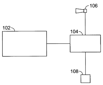
Figure 1 is a block diagram of an exemplary vehicle control system;
Figure 2 is a flow chart of an exemplary method for controlling a warning
signal using
the vehicle control system shown in Figure 1;
Figure 3 is a block diagram of an exemplary embodiment of the vehicle control
system shown in Figure 1; and
-2-
CA 02617670 2008-01-10
219582
Figures 4A, 4B, 4C, and 4D are timing diagrams of exemplary warning signal
sequences that may be used by the vehicle control system shown in Figure 3.
DETAILED DESCRIPTION OF THE INVENTION
Many specific details of certain embodiments of the invention are set forth in
the
following description in order to provide a thorough understanding of such
embodiments. One skilled in the art, however, will understand that the present
invention may have additional embodiments, or that the present invention may
be
practiced without several of the details described in the following
description.
Figure 1 is a block diagram of an exemplary embodiment of a vehicle control
system
100 that may be used with a locomotive to activate a warning signal. Although,
control system 100 is described with respect to a locomotive, as will be
appreciated by
one of ordinary skill in the art, control system may be used with any vehicle
that is
required to activate a warning signal while traveling through a warning area.
Moreover, although control system 100 is described with respect to activating
a
warning signal, as will be appreciated by one of ordinary skill in the art,
control
system may be used to activate any function of a vehicle.
In the exemplary embodiment, vehicle control system 100 includes a warning
device
102, a signaling system 104, and a horn 106. Further, in the exemplary
embodiment,
control system 100 also includes at least one indicator 108 such as, but not
limited to,
a light, a speaker, and/or a seat vibrator. Specifically, in the exemplary
embodiment,
warning device 102, signaling system 104, horn 106, and indicator 108 are each
electronically coupled. However, as will be appreciated by one of ordinary
skill in the
art, any of warning device 102, signaling system 104, horn 106, and/or
indicator 108
may have any configuration that enables control system 100 to operate as
described
herein.
In the exemplary embodiment, warning device 102 is at least one of, but is not
limited
to being, an imaging device, a bar code scanner, and/or a radio-frequency tag.
In an
alternative embodiment, control system 100 does not include warning device
102, but
rather, a whistle post is positioned along a track upon which the locomotive
is
-3-
CA 02617670 2008-01-10
219582
traveling. In the exemplary embodiment, signaling system 104 also includes a
processor 110. As used herein, the term "processor" is not limited to just
those
integrated circuits referred to in the art as processors, but broadly refers
to computers,
processors, microcontrollers, microcomputers, programmable logic controllers,
application specific integrated circuits, and other programmable circuits. The
processor may be part of a computer that may include a device, such as, a
floppy disk
drive or compact disc-read-only memory (CD-ROM) drive, for reading data from a
computer-readable medium, such as a floppy disk, a CD-ROM, a magneto-optical
disk (MOD), or a digital versatile disc (DVD).
During operation, in the exemplary embodiment, warning device 102 provides an
indication when the locomotive is within a predetermined distance to a warning
area.
Specifically, signaling system 104 activates when the locomotive is within the
predetermined distance of device 102. In one embodiment, warning device 102
activates signaling system 104. In an alternative embodiment, an engineer is
signaled
by indicator 108 visually, aurally, and/or tactilely to activate signaling
system 104.
Upon activation, and as described in more detail below, signaling system 104
determines when horn 106 should sound.
Figure 2 is a flow chart of an exemplary method 200 for use in controlling a
warning
signal using vehicle control system 100. In the exemplary embodiment, the
method
200 includes identifying 202 a trigger point that indicates when to activate
signaling
device 104. In one embodiment, the trigger point is identified by warning
device 102.
For example, the trigger point may include a radio-frequency tag, a readable
bar code
that is recognized by a bar code scanner, and/or an image marker that is
viewed by an
imaging device. In another embodiment, the trigger point includes a whistle
post or
other indicator of a road crossing that is designed to be viewed by the
engineer.
Vehicles, such as a locomotive for example, are required to comply with local,
state,
and or federal regulations with respect to sounding their horn when
approaching a
road crossing. Accordingly, whether a warning signal is required is determined
204
and if not required, then method 200 loops back to identify 202 the next
whistle
board. A warning signal may not be required in certain instances even though
the
-4-
CA 02617670 2008-01-10
219582
vehicle has passed a marker. For example, regulations may prohibit a warning
signal
at certain times of the day. Additionally, a warning signal may not be
required during
switching operations when the vehicle such as a locomotive may pass a marker
several times at a low speed to accomplish a switching operation. Moreover, a
warning signal may not be required at each crossing when a plurality of
crossings are
situated in close proximity.
If a warning signal is required, and because regulations vary depending on the
particular crossing being approached, the applicable regulation associated
with the
identified marker is determined 206. Next, signaling system 104 is activated
208. For
example, in one embodiment, warning device automatically activates signaling
system
104 upon determining that a warning signal is required. In another embodiment,
warning device activates indicator 108 to alert the engineer to manually
activate
signaling system 104. Specifically, indicator 108 alerts the engineer using at
least one
of a visual, aural, and tactile indication. In a further embodiment, the
engineer
recognizes the trigger point, manually determines whether a warning signal is
required, and then activates signaling system 104. In another embodiment, as
the
locomotive passes the trigger point, a local system transmits a signal that
activates
signaling system 104. In yet another embodiment, as the locomotive passes the
trigger point, a database of predetermined locomotive locations transmits a
signal that
activates signaling system 104.
Upon activation, signaling system 104 begins a warning signal sequence.
Specifically, signaling system 104 first determines 210 a speed of the
vehicle.
Further, in one embodiment, the speed is determined using the imaging device
as
described in further detail below. In alternative embodiments, the speed of
the vehicle
may be determined using tachometers connected to the wheels or other members
of
the drive train, electrical tachometers receiving signals from the vehicle
engine, global
positioning satellite systems, and/or other speed determining subsystems.
Next, signaling system 104 determines 212 a timing of the warning signal based
on
the appropriate regulations. In particular, signaling system 104 determines
how long
the warning signal should sound. For example, in one embodiment, the
applicable
-5-
CA 02617670 2008-01-10
219582
regulation may require horn 106 to sound for 15-20 seconds prior to the
vehicle
entering a crossing. In another embodiment, signaling system 104 may determine
a
number of blasts that should sound and an appropriate length of each blast.
Based on
the required timing of the blasts and the speed of the vehicle, an initiation
point for
sounding horn 106 is determined 214. Specifically, the initiation point is
determined
to ensure that the horn sounds for the applicable time prior to the vehicle
entering the
crossing. Further, in one embodiment, the initiation point is determined to
enable the
horn to sound prior to the vehicle entering the crossing and to ensure it
sounds while
the vehicle travels through the crossing.
In the exemplary embodiment, signaling system 104 determines 216 if the
locomotive
is required to change speeds. For example, if the speed of the locomotive and
the
location of the initiation point would cause horn 106 to sound after the
locomotive has
passed through the warning area, signaling system 104 changes 218 the speed of
the
locomotive by increasing its speed. Alternatively, if the speed of the
locomotive and
the location of the initiation point would cause horn 106 to stop sounding
before the
locomotive has passed through the warning area, signaling system 104 changes
218
the speed of the locomotive by decreasing its speed. After the locomotive
changes
speeds, signaling system 104 again determines 210 the speed of the locomotive
an
repeats steps 212, 214, and 216.
Further, in the exemplary embodiment, signaling system 104 determines 220 if
the
length of warning signal needs to be changed. Specifically, the regulations
may
dictate that the length of the warning signal should be between 15 and 20
seconds.
Accordingly, the length of the signal may be changed within this range. For
example,
if the speed of the locomotive, the location of the initiation point, and the
timing of
the signal would cause horn 106 to sound after the locomotive has passed
through the
warning area, signaling system 104 changes 222 the timing of the signal by
decreasing the timing. Alternatively, if the speed of the locomotive, the
location of
the initiation point, and the timing of the signal would cause horn 106 to
stop
sounding before the locomotive has passed through the warning area, signaling
system 104 changes 222 the timing of the signal by increasing the timing.
After
-6-
CA 02617670 2008-01-10
219582
signaling system 104 changes the timing of the signal, system 104 repeats the
determination 214 of the initiation point of the signal and repeats step 218.
When the locomotive passes the initiation point, horn 106 is sounded 224. In
one
embodiment, horn 106 is automatically sounded by signaling system 104 when the
locomotive passes the initiation point. In another embodiment, indicator 108
alerts
the engineer that the initiation point is approaching. Specifically, indicator
108 alerts
the engineer using, for example, at least one of a visual, aural, and tactile
indication.
In one embodiment, horn 224 is sounded for the applicable time as the
locomotive
approaches the crossing, in accordance with the applicable regulation. In
another
embodiment, horn 224 is sounded for the applicable time as the locomotive
approaches the crossing and as the locomotive travels through the crossing, in
accordance with the applicable regulation. After the warning signal sequence
is
complete and horn 224 is sounded, control system 100 is reset to identify the
next
trigger point.
Figure 3 is a block diagram of an exemplary embodiment of vehicle control
system
100. Specifically, Figure 3 illustrates a control system 300 that includes an
imaging
system as its warning device 102. As will be appreciated by one of ordinary
skill in
the art, elements of control system 300 that are the same as elements of
control system
100, shown in Figure 1, are identified using the same reference numerals.
Figures 4A,
4B, 4C, and 4D illustrate timing diagrams of exemplary warning signal
sequences that
may be used by control system 300. Although Figures 4A-4D are described with
respect to control system 300, as will be appreciated by one of ordinary skill
in the art,
the timing diagrams illustrated in Figures 4A-4D, with modification, can also
apply to
any embodiment of control system 100.
In the exemplary embodiment, warning device 102 includes a data preservation
programming and management system 302, an imaging device 304, and an image
processor 306. Data preservation programming and management system 302 is
electronically coupled to signaling system 104. Imaging device 304 is
typically aimed
forwardly towards the direction of travel of the vehicle. Further, in one
embodiment,
data preservation programming and management system 302 is communicatively
-7-
CA 02617670 2008-01-10
219582
coupled to an image processor 306. Image processor 306 may be a stand alone
unit,
or alternatively may be incorporated as a function of data preservation
programming
and management system 302. Image processor 306 receives image data from
imaging
device 304, through data preservation programming and management system 302,
and/or to receives image data directly from imaging device 304.
In operation, imaging device 304 captures image data of wayside objects, such
as
whistle board 308 for example, and transmits such images to image processor
306 or
data preservation programming and management system 302. Image processor is
programmed to compare the captured image to an image of a known object stored
in
data preservation programming and management system 302 to identify the
objects in
the captured image. Objects may be identified, for example, using symbols on
the
object, by an outline of the object, by a color scheme associated with the
object, other
image processing methodologies, or combinations thereof. For example, a
whistle
board 308 may be identified using an outline of its shape, by the symbol "W"
appearing on a surface of whistle board 308, or through a combination of these
or
other features. When a match is made between an object in a captured image and
an
object in a stored image, image processor 306 utilizes the identification of
the object
in a logic circuit to activate signaling system 104.
In one embodiment, image processor 306 also determines other parameters from
received images, such as, but not limited to, a speed of the locomotive as it
passes an
object. In such a case, the object does not need to be identified; but rather
the object
merely needs to appear in order in sequential images that are captured at
predetermined
time intervals. For example, image processor 306 selects a pattern of a first
image
that is generated at a first time and locates the same pattern in a second
subsequent
image that is generated at a second time. Image processor determines a
distance
traveled by determining elapsed time and/or differences between the first and
second
times. Image processor 306 then determines a speed of the locomotive using the
determined distance and also utilizing the physical differences in the
captured images.
In another embodiment, image processor 306 determines any weather and or
lighting
conditions that may affect a requirement for sounding of the warning signal.
For
-8-
CA 02617670 2008-01-10
219582
example, some warning signal sequences may be necessary in various weather
conditions such as fog, smoke, darkness, or blizzard conditions that may
affect
visibility.
Figure 4A is a side view of a section of track 400 that includes warning area
402, such
as a road crossing. In the exemplary embodiment, a whistle board 308 is
positioned
approximately one quarter mile away from warning area 402. In Figure 4A,
direction
406 indicates the direction of travel of the locomotive approaching the
warning area
402.
In use, image processor 306 is programmed to automatically identify a passing
object,
such as the whistle board 308, and to automatically calculate the speed of the
locomotive as the locomotive passes the whistle board 308. Since, the distance
between the whistle board 308 and the warning area 402 is generally set by
federal
guidelines, programming and management system 302 utilizes the information
received from image processor 306 used in identifying the whistle board 308,
and the
predetermined distance between the whistle board 308 and the warning area 402,
to
generate a warning signal sequence.
As discussed above, under certain federal and state guidelines, a locomotive
engineer
may be required to initiate a warning signal, e.g. sound horn 106, when the
locomotive passes whistle board 308. However, the position of the whistle
board 308
is based on the train traveling at the maximum speed at that location.
However, when
a train is traveling at a speed that is less than the maximum speed,
programming and
management system 302 is configured to generate a warning signal sequence
based on
the speed of the locomotive as the locomotive passes whistle board 308.
Figure 4B is an exemplary timing diagram for a first exemplary warning signal
sequence 408 generated by programming and management system 302 when the
locomotive is traveling at approximately sixty miles per hour. In such an
embodiment, sequence 408 includes two short blasts 410 and 412 and a long
blast
414. The length of each blast may be determined by elapsed time, or may be
determined by a change in distance from the start of each blast to the finish
of each
-9-
CA 02617670 2008-01-10
219582
blast. Additionally, the timing of sequence 408 may be determined by elapsed
time,
or may be determined by a change in distance from the start of each blast to
the finish
of each blast. Because of the speed of the locomotive and the requirements of
timing
the warning signal by regulation, there is no time delay between the
locomotive
passing whistle board 308 and the initiation of short blast 410. Specifically,
because,
in this example, the locomotive is traveling at approximately sixty miles per
hour as
determined by programming and management system 302, the whistle board 308 is
positioned approximately one-quarter of a mile from warning area 402 by
regulation,
and the horn 104 must be sounded for fifteen seconds from the locomotive
entering
warning area 402, programming and management system 302 calculates that the
warning signal sequence 408 should be initiated when the locomotive passes
whistle
board 308 as identified by image processor 306.
Figure 4C is an exemplary timing diagram for a second warning signal sequence
420
generated when the locomotive is traveling at approximately forty miles per
hour.
Sequence 420 includes two short blasts 422 and 424 and a long blast 426.
Because of
the speed of the locomotive and the requirements of timing the warning signal
by
regulation, there is a time delay 428 between the locomotive passing whistle
board
308 and the initiation of short blast 422. The length of time delay 428
ensures that the
start of sequence 420 does not occur prior to the regulated maximum time prior
to
warning area 402. In this case, since the speed of the locomotive is
approximately
forty miles per hours as determined by programming and management system 302,
the warning signal sequence 420 will be activated when the locomotive is
approximately 880 feet from warning area 402 such that horn 104 is activated
fifteen
seconds prior to the locomotive entering warning area 402.
Figure 4D is an exemplary timing diagram for a third warning signal sequence
430
generated when the locomotive is traveling at approximately twenty miles per
hour.
Sequence 430 includes two short blasts 432 and 434 and a long blast 436.
Because of
the speed of the locomotive and the requirements of timing the warning signal
by
regulation, there is a time delay 438 between the locomotive passing whistle
board 308
and the initiation of short blast 432. The length of time delay 438 ensures
that the start
-10-
CA 02617670 2008-01-10
219582
of sequence 430 does not occur prior to the regulated maximum time prior to
warning
area 402. Although the blasts in Figures 4B, 4C, and 4D appear to have
differing
lengths, the blasts in Figures 4B, 4C, and 4D have the same length. The
apparent
difference in length is due to the scale of the figures being in distance
rather than time.
The foregoing description of the exemplary embodiments of the invention are
described for the purposes of illustration and are not intended to be
exhaustive or
limiting to the precise embodiments disclosed. Many modifications and
variations are
possible in light of the above teaching. It is intended that the scope of the
invention
be limited not with this detailed description, but rather by the claims
appended hereto.
In one embodiment, a method for automatically sounding a vehicle warning is
provided. The method includes determining when the vehicle is within a
predetermined distance to a warning area, and determining a speed of approach
of the
vehicle to the warning area. The method also includes determining an
initiation point
to activate the vehicle warning based on the speed of approach of the vehicle,
and
sounding the vehicle warning at the initiation point.
In the exemplary embodiment, the method also includes activating a signaling
system
when the vehicle is within the predetermined distance. The signaling system is
configured to determine the speed of approach, determine the initiation point,
and
sound the vehicle warning. In one embodiment, the signaling system is manually
activated when the vehicle passes a whistle post positioned at the
predetermined
distance from the warning area. In another embodiment, the signaling system is
activated when at least one of an imaging device, a bar code scanner, and a
radio
frequency tag indicates that the vehicle is within the predetermined distance
to the
warning area. For example, in one embodiment, the image processor views the
path
of the vehicle in the direction of travel to identify an image marker
identifying the
predetermined distance to the warning area. Further, sequential images of the
image
marker are generated to determine the speed of the vehicle.
In one embodiment, the method also includes generating at least one of a
visual, aural,
and a tactile indication when the vehicle is within the predetermined
distance.
-11-
CA 02617670 2008-01-10
219582
Further, in the exemplary embodiment, the vehicle is a locomotive and the
method
includes sounding the vehicle warning as a locomotive approaches and crosses a
railroad crossing. Moreover, in one embodiment, the method includes
identifying an
appropriate regulation governing the operation of the vehicle warning, and
generating
the vehicle warning based on the regulation identified. In such an embodiment,
the
method also includes indicating a change in the speed of the vehicle that is
necessary
to generate the vehicle warning based on the identified regulation.
The above-described methods and systems for automatically sounding a vehicle
warning are cost-effective and highly reliable. The system permits
automatically
determining the boundaries of area when a warning signal is required to be
sounded
by regulation, alerting the user to the approaching need to sound the warning
signal,
and in one embodiment, to sound the warning signal in accordance with the
regulatory
mandate without user input. Accordingly, the methods and systems described
herein
facilitate operation of data recorders in a cost-effective and reliable
manner.
Exemplary embodiments of systems and methods for automatically activating
train
warning devices are described above in detail. The systems and methods
illustrated
are not limited to the specific embodiments described herein, but rather,
components
of the system may be utilized independently and separately from other
components
described herein. Further, steps described in the method may be utilized
independently and separately from other steps described herein.
While the invention has been described in terms of various specific
embodiments,
those skilled in the art will recognize that the invention can be practiced
with
modification within the spirit and scope of the claims.
-12-