Note: Descriptions are shown in the official language in which they were submitted.
CA 02617678 2008-02-01
WO 2007/016517 PCT/US2006/029806
TITLE: METHODS, DATA STRUCTURES, AND SYSTEMS FOR CLASSIFYING
MICROPARTICLES
BACKGROUND OF THE INVENTION
1. Field of the Invention
This invention generally relates to methods, data structures, and systems for
classifying
microparticles. Certain embodiments relate to methods for classifying a
microparticle using data
acquired for the microparticle in combination with a lookup table and one or
more algorithms
associated with different microparticle classifications.
2. Description of the Related Art
The following descriptions and examples are not admitted to be prior art by
virtue of their
inclusion within this section.
Generally, flow cytometers provide measurements of fluorescence intensity and
other
optical properties of microparticles (e.g., laser excited polystyrene beads)
as they pass linearly
through a flow chamber. A variety of measurements may be performed including,
but not limited
to, the level of light scattered by the microparticle, the measure of
electrical impedance of the
microparticle, and one or more measurements of fluorescence of the
microparticle. These and
any other measurements may be performed by different "channels" of the system
(e.g., reporter
channels and classification channels), which include a detector and possibly
other components
(e.g., optical components, electronic components, etc.) coupled to the
detector.
Often microparticles may be classified by their one or more of their
measurement values,
each value corresponding to a different "parameter" (examples of which are
noted above) of the
microparticle. For example, one common method of classifying microparticles is
to graph
measurement values in a classification space (e.g., a bitmap) and determine if
the graphed
location is positioned within a predetermined area of the classification space
that corresponds to
a particular classification of microparticles. Such a process is referred to
herein as a bitmap-
based conventional classification method. Unfortunately, the process has its
drawbacks. In
particular, graphical representation of the classification schemes using this
methodology is not
easily extended to more than two parameters.
One specific problem encountered in extending the aforementioned
classification method
to more than two parameters is that the size of the graph scales linearly with
the resolution of
1
CA 02617678 2008-02-01
WO 2007/016517 PCT/US2006/029806
each parameter used to classify the microparticle, and exponentially according
to the number of
parameters. For example, if a two-dimensional bitmap has a combined size of
100 units (i.e., 10
units x 10 units), then a three-dimensional bitmap will have a combined size
of 1,000 units and a
four-dimensional bitmap will have a combined size of 10,000 units. Such
exponential increases,
in some cases, may be completely prohibitive for some system memory capacity.
Also, it is
noted that parameters of data acquired for microparticles by flow cytometry
often have a
combined size that is much higher than 100 possible units and typically
include three or more
parameters. Furthermore, creating bitmaps in more than two dimensions is much
more difficult
than in two dimensions, since representing a "more than two"-dimensional
bitmap in a two-
dimensional structure such as a piece of paper or a computer display requires
some sacrifice in
fidelity to the actual data.
Accordingly, it would be desirable to develop methods, data structures, and
systems for
classifying particles that can be easily extended beyond more than two
parameters, that do not
expand memory usage exponentially with each additional parameter, and are
structured to
minimize the processing time in which particle classification is performed.
SUMMARY OF THE INVENTION
The following description of various embodiments of methods, data structures,
and
systems is not to be construed in any way as limiting the subject matter of
the appended claims.
An embodiment of a computer-implemented method includes acquiring a first set
of data
corresponding to measurable parameters of a microparticle and identifying a
location of a look-
up table to which the first set of data corresponds, wherein the look-up table
is framed by values
associated with at least one of the measurable parameters. Furthermore, the
method includes
- determining whether the first set of data fits one or more predefined
algorithms, wherein each of
the one or more predefined algoritluns is respectively indicative of a
different microparticle
classification of a plurality of microparticle classifications associated with
the identified location
of the look-up table. The method further includes classifying the
microparticle within at least
one predefined categorization based upon the determination of whether the
first set of data fits
the one or more predefined algorithms. This embodiment of the method may
include any other
steps described herein.
An embodiment of a system includes a processor, a look-up table framed by one
or more
measurable parameters of microparticles, and program instructions which are
executable by the
processor for performing the steps of the aforementioned computer-implemented
method. This
2
CA 02617678 2008-02-01
WO 2007/016517 PCT/US2006/029806
embodiment of a system may be fi.trther configured as described herein. In
addition, the data
structure of the look-up table may be further configured as described herein.
Another embodiment of a computer-implemented method includes acquiring a first
set of
data corresponding to measurable parameters of a microparticle and creating a
second data set
including one or more umbrella values respectively correlating to one or more
distinct values of
the first set of data. Each of the umbrella values represents a range of
possible values for a
corresponding measurable parameter. The method further includes identifying a
location of a
look-up table to which the second data set corresponds, wherein the look-up
table is framed by
umbrella values of at least one of the measurable parameters. In addition, the
method includes
determining whether the first set of data fits a predefined algorithm
indicative of a microparticle
classification associated with the identified location of the look-up table
and classifying the
microparticle within at least one predefined categorization based upon such a
determination. This
embodiment of the method inay include any other steps described herein.
BRIEF DESCRIPTION OF THE DRAWINGS
Other objects and advantages of the invention will become apparent upon
reading the
following detailed description and upon reference to the accompanying drawings
in which:
Fig. 1 is a two-dimensional graph that includes classification spaces
corresponding to
populations of which microparticles may be members;
Fig. 2 illustrates a flow chart of a method for classifying a microparticle
Figs. 3 and 4 are schematic diagrams illustrating different embodiments of a
lookup table;
and
Fig. 5 is a schematic diagram illustrating one embodiment of a system
configured to
classify microparticles.
While the invention is susceptible to various modifications and alternative
forms, specific
embodiments thereof are shown by way of example in the drawings and will
herein be described
in detail. It should be understood, however, that the drawings and detailed
description thereto are
not intended to limit the invention to the particular form disclosed, but on
the contrary, the
intention is to cover all modifications, equivalents and alternatives falling
within the spirit and
scope of the present invention as defined by the appended claims.
3
CA 02617678 2008-02-01
WO 2007/016517 PCT/US2006/029806
DETAILED DESCRIPTION OF THE PREFERRED EMBODIMENTS
The term "microparticle" is used herein to generally refer to particles,
microspheres,
polystyrene beads, quantum dots, nanodots, nanoparticles, nanoshells, beads,
microbeads, latex
particles, latex beads, fluorescent beads, fluorescent particles, colored
particles, colored beads,
tissue, cells, micro-organisms, organic matter, non-organic matter, or any
other discrete
substrates or substances known in the art. Any of such terms may be used
interchangeably
herein. The methods, data structures, and systems described herein may be used
for classification
of any type of microparticles. In some cases, the methods, data structures,
and systems described
herein may be particularly used for microparticles serving as vehicles for
molecular reactions.
Exemplary molecular reaction microparticles which are used in flow cytometry
include xMAP
microspheres, which may be obtained commercially from Luminex Corporation of
Austin,
Texas.
As used herein, the term "classification" is generally defined as determining
the identity
of individual microparticles in a sample. The identity relates to the
population to which
individual microparticles belong. Such classification is of particular
importance since often a
sample will be analyzed with multiple, different populations of microparticles
in a single
experiment of the sample. In particular, different populations of
microparticles typically have at
least one different characteristic such as the type of substance coupled to
the microparticles
and/or the quantity of substance(s) coupled to the microparticles such that
the presence of
2o different types and/or quantities of analytes witliin the sample can be
detected and/or quantified
in a single experiment. To interpret the measurement results, the identity or
classification of
individual microparticles in the sample may be determined such that the
measurement values
may be correlated to the properties of the individual microparticles. In this
manner, the
measurement values associated with the different populations of microparticles
can be
distinguished and respectively attributed to the analytes of interest.
Systems that may be configured to perform one or more of the processes
described herein
include, but are not limited to, the Luminex 100 Tm, the Luminex HTS, the
Luminex
l 00E, Luminex 200 Tm, and any fi.irther add-ons to this family of products
that are available
from Luminex Corporation of Austin, TX. One general example of such systems is
described
further herein in reference to Fig. 5. However, it is to be understood that
the methods, data
structures, and systems described herein may use or may be configured to use
microparticle data
acquired by any measurement system. Examples of measurement systems include
flow
cytometers and fluorescent imaging systems. In addition, although various
parameters are
4
CA 02617678 2008-02-01
WO 2007/016517 PCT/US2006/029806
described herein that can be used for microparticle classification, it is to
be understood that the
embodiments described herein may use any measurable parameter of
microparticles that can be
used to distinguish different populations of the microparticles. Furthermore,
the methods, data
structures, and systems described herein are not limited to microparticle
classification. In
particular, the embodiments described herein may be equally applied to
determining other
parameters of microparticles such as, but not limited to, the identity or
quantity of a reaction
product present on the microparticles or in the sample.
Turning to the drawings, Fig. 1 illustrates an exemplary classification space
which may be
used to classify microparticles in a conventional manner. The process includes
acquiring data for
microparticles using a flow cytometer or other suitable device and using the
data for
classification. In particular, the method typically includes plotting
measurement data for two
parameters on a graph having two axes each corresponding to a different
parameter (such as
shown by axis titles Parameter 1 and Parameter 2 in Fig. 1). The graph also
includes different
classification areas (e.g., areas 1-12 shown in Fig. 1), each corresponding to
a different
population of microparticles. The location of a data point in the graph
corresponding to the
measured parameters of a microparticle determines the microparticle's
membership in one of the
populations. For example, as shown in Fig. 1, a single data point
corresponding to values of two
parameters acquired for a single microparticle is shown by an asterisk (*).
Because the data point
lies within the boundaries of area 9 (represented in the graph as the cross-
hatched space labeled
with the numeral 9), the microparticle is classified as being a member of the
population
corresponding to area 9. If the data point instead is located in the white
space in the graph
outside of areas 1-12, then the microparticle is classified as not being a
member of any area and
is thereby not classified as belonging to any population.
The methods and systems described herein perform microparticle classification
in a
manner different than that described above. In particular, the embodiments
described herein
utilize a look-up table (LUT) to narrow a search of classification populations
to which a
microparticle may belong and subsequently process data acquired for the
microparticle in one or
more predefined algorithms associated with an identified location of the look-
up table.
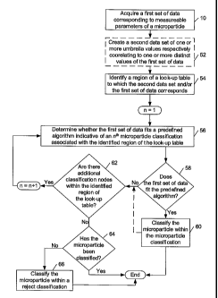
A flowchart outlining exemplary steps of such a method is shown in Fig. 2. As
described
in more detail below, the algorithms which are used to define the
microparticles classifications
may, in some embodiments, be complex (e.g., the algorithms may relate more
than 2
measurement parameters of a microparticle) and, therefore, may be best
implemented through a
computer. As such, the systems and storage mediums described herein, such as
described in
5
CA 02617678 2008-02-01
WO 2007/016517 PCT/US2006/029806
reference to Fig. 5, may include program instructions which are executable by
a processor and
which are configured to perform the processes depicted in Fig. 2. Therefore,
the methods
described in reference to Fig. 2 may be referred to as "computer-implemented
methods" and,
thus, the terms "method" and "computer-implements method" may be used
interchangeably
herein. It is noted that the computer-iinplemented methods and program
instructions of the
systems described herein may, in some cases, be configured to perform
processes other than
those associated with microparticle classification and, therefore, the
computer-implemented
methods and program instructions of systems described herein are not
necessarily limited to the
depiction of Fig. 2. Furthermore, although the steps described herein are
described with respect
to classification of "a microparticle," it is to be understood that any or all
of the steps of the
method embodiments described herein may be performed for one or more
microparticles in a set
(e.g., some or all of the microparticles in a set).
As shown in Fig. 2, the metliods and program instructions of the systems
described herein
may include block 10 in which a first set of data corresponding to measurable
parameters of a
microparticle. Such a data set may be those obtained by a flow cytometer or
other suitable
device. The data may be acquired by measuring the data for individual
microparticles using the
flow cytometer or by requesting and receiving the data from the flow
cytometer. In this manner,
the method may be performed by the measurement system itself (e.g., by a
processor of the
measurement system) or by a system (e.g., a processor of a stand-alone
computer system)
coupled to the measurement system. hi any case, the data set may, in some
embodiments,
include measurements of several different parameters including but not limited
to those used to
classify the microparticle. For example, the first set of data may include
measurements of
fluorescence, light scatter, electrical impedance, or any otlier measurable
property of the
microparticle.
In some embodiments, the method and program instructions of the systems
described
herein may continue to block 52 as shown in Fig. 2 to create a second data set
having one or
more umbrella values respectively correlating to one or more distinct values
of the first set of
data. Such a step may advantageously reduce the resolution of the measurements
within the first
set of data to coincide with the scale of measurement parameter values used to
frame a look-up
table. As described in more detail below, the look-up table is a data
structure used to narrow the
search of a microparticle classification to which to categorize the
microparticle. A look-up table
framed by values of relatively low resolution may allow the table to be sized
with a smaller
number of units which, in turn, limit the size of the memory needed to
characterize the table.
6
CA 02617678 2008-02-01
WO 2007/016517 PCT/US2006/029806
Limiting the size of the memory for the look-up table may be advantageous in
some cases,
particularly for reducing the cost of a system. Although creating a second set
of data with values
of reduced resolution relative to corresponding values of the first set of
data may be
advantageous in some cases, it is noted that creation of the second data set
in the methods
described herein is optional and, consequently, block 52 has been outlined by
a dotted line. In
particular, the methods described herein do not necessarily need to include
the creation of a data
set witlz reduced resolution values. Rather, the method may omit block 52 and
continue to block
54 to identify a location of a look-up table to which the first set of data
corresponds as described
in more detail below.
In some embodiments, the creation of the second data set may include
replicating one or
more values of the first set of data and reducing the resolution of one or
more of the replicated
values. In some cases, the resolution of all of the replicated values may be
reduced. In other
cases, however, less than all of the replicated values may be reduced. As
such, although the
second data set is created to include values of reduced resolution, the second
data set is not
necessarily restricted from also including values which have not been reduced
in resolution (i.e.,
relative to corresponding values in the first set of data). For example, in
some embodiments,
only one of the measurement parameters framing the look-up table may include a
scale of low
resolution and, therefore, it may only be pertinent to reduce the resolution
of replicated values
associated with that measurement parameter. Other scenarios may warrant
reducing the
resolution of a fraction of the replicated values and, therefore, the methods
described herein are
not necessarily limited to such an example.
In some embodiments, the second data set may include values associated with
all of the
values acquired for the first data set. In other embodiments, the second data
set may include
fewer values than those acquired for the first set of data. For instance, the
method and program
instructions described herein may, in some embodiments, be configured to
create a second data
set with only values associated with measurement parameters framing the look-
up table. Other
scenarios may warrant the second data set to include a fraction of the values
acquired for the first
set of data and, therefore, the methods described herein are not necessarily
limited to the
aforementioned example.
In any case, the values of reduced resolution within the second data set
(i.e., relative to
the corresponding values in the first set of data) may be referred to herein
as "umbrella values".
Alternatively stated, the term "umbrella value" may generally refer to a value
representing a
range or span of possible values for a corresponding measurement parameter. In
contrast, values
7
CA 02617678 2008-02-01
WO 2007/016517 PCT/US2006/029806
wliose resolution has not been reduced, such as those in the first set of
data, may be referred to
herein as "distinct values" and/or "measurement values". In some cases,
creating the second data
set may include rounding one or more replicated values of the first set of
data to the nearest
integer value. For example, measurement values of 1.07 and 1.09 may be both
represented by an
umbrella value of 1.1. In this manner, each of the rounded values may
generally represent a
range of possible measurement values less than, greater, or midway from the
rounded integer to
the next integer. For instance, in the aforementioned embodiments, an umbrella
value of 1.1 may
represent measurement values between 1.01 and 1.10. In other embodiments, an
umbrella value
of 1.1 may represent measurement values between 1.10 and 1.19 or measurement
values between
1.05 and 1.14. In general, the ranges of measurement values an umbrella value
may represent
may depend on the design specifications set up for the method and, in some
embodiments, the
design specifications of the program instructions configured to perform such a
process step.
In other cases, the second data set may include umbrella values representing
ranges of
integers for a measurement parameter. For example, as shown in Table 1,
discrete values
associated with Parameter 1 in a first set of data may be referenced by any
one of four umbrella
values in a second data set. It is noted that Table 1 is merely an exemplary
correlation of distinct
and umbrella values. The range of distinct values and the number of selected
umbrella values for
a measurement value may differ among different set ups of methods and program
instructions.
Table 1
Distinct Umbrella
Measured Values of
Values of Parameter 1
Parameter 1
1.00-25.99 1
26.00-50.99 2
51.00-75.99 3
76.00-100.00 4
Furthermore, although the ranges of discrete values shown in Table 1 are
equally
segregated among the umbrella values (i.e., 25 discrete values for each
umbrella value), it is to be
understood that each umbrella value may correspond to any number of discrete
values. In other
words, the ranges of distinct values respectively associated with umbrella
values for a
measurement parameter may not necessarily be uniform. In some cases, the
degree to which each
8
CA 02617678 2008-02-01
WO 2007/016517 PCT/US2006/029806
discrete value is reduced in resolution may vary depending on, for example,
characteristics of the
microparticle classifications, characteristics of the microparticle
populations, and/or
characteristics of individual microparticles in the populations.
In any case, the resolution of values corresponding to different measurement
parameters
may, in some embodiments, be reduced in a similar manner for the second data
set. In particular,
distinct values corresponding to different measurement parameters may be
either rounded to the
nearest integer or assigned values for integer ranges to create the second
data set. In other
embodiments, distinct values corresponding to different measurement parameters
may be
reduced in different manners for the second data set. In any case, the number
of umbrella values
for different measurement parameters may be the same or different.
Turning back to Fig. 2, the methods and program instructions described herein
may be
configured to continue to block 54 to identify a location of a look-up table
to which the second
data set and/or the first set of data corresponds. More specifically, if block
52 is included in the
process, then a location of the look-up table to which the second data set
corresponds will be
identified with respect to block 54. It is noted that since the second data
set includes values
corresponding to measured values in the first set of data, the location of the
look-up table
identified with respect to block 54 in such an embodiment will correspond to
the first set of data
as well as the second data set. However, in embodiments in which block 52 is
omitted from the
process, the location of the look-up table identified with respect to block 54
will only correspond
to the first set of data since the second data set was not created.
In embodiments in which block 52 is omitted from the process, block 54 may
generally
include indexing the measured values from the first set of data which are
associated with the
parameters framing the look-up table, in effect locating a point as an
"identified location" within
the look-up table to which the first set of data corresponds. In some cases,
methods which
include block 52 may also be configured to locate a point as an "identified
location" within the
look-up table. In particular, if the scale resolution for each of the
measurement parameters
framing the look-up table is the same as the resolution of the corresponding
values in the second
data set, then block 54 may include indexing such values from the second data
set to identify a
location or, more specifically, a point within the look-up table to which the
second data set
corresponds. For example, if the umbrella values within the second data set
represent integers
rounded from the distinct values of the first set of data and the scale
resolution of the
corresponding measurement parameter/s framing the look-up table is at least
high enough to
distinguish individual integers, then indexing such values will culminate in a
point in the look-up
9
CA 02617678 2008-02-01
WO 2007/016517 PCT/US2006/029806
table. It is noted that such pinpointing within the look-up table may also
include indexing
distinct values from the second data set as long as the scale resolution of
the corresponding
measurement parameter/s are the saine as the distinct values.
An exemplary embodiment of a loolc-up table in which points may be identified
as
locations which correspond to values of a second data set is shown in Fig. 3.
In particular, Fig. 3
illustrates an exemplary look-up table framed by two measurement parameters,
the scales of
which range from 0 to 100 and are limited to integer values. It is noted that
a variety of
configurations for look-up tables may be used for the methods described
herein. In particular, as
noted above, the scales of the measurement parameters framing a look-up table
may be discrete
values, integers, or values representing ranges of integers, depending on the
desired resolution.
In addition, the scales for the different measurement parameters framing the
look-up table may be
the same or different. Furthermore, the look-up tables described herein may be
framed by any
number of measurement parameters. As will be described in more detail below,
the methods
described herein may be particularly applicable for look-up tables framed by
more than two
measurement parameters. As such, look-up tables for the methods described
herein are not
necessarily limited to the depiction of the example in Fig. 3.
In general, identifying a location of the look-up table depicted in Fig. 3 may
include
indexing integer umbrella values associated with Parameters 1 and 2. As will
be described in
more detail below in reference to block 56, if an identified location
coincides with one of nodes
1-5, then an algorithm associated with the node may be processed with the
measured values of
the first set of data to determine whether the particle may be classified
within the microparticle
classification corresponding to the node. In contrast, if the identified
location does not coincide
one of nodes 1-5, then the particle will be categorized within a reject
classification. Such a
determination of classification for the methods described herein changes when
a coarse location
of a look-up table comprising multiple nodes is identified to correspond with
a set of data as
described in more detail below.
Regardless, narrowing the search for a microparticle classification to test
using the look-
up tables described herein may save time relative to iteratively processing
through each
microparticle classification of a sample to determine the classification of a
particle (which is also
described in more detail below). It is noted for clarification purposes that
nodes 1-5 in Fig. 3
signify different microparticle classifications with respect to the parameters
framing the look-up
table and, thus, are not necessarily identified locations of the look-up table
corresponding to a
CA 02617678 2008-02-01
WO 2007/016517 PCT/US2006/029806
first and/or second set of data. In addition, as will be described in more
detail below, nodes 1-5
may be larger or smaller than those depicted in Fig. 3.
As noted above, coarse locations of a look-up table may be identified as
corresponding to
a set of data for block 54. In particular, block 54 may include indexing
umbrella values which
represent ranges of integers in relation to a relatively low resolution scale
of the measurement
parameters framing a look-up table to identify a block location of the look-up
table. More
specifically, the scale of the look-up table may include a relatively low
resolution such that
values on the scale are correlated to rows and columns of the look-up table.
In such cases, the
size of the look-up tables for given=breadths of the measurement parameters
may be smaller than
those with integer value scales (such as shown in Fig. 3) and especially
relative to those with
scales which have not been reduced in resolution. As a consequence, memory
size of the look-up
tables may be reduced.
An exemplary look-up table in which coarse locations may be identified as
locations
which correspond to values of a second data set is shown in Table 2. In
particular, Table 2
illustrates an exemplary look-up table framed by two measurement parameters,
the scales of
which range from 1 to 4, each correlating to a different range of integers for
the respective
measurement parameters. The look-up table of Table 2 has only 161ocations in
comparison to,
for exanlple, 10,000 elements (100 x 100 units of each of the measurement
parameters) that may
be included in a full-resolution look-up table of the original values of the
two parameters in some
embodiments.
Table 2
4 No Node No Node No Node Node 5
N 3 No Node Node 3 Node 4 No Node
}~
2 No Node Node 1 No Node Node 2
1 No Node No Node No Node No Node
1 2 3 4
Parameter 1
As with the look-up table depicted in Fig. 3, the look-up table of Table 2 may
be used to
narrow the search for a microparticle classification to which a particle may
be categorized. In
particular, in some embodiments, some of the coarse locations may include a
node associated
11
CA 02617678 2008-02-01
WO 2007/016517 PCT/US2006/029806
with a microparticle classification and, therefore, the identification of a
location with a node may
facilitate further investigation as to whether the particle may be categorized
to the microparticle
classification. In particular, when an identified location includes a node, an
algorithm associated
with the node may be processed with the measured values of the first set of
data to determine.
whether the particle may be classified within the microparticle classification
corresponding to the
node. In contrast, if the identified coarse location does not include a node,
then the particle will
be categorized within a reject classification. For example, using the look-up
table of Table 2, if a
particular data point has umbrella values for Parameter 1 = 2 and Parameter 2
= 1(i.e., 2,1), the
method may determine that the data point is not a member of any node since the
coarse location
of the look-up table corresponding to these umbrella values of the parameters
is not associated
with any nodes. If instead a data point has umbrella values of (2,2), then the
method may process
the data point to determine whether it is a potential member of node 1 but not
of nodes 2-5.
Consequently, narrowing the search for a microparticle classification to test
using the look-up
table in Table 2 may save time relative to iteratively processing through each
of nodes 1-5 to
determine the classification of a particle.
The coarse locations including nodes 1-5 in Table 2 are outlined in bold to
distinguish
their presence relative to the coarse locations which do not include nodes. As
noted above, a
variety of configurations for look-up tables may be used for the methods
described herein and, as
such, a look-up table configured for identification of coarse locations is not
limited to Table 2. In
particular, the scales for the different measurement parameters framing the
look-up table may be
the same or different. Furthermore, the look-up tables described herein may
include any number
of scale values for each of the measurement parameters (i.e., they are not
limited to four values as
depicted in Table 2) and may be framed by any number of measurement
parameters. Moreover,
the number and distribution of nodes may vary within look-up tables described
herein. For
example, all coarse locations of a look-up table may include a node in some
embodiments.
In general, the number of nodes per coarse location may be used determine the
"resolution" of the look-up table. For example, a look-up table having no more
than one node
included in each coarse location, such as described in reference to Table 2,
has the highest useful
resolution. A look-up table having such resolution, however, may in some
embodiments be
relatively large. For instance, for a set of microparticles that includes
1,000 different
populations, a look-up table having no more than one node per coarse location
needs a minimum
of 1,000 coarse locations. In order to minimize the memory capacity needed to
represent so
12
CA 02617678 2008-02-01
WO 2007/016517 PCT/US2006/029806
many nodes, it may be advantageous to reduce the resolution of a look-up table
such that
multiple nodes are arranged within one or more coarse locations.
As such, another exemplary look-up table in which coarse locations may be
identified as
locations which correspond to values of a second data set is shown in Table 3.
Tn particular,
Table 3 illustrates an exemplary look-up table framed by two measurement
parameters, the scales
of which range from 1 to 4, each correlating to a different range of integers
for the respective
measurement parameters as in Table 2. Table 3 differs from Table 2, however,
by having some
coarse locations with multiple nodes (i.e., node sets). In particular, Table 3
illustrates four coarse
locations each with a plurality of nodes. A plurality of nodes within a single
coarse location is
referred to herein as a "node set." More specifically, Table 3 includes four
coarse locations with
Node Sets 1-4. Table 3 also includes one coarse location with a single node
referenced as Node
5 and 11 coarse locations with no nodes. Such a configuration may allow a look-
up table of a
given size to include a greater number of nodes, permitting a greater number
of microparticle
classifications to categorize a particle within a sample. In addition or
alternatively, as noted
above, a look-up table having multiple nodes within coarse locations may be
configured with
lower-resolution scales relative to look-up tables which only include one node
per coarse
location. As a consequence, memory size of such look-up tables may be reduced.
Table 3
4 No Node No Node No Node Node 5
c~ 3 No Node Node Set 3 Node Set 4 No Node
Q)
2 No Node Node Set 1 No Node Node Set 2
Cd
1 No Node No Node No Node No Node
1 2 3 4
Parameter 1
As shown in Table 3, some of the coarse locations of the look-up table may
include no
nodes or a single node. The coarse locations including nodes 1-5 in Table 3
are outlined in bold
to distinguish their presence relative to the coarse locations which do not
include nodes. As
noted above, a variety of configurations for look-up tables may be used for
the methods
described herein and, as such, a look-up table having multiple nodes within a
coarse location is
not limited to Table 3. In particular, the scales for the different
measurement parameters framing
13
CA 02617678 2008-02-01
WO 2007/016517 PCT/US2006/029806
the look-up table may be the same or different. Furthermore, the look-up
tables described herein
may include any number of scale values for each of the measurement parameters
(i.e., they are
not limited to four values as depicted in Table 3) and may be framed by any
number of
measurement parameters. Moreover, the number, size, shape, and distribution of
nodes may vary
within look-up tables described herein. For example, all coarse locations of a
look-up table may
include at least one node in some embodiments. In addition or alternatively,
nodes may overlap
including those within a single coarse location of a look-up table and those
of different coarse
locations. It is noted that if membership of a data point to one node is
mutually exclusive to
membership in another node, then the rules of each node may be defined to be
non-overlapping.
Fig. 4 illustrates yet another embodiment of a look-up table including
multiple nodes
arranged within coarse locations of the table. As with Table 3, Fig. 4
illustrates a look-up table
having some locations with no nodes, some locations with one node, and other
locations with
more than one node. Fig. 4 differs from Table 3 by illustrating that the
number, size, shape, and
distribution of nodes may vary between look-up tables as well as within a
single look-up table.
In addition, Fig. 4 illustrates nodes may overlap boundaries of coarse
locations and, therefore,
may be associate with multiple locations, such as shown for nodes 6 and 10.
Furthermore, Fig. 4
illustrates that nodes may, in some embodiments, overlap, such as depicted by
nodes 3 and 7.
Turning back to Fig. 2, after the identification of the location within a look-
up table, the
method may continue to block 56 to determine whether the first set of data
acquired in block 10
fits a predefined algorithm which is indicative of an nth microparticle
classification associated the
identified location, wherein n is set to equal 1 for the first processing of
this step. As described
above, the determination as to whether an identified location of a look-up
table includes a
microparticle classification to categorize a particle is denoted by the
presence of a node. In
particular, a node generally represents a microparticle classification to
which the values of the
measurement parameters framing the look-up table fit. It is noted, however,
that presence of a
node within an identified location of a look-up table does not necessarily
indicate that the particle
belongs to the associated microparticle classification. In particular, if the
microparticle
classification is characterized by measurement parameters otlier than those
framing the look-up
table or, more specifically, defining a detected node, a particle may or may
not fit the algorithm
defining the microparticle classification and, therefore, may or may not fit
into such a
classification. Alternatively stated, a microparticle classification may be
defined by a plurality of
measurement parameters, the dependence of which may not all be represented by
the look-up
table coarse parameters. For example, a microparticle classification may be
defined by five
14
CA 02617678 2008-02-01
WO 2007/016517 PCT/US2006/029806
different parameters, but the look-up table may be configured with four
parameters (or less). As
such, the values of the measurement parameters which are not represented in
the look-up table
may affect whether the particle may be categorized within a classification.
Although any number of parameters of a data set and virtually any mathematical
or
logical function may be used to characterize the nodes described in the look-
up tables described
herein, the look-up tables may, in some embodiments, be configured to
characterize nodes with a
number of parameters less than the parameters used to define a microparticle
classification. Such
a configuration may allow the look-up tables to provide a relatively good
approximation as to
whether a data set may belong to a particular classification and, therefore,
provide a quick
manner to narrow a search for a microparticle classification, but avoid the
complexity of having
too many parameters defining a node. As described with respect to block 56,
the methods and
prograni instructions described herein may be configured to provide a
conclusive evaluation to
determine the actual categorization of a particle through the use of
algorithms specific to a
microparticle classification after detection of a node.
In some cases, nodes may be characterized by attributes other than the
measurement
parameters of the microparticle classifications they are characterized to
represent. Embqdiments
in which nodes are defined only by measureinent parameters of the
microparticle classifications
they are characterized to represent may be referred to herein as having no
attributes. In some
cases, however, nodes may be defined by measurement parameters of the
microparticle
classifications they are characterized to represent as well as additional
attributes. In some cases,
attributes used to define a node may include broad ranges and, therefore, the
data points for
which a node covers within a look-up table may be broader than a
characterization of a
corresponding microparticle classification. Examples of attributes may include
dimensions,
orientation parameters, or locations with respect to other nodes.
In some embodiments, a node may be characterized by a single attribute. For
example, a
radius may be used to define a node if the center of the circle is assumed to
be the center of the
course location. In such cases, every microparticle that has a data point that
lies within the radius
of a node may be characterized by the node. The radii of all the nodes may be
substantially the
same or, alternatively, at least some of the nodes may have different radii.
In other embodiments,
two or more attributes may be associated with each node. For example, two or
more dimensions
may be used to characterize a node, thereby defining its shape. For instance,
attributes may
define two-dimensional shapes, such as a circle, ellipse, square, or
rectangle, for example (the
ellipse being defined by dimensions of major and minor axes and foci
location). In addition,
CA 02617678 2008-02-01
WO 2007/016517 PCT/US2006/029806
attributes may define three-dimensional shapes, such as a sphere, rectangular
prism, or a cube,
for example. Other complex shapes may be defined using two or more attributes
as well to
define boundaries of the data points of a node. Other attributes may also be
used to define the
orientation of a node within the look-up table (e.g., rather than having axes
of the ellipse aligned
with the axes of the measurement parameters of the look-up table). In another
example, two
attributes per node, one attribute for each parameter of the data set, may be
used to set minimum
and maximum limits of the node.
Although two-dimensional and three-dimensional nodes are described above, one
of the
strengths of the characterization of the nodes described herein is that
characterization can be
easily extended beyond three dimensions to any number of dimensions even if
graphical
representation of the data in three or more dimensions is not possible or
practical. In addition, an
advantage of the node/attribute based microparticle classification described
herein is that the data
need not be visualized graphically. In a bitmap-based conventional
classification method, the
data may be represented graphically in a bitmap during creation in order to
generate boundaries
for each area corresponding to a population of microparticles. The boundaries
of the nodes
described herein, however, are defined by measurement values of a
microparticle classification
and/or attributes which may form a shape within a look-up table. Visualization
of such
boundaries is not needed to create the area, therefore, graphical
representation of the node is not
needed.
Referring back to block 56 in Fig. 2, an algorithm indicative of microparticle
classification may be defined based on a characteristic distribution of a
population of
microparticles. As described above, a microparticle may be categorized within
a predefined
classification by determining whether the microparticle is a member of a
microparticle
population corresponding to a node within an identified location of a look-up
table. More
specifically, the method may continue to block 58 in Fig. 2 to determine
whether the first set of
data fits within a predefined algorithm associated with the location of the
look-up table identified
in block 54. As shown in Fig. 2, upon detecting the first set of data fits the
predefined algorithm,
the method may continue to block 60 in which the microparticle is classified
within the
microparticle classification. From there, the evaluation of the classification
of the particle may,
in some embodiments, terminate, regardless of the number of nodes arranged
within the
identified location of the look-up table. In other embodiments, however, the
process may
continue to block 62 to determine whether there are other classification nodes
within the
16
CA 02617678 2008-02-01
WO 2007/016517 PCT/US2006/029806
identified location of the look-up table. Such an option is denoted by a
dotted line in Fig. 2 to
distinguish it as an alternative to the step of terminating the classification
process after block 60.
As shown in Fig. 2, if the method continues along the alternative path from
block 60 or
the first set of data does not fit the predefined algorithm, the method
continues to block 62 to
determine whether any additional nodes are arranged within the identified
location of the look-up
table. Upon detecting no other nodes, the process continues to block 64 to
determine whether the
microparticle has been classified (such as in block 60). If the microparticle
has been classified,
the process terminates. If, however, the microparticle has not yet been
classified, the
microparticle is classified to a reject classification in block 66 and the
process subsequently
terminates. The reject classification referenced in block 66 may generally
refer to a category of
particles which cannot be readily assigned to known classifications.
As noted above, the methods and program instructions described herein may be
particularly applicable to using look-up tables having multiple nodes within
coarse locations of
the tables. In some embodiments, the first set of data acquired in block 10
may be processed
through algorithms of a plurality of the nodes to determine a classification
for a microparticle. In
particular, algorithms associated with the plurality of nodes may, in some
embodiments, be
processed sequentially until a classification for the particle can be
determined. Such an
embodiment may be advantageous for cases in which the microparticle
classifications are
mutually exclusive. In other embodiments, a plurality of the algorithms
associated with the
plurality of nodes may be processed to determine if the data set fits more
than one of the
classifications associated with the nodes. In such cases, the classifications
may have overlapping
characterizations. In embodiments in which a particle is classified to
multiple categorizations,
the method may further include determining which one of the plurality of
predefined algorithms
best fit the first set of data and subsequently cataloging the particle within
the microparticle
classification associated with the single predefined algorithm. Alternatively,
method may
include cataloging the particle as a member of multiple populations if the
populations are not
mutually exclusive.
In any case, upon determining there are additional classification nodes within
the
identified location of the look-up table, the method may increase the n factor
by 1 and continue
back to block 56 to determine whether the first set of data fits a predefined
algorithm associated
with another node within the identified location. Subsequently, the method may
continue
through blocks 58, 60, 62, 64, and 66 as described above. In general, the
configuration of such
steps allows locations of a look-up table including one or more nodes or no
nodes to be evaluated
17
CA 02617678 2008-02-01
WO 2007/016517 PCT/US2006/029806
for classifying a microparticle. As described above, the method may
advantageously narrow the
search of a classification to a select number of nodes such that time to
classify a microparticle
may be reduced relative to methods which would evaluate all possible
classifications for a
sample.
Fig. 5 illustrates an exemplary embodiment of a system configured to classify
microparticles. It is noted that Fig. 5 is not drawn to scale. In particular,
the scale of some of the
elements of the figure is greatly exaggerated to emphasize characteristics of
the elements. Some
elements of the system have not been included in the figure for the sake of
clarity. In Fig. 5, the
system is shown along a plane through the cross-section of cuvette 10 through
which
microparticles 12 flow. In some embodiments, the cuvette maybe a standard
quartz cuvette such
as that used in standard flow cytometers. Any other suitable type of viewing
or delivery
chamber, however, may also be used to deliver the sample for analysis.
The system includes light source 14. Light source 14 may include any
appropriate light
source known in the art such as a laser. The light source may be configured to
emit light having
one or more wavelengths such as blue light or green light. Light source 14 may
be configured to
illuminate the microparticles as they flow through the cuvette. The
illumination may cause the
microparticles to emit fluorescent light having one or more wavelengths or
wavelength bands. In
some embodiments, the system may include one or more lenses (not shown)
configured to focus
light from the light source onto the microparticles or the flowpath. The
system may also include
more than one light source. In some cases, the light sources may be configured
to illuminate the
microparticles with light having different wavelengths or wavelength bands
(e.g., blue light and
green light). In some embodiments, the light sources may be configured to
illuminate the
microparticles at different directions.
Light scattered forwardly from the microparticles may be directed to detection
system 16
by folding mirror 18 or another such light directing component. Alternatively,
detection system
16 may be placed directly in the path of the forwardly scattered light. In
this manner, the folding
mirror or other light directing components may not be included in the system.
In one
embodiment, the forwardly scattered light may be light scattered by the
microparticles at an angle
of about 180 from the direction of illumination by light source 14, as shown
in Fig. 5. The angle
of the forwardly scattered light may not be exactly 180 from the direction of
illumination such
that incident light from the light source may not impinge upon the
photosensitive surface of the
detection system. For example, the forwardly scattered light may be light
scattered by the
18
CA 02617678 2008-02-01
WO 2007/016517 PCT/US2006/029806
microparticles at angles less than or greater than 180 from the direction of
ilh.imination (e.g.,
light scattered at an angle of about 170 , about 175 , about 185 , or about
190 ).
Light scattered by the microparticles at an angle of about 90 from the
direction of
illumination may also be collected. In one embodiment, this scattered light
may be separated
into more than one beam of light by one or more beamsplitters or dichroic
mirrors. For example,
light scattered at an angle of about 90 to the direction of illumination may
be separated into two
different beams of liglit by beamsplitter 20. The two different beams of light
may be separated
again by beamsplitters 22 and 24 to produce four different beams of light.
Each of the beams of
light may be directed to a different detection system, which may include one
or more detectors.
For example, one of the four beams of light may be directed to detection
system 26. Detection
system 26 may be configured to detect light scattered by the microparticles.
Scattered light detected by detection system 16 and/or detection system 26 may
generally
be proportional to the volume of the microparticles that are illuminated by
the light source.
Therefore, output signals of detection system 16 and/or output signals of
detection system 26
may be used to determine a diameter and/or volume of the microparticles that
are in the
illumination zone or detection window. In addition, the output signals of
detection system 16
and/or detection system 26 may be used to identify more than one microparticle
that are stuck
together or that are passing through the illumination zone at approximately
the same time.
Therefore, such microparticles may be distinguished from other sample
microparticles and
calibration microparticles. Furthermore, the output signals of detection
system 16 and/or
detection system 26 may be used to distinguish between sample microparticles
and calibration
microparticles.
The other three beams of light may be directed to detection systems 28, 30,
and 32.
Detection systems 28, 30, and 32 may be configured to detect fluorescence
emitted by the
microparticles. Each of the detection systems may be configured to detect
fluorescence of a
different wavelength or a different range of wavelengths. For example, one of
the detection
systems may be configured to detect green fluorescence. Another of the
detection systems may
be configured to detect yellow-orange fluorescence, and the other detection
system may be
configured to detect red fluorescence. In some embodiments, spectral filters
34, 36, and 38 may
be coupled to detection systems 28, 30, and 32, respectively. The spectral
filters may be
configured to block fluorescence of wavelengths other than that which the
detection systems are
configured to detect. In addition, one or more lenses (not shown) may be
optically coupled to
19
CA 02617678 2008-02-01
WO 2007/016517 PCT/US2006/029806
each of the detection systems. The lenses may be configured to focus the
scattered light or
emitted fluorescence onto a photosensitive surface of the detectors.
Each of the detector's output currents is proportional to the fluorescent
light impinging on
it and results in a current pulse. The current pulse may be converted to a
voltage pulse, low pass
filtered, and then digitized by an A/D converter. The conversion, filtering,
and digitizing may be
performed using any suitable components known in the art. The detection
systems that are used
to determine an identity of the sample microparticles as described below
(e.g., detection systems
28 and 30) may be avalanche photodiodes (APDs), a photomultiplier tube (PMT),
or another
photodetector. The detection system that is used to identify a reaction taking
place on the surface
of the microparticles (e.g., detection system 32) may be a PMT, an APD, or
another form of
photodetector.
Although the system of Fig. 5 is shown and described below to include two
detection
systems having two different detection windows for distinguishing between
microparticles
having different dye characteristics, it is to be understood that the system
may include more than
two such detection windows (i.e., 3 detection windows, 4 detection windows,
etc.). In such
embodiments, the system may include additional beamsplitters and additional
detection systems
having other detection windows. In addition, spectral filters and/or lenses
may be coupled to
each of the additional detection systems. In another embodiment, the system
may include two or
more detection systems configured to distinguish between different materials
that are reacted on
the surface of the microparticles. The different reactant materials may have
dye characteristics
that are different than the dye characteristics of the microparticles.
The system may also include processor 40. Processor 40 may be coupled to the
detectors
by one or more transmission media and optionally one or more components
interposed between
the processor and the detectors. For example, processor 40 may be coupled to
detection system
26 by transmission medium 42. The transmission medium may include any suitable
transmission
medium known in the art and may include "wired" and "wireless" portions. The
processor may
include, in one example, a DSP that is configured to integrate the area under
the pulse to provide
a number which represents the magnitude of the fluorescence. The processor may
also be
configured to perform one or more of the steps of the embodiments described
herein.
In some embodiments, the output signals generated from fluorescence emitted by
the
microparticles may be used to determine an identity of the microparticles and
information about a
reaction taking place on the surface of the microparticles. For example,
output signals of two of
the detection systems may be used to determine an identity of the
microparticles as described
CA 02617678 2008-02-01
WO 2007/016517 PCT/US2006/029806
herein, and output signals of the otl7er detection system may be used to
determine a reaction
taking or taken place on the surface of the microparticles. Therefore, the
selection of the
detectors and the spectral filters may vary depending on the type of dyes
incorporated into or
bound to the microparticles and/or the reaction being measured (i.e., the
dye(s) incorporated into
or bound to the reactants involved in the reaction). The values generated by
detections systems
16, 26, 28, 30, and 32 may be used in the methods described herein.
The system shown in Fig. 5 is configured to classify microparticles according
to
embodiments described herein. In some embodiments, the system may include
storage medium
44. Storage medium 44 may include look-up table 46 as well as program
instructions 45. The
storage medium and the look-up table may be configured as described herein. In
some
embodiments, processor 40 may be configured to classify a microparticle using
look-up table 46
in combination with data acquired for the microparticle. The data may be
acquired as described
herein. In this manner, a processor of a measurement system may be configured
to classify
microparticles as described herein. Alternatively, a processor that is not
actually a part of the
measurement system but is coupled to the measurement system (e.g., by a
transmission medium)
such as a processor of a stand-alone computer system may be configured to
classify
microparticles as described herein.
Program instructions implementing methods such as those described herein may
be
transmitted over or stored on a storage medium (e.g., storage medium 44). The
storage medium
may include but is not limited to a read-only memory, a random access memory,
a magnetic or
optical disk, or a magnetic tape. In an embodiment, a processor such as
processor 40 may be
configured to execute the program instructions to perform a computer-
implemented method
according to the above embodiments. The processor may take various forms,
including a
personal computer system, mainframe computer system, workstation, network
appliance, Internet
appliance, personal digital assistant (PDA), a digital signal processor (DSP),
field programmable
gate array (FPGA), or other device. In general, the term "computer system" may
be broadly
defined to encompass any device having one or more processors, which executes
instructions
from a memory medium. The program instructions may be implemented in any of
various ways,
including procedure-based techniques, component-based techniques, and/or
object-oriented
techniques, among others. For example, the program instructions may be
implemented using
ActiveX controls, C++ objects, JavaBeans, Microsoft Foundation Classes
("MFC"), or other
technologies or methodologies, as desired.
21
CA 02617678 2008-02-01
WO 2007/016517 PCT/US2006/029806
It will be appreciated to those skilled in the art having the benefit of this
disclosure that
this invention is believed to provide methods, data structures, and systems
for classifying
microparticles. Further modifications and alternative embodiments of various
aspects of the
invention will be apparent to those skilled in the art in view of this
description. Accordingly, this
description is to be construed as illustrative only and is for the purpose of
teaching those skilled
in the art the general manner of carrying out the invention. It is to be
understood that the forms
of the invention shown and described herein are to be talcen as the presently
preferred
embodiments. Elements and materials may be substituted for those illustrated
and described
herein, parts and processes may be reversed, and certain features of the
invention may be utilized
independently, all as would be apparent to one skilled in the art after having
the benefit of this
description of the invention. Changes may be made in the elements described
herein without
departing from the spirit and scope of the invention as described in the
following claims.
22