Note: Descriptions are shown in the official language in which they were submitted.
CA 02617779 2014-04-22
=
Pipeline condition detecting method and apparatus
The invention which is the subject of this application is directed
towards a method and apparatus which allows the condition of a
pipeline, or predetermined length of the same, to be predicted
and assessments then made as to any remedial work which may
be required in a reliable and efficient manner.
The condition of pipelines which are used to carry fluids will
deteriorate over time. The rate of deterioration may vary over
the length of the pipeline and with respect to other conditions
which may prevail on the pipeline such as the type of material
carried along the pipeline and environmental conditions
surrounding the pipeline.
There are many forms of apparatus which may be used to
attempt to determine the condition of pipelines and one such
form of apparatus is disclosed in the applicant's patent
application EP 1262771. In this document there is provided
apparatus and a method of identifying the presence of a defect
in the pipeline and also determining whether the defect is
present on the interior or exterior surfaces of the wall of the
pipeline_
In order to assess the condition of a pipeline it is generally
required to be able to determine the known pipe wall
deterioration rates for the particular pipeline in question, the
loading regimes applied to the pipeline, the drivers which may
cause corrosion of the pipeline and whether or not any, and
what type, of corrosion protection has been used.
The aim of the present invention is to provide a method which
allows the condition of the pipeline to be determined accurately
CA 02617779 2008-01-11
2
along a predetermined length of the same, without having to
inspect the whole of said predetermined length. As one will
appreciate, it is necessary for the method of the invention to be
reliable in order to ensure that the measurements made, and the
predictions made on the basis of those measurements, are
accurate and reliable.
In a first aspect of the invention there is provided a method for
detecting the condition of a length of pipeline, said method
comprising the steps of, identifying at least one portion of the
length of pipeline which is to be tested, measuring for that said
portion at least the condition of the pipe wall, wherein the
condition of the pipe wall is measured along the length of the
portion and around the circumference of said portion of the
pipeline.
In one embodiment the method includes the further step of
measuring the condition of the pipeline protective coating if one
is provided. In one embodiment the method includes the
further step of determining the characteristics of the soil in the
vicinity of the pipeline.
Typically the method includes the step of predicting the
condition of the pipeline length based on the measurements
taken with respect to the said portion or portions.
In one embodiment, based on the predictions, any required
remedial actions can be taken at that time and/or can be
scheduled for future performance.
In one embodiment, the prediction made can be determined on
the basis of previously known data and measured data.
CA 02617779 2008-01-11
3
In one embodiment the portion of the pipeline which is selected
is that which is regarded as being located in a critical part of the
pipeline and/or located in that part of the pipeline which is
regarded as being most susceptible to deterioration or most
heavily loaded. Alternatively the portion or portions can be
selected randomly along the length of the pipeline.
In one embodiment the soil condition is determined by
measuring the pH, resistivity, redox potential, ground type,
moisture content and/or heterogeneity of the same.
In addition or alternatively the soil condition is determined by
using apparatus comprising a plurality of electrodes which are
inserted into the soil, one of said electrodes typically being
formed of copper, one being formed of a similar material to that
used to form the pipeline and a standard electrode and are
recorded and processed to provide a linear polarisation
resistance (LPR) reading factorised with other measured soil
parameters including redox.
In one embodiment the electrodes are inserted into the soil to a
depth of at least 15cm and are all located within the length of
the portion of the pipeline.
In one embodiment, when there is a need to test the condition
of the coating of the pipeline, the coating along and around the
portion of the pipeline is exposed and the same is visually
inspected with reference to a recording grid, each cell of the
grid representing an identified location of the coating of said
pipeline portion. An indication is then provided for each cell
representing whether the coating in that cell is better than,
worse than or similar to a datum which may, in one example, be
the expected condition of the coating of the particular age on
the particular pipeline type.
CA 02617779 2008-01-11
4
In addition, or alternatively, apparatus may be used to allow the
condition of the coating to be analysed from above ground as an
aid to selecting the optimum locations for pipeline inspection.
In this case Pipe Current Mapper (PCM) apparatus may be used
to pass a signal along the pipeline portion. If the signal is
detected as having increased over a specific section along the
pipe then this is an indication of the failure of the coating or the
coating being poorer condition on that section as the coating is
not masking the signal to the same extent as the reminder of the
coating on the portion.
In one embodiment, in order to measure the condition of the
pipeline wall, detection apparatus is moved along the portion
and around the circumference of the said portion of pipeline so
as to provide the measured readings as required. The
measurement around the circumference of the pipeline is
required as it is found that corrosion patterns can vary around
the pipeline.
Typically the apparatus provides location data which indicates
the particular location of the apparatus and hence the location
of the readings which are being obtained at that time with
respect to the pipeline portion.
Typically when the pipeline is steel or iron the apparatus
includes a means for generating a magnetic, flux, into the
pipeline wall, means for monitoring the flux level and proximity
sensing means. In one embodiment the apparatus includes
means for providing azimuth data so as to determine the
position of the apparatus around the pipeline circumference as
well as along the length of the portion of the same.
CA 02617779 2008-01-11
Alternatively, if the pipeline is of a material with which
ultrasonic or magnetic sensors cannot be used (such as concrete)
a ground penetrating radar (GPR) device can be used to be
placed onto the pipeline and provide data readings
5 representative of the condition of the pipeline wall and in
particular the degree and depth of pitting of the same. Tyically a
means for measuring the azimuth position will also be
incorporated.
Typically to allow the prediction of leakage to be performed the
detection of the condition of the pipeline portion is made with
respect to assessing the level of the pitting of the pipeline wall.
Once again the pipeline portion is represented as a grid of cells
and a measurement of the degree of pitting is performed using
the apparatus for each cell location and a value is provided.
Typically, for each cell, the depth of the deepest pit is also
measured and recorded.
In one embodiment this process is performed with respect to
the deepest pit in each grid square which is, identified as
depending from the outer wall of the pipeline inwardly and from
the inner wall of the pipeline outwardly.
In one embodiment all other defects which are detected are
ignored.
Typically this data is then processed to provide a predicted
pattern of failure of the pipeline on an ongoing basis.
Typically the potential of structural failure of the pipeline
portion is assessed with respect to individual defects and larger
areas of pipe wall corrosion. In one embodiment this assessment
is performed with reference to available data and measured data
such as any or any combination of road and ground loading
CA 02617779 2008-01-11
6
models, fracture potential of the pipeline, the soil analysis,
temperature variations, measured current pipe wall thickness
and/or the pitting measurements, and the condition of the
pipeline coating if provided.
In one embodiment the length of the portion of the pipeline
which is being measured can be selected to suit specific
requirements. However it is found that a length of 1 'metre can
be sufficient for any given portion. In one embodiment a series
of portions may be selected at spaced intervals long the length
of the pipeline and each of these portions is measured in
accordance with the method of the invention. In one
embodiment the particular length of the portion of the pipeline
and the measuring width of the apparatus are matched such that
the apparatus as a whole does not need to be moved along the
pipeline portion when measuring the portion and in this case the
apparatus need only be moved around the pipeline portion
circumference.
Typically when preparing the prediction of the pipeline
condition based on the measured portions and/or determining
maintenance requirements based on the predictions, suitable
algorithms may be used into which the measured and
predetermined data can be input as appropriate.
In one embodiment a database of data is prepared and generated
on an ongoing basis. In one embodiment the database includes
data from publicly available reference materials and/or data
which is obtained from previously performed pipeline
measurements. In one embodiment the data from previously
performed measurements can be cross referenced with certain
parameters such as soil type, geographical location, and/or
depth of pipeline such that when subsequent reference is made
to the data, the same can be assessed for suitability with respect
CA 02617779 2008-01-11
7
to these characteristics in relation to the pipeline which is being
assessed at that time.
In one embodiment the method includes the step of updating
the database with measurement data from pipeline portions on
an ongoing basis.
In accordance with the invention, by performing the
measurement steps as herein indicated on portions of the
pipeline, this measured data can be used in conjunction with
known reference data to provide an accurate prediction of the
condition of the remainder of the said length of pipeline. This
Prediction can then be used to determine whether the pipeline is
in an acceptable condition at that time of measurement and also,
if required, to provide an ongoing prediction of the condition of
the pipeline over a time interval going forward. On the basis of
these predictions remedial works can be scheduled for the
pipeline thereby minimising the risk of potentially damaging and
unexpected pipeline failure.
Typically the number of portions which are selected along the
length of the pipeline are such as to ensure that at least
minimum number of defects are identified so as to allow the
subsequent assessment which is performed to be statistically
valid. In one embodiment the number of defects required to be
identified are 12 or more with respect to the monitoring of the
pitting of the pipeline wall.
Typically each portion of the pipeline is represented by a grid
and for each cell of the grid an assessment is made of the
condition of the pipeline and a value is allocated. However it
should be noted that for certain measurements such as, for
example, measurement of the pitting of the pipeline wall, only
one pit defect, typically the deepest, in each cell is counted as a
CA 02617779 2008-01-11
8
defect, this is regardless of how many other pits may be located
in that cell. This therefore means that when the minimum
number of defects is being assessed only one defect per cell can
be taken into account.
In one embodiment the size of the grid can be selected to
represent a particular portion length and circumference of the
pipeline in each instance.
Typically the prediction of failure of the pipeline at some stage
in the future is undertaken using statistical analysis.
In a further aspect of the invention there is provided apparatus
for the detection of at least one characteristic of a pipeline, said
apparatus comprising means for generating a magnetic flux along
the pipeline wall, a means for detecting the magnetic field
created and at least one proximity sensor wherein said apparatus
includes means for generating an indication of whether defects
are internal or external.
In one embodiment azimuth data is generated to indicate the
location of the apparatus with respect to the circumference.
Typically the apparatus is used to detect the presence of pitting
depending inwardly from the external and/or internal walls of
the pipeline. Typically the pipeline is formed of a metal.
In a further aspect of the invention there is provided apparatus
for detecting the condition of a pipeline wall, said apparatus
including a GPR device which is movable along the surface of
the wall, said device transmitting signals which can be processed
to indicate the depth of the wall surface with respect to a datum
at each location.
CA 02617779 2008-01-11
9
Specific embodiments of the invention are now described with
reference to the accompanying drawings wherein
Figure 1 illustrates a length of pipeline which can be assessed in
accordance with the invention;
Figure 2 illustrates one possible form of apparatus for assessing
soil conditions in the vicinity of the portion of pipeline being
measured;
Figures 3a and b illustrates the method followed in assessing the
condition of the coating of said pipeline portion;
Figure 4 illustrates the method followed in assessing the
condition of the pipeline wall;
Figures 5a and b illustrate the apparatus which may be used to
perform the measurements required for Figure 4; and
Figure 6 illustrates a grid of results obtained using the apparatus
of Figures 5a and b.
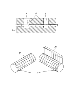
Referring firstly to Figure 1 there is illustrated a length of
pipeline 2 which is to be assessed and for which a prediction of
its condition is to be determined.
The pipeline can be of a number of kilometres in length and in
accordance with the invention at least one, and in the example
shown two, portions 4 of the pipeline are selected to be
measured. The portions which are selected may be selected to be
at a location which is identified as being most prone to
corrosion and therefore can be said to be most likely to be in
the worst condition along the length of the pipeline or may be at
locations where the maximum of the combined loading regimes
CA 02617779 2008-01-11
are being applied or may be randomly selected to be
representative of the deterioration of the length of pipeline.
With the portion to be measured having been determined, then
5 in accordance with the invention the condition of the soil 6 in
the vicinity of the pipeline portion 4 is required to be assessed.
In one embodiment this can be achieved by using the apparatus
as shown in Figure 2 in which electrodes 7,8, 10 are placed into
the soil above the portion of the pipe. Typically, one of the
10 electrodes is of copper, one of the electrodes is of the same
material as the pipe walls and the other electrode is of a
standard selected material. The electrodes are connected to a
processing device 12 and the data received is used to generate a
graphical representation 14 as shown in Figure 2 which is
representative of a Redox Factorised linear polarisation
resistance (LPR). This can be repeated for each of the measured
portions of the pipeline to determine whether the soil type is the
same at each portion location or not.
Other soil condition factors such as pH, ground type, moisture
content and heterogeneity may also be measured and taken into
account to give an indication of the soil type.
Most pipelines include a coating material on the external surface
of the same in order to try and protect the pipeline wall from
corrosion and the condition of this coating (if provided) is
assessed in accordance with the invention.
In accordance with the embodiment shown in Figure 3 this is
achieved by exposing the coating around the periphery of and
along the length of the portions 4 of the pipeline and
performing a visual check. The pipeline portion is represented
by a grid 16 and Figure 3a illustrates how this grid effectively is
mapped around the periphery of the coating of the pipeline
CA 02617779 2008-01-11
11
portion 4. Each cell 17 of the grid 16 is provided with a
coordinate 18 relating to the position round the circumference
of the pipeline and a coordinate 20 relating to the position along
the length of the pipeline. For example the cell 17 shown by the
reference arrows has the co-ordinates B800-900 on the grid 16.
The size of the grid can be selected to suit the pipeline in
question as can the size of area of the pipeline represented by
each of the cells. In one embodiment the width of the portion is
equivalent to the length of pipeline which can be measured by
monitoring apparatus without having to move the apparatus as a
whole along the pipeline portion.
For each cell 17 a value is allocated to the percentage of the
coating failure at that cell location. This value may in one
embodiment be with respect to the range of no coating to full
coating or alternatively may be with respect to an "average"
coating value. The values are then assessed and the areas with
the coating condition below a certain level can be identified in
this case by darker shading of the cells.
In addition, or alternatively to the above, a PCM signal may be
transmitted along the pipeline portion and detection means are
mounted externally of the pipeline to identify the same.
Typically the provision of the coating will act to mask or damp
the signal to a reduced strength when detected externally of the
pipeline. However if the coating is removed or thinner at any
location on the portion the signal will be detected as having a
greater strength thereby indicating the poor condition of the
coating at that location. Thus in accordance with this
embodiment the grid cells can again be filled with a reading
indicative of the condition of the coating at that cell but the
reading can be obtained from a position above ground via the
signal detection means thereby avoiding the need for the
pipeline portion to be available for a visual inspection.
CA 02617779 2008-01-11
12
In accordance with the invention the condition of the pipeline=
wall is assessed with particular reference to the pitting of the
wall. The assessment may be made with regard to the occurrence
of pitting regardless of whether the same depend from the
external or internal surface of the pipeline wall, or, alternatively
the location of the pitting with respect to the internal or
external surfaces can also be identified. In either case the
assessment is performed along the length of the portion and also
around the circumference of the portion of the pipeline portion.
The data indicative of the pitting is logged and mapped onto a
grid 20 with a series of cells 21 with coordinates so that the
location of the pitting is mapped to a specific location on the
pipeline portion. An example of the grid 22 is provided in
Figure 4 with each of the cells 21 having a corrosion value
allocated thereto. Once more the grid is mapped to the pipeline
portion 4 in a similar manner and with the same co-ordinates as
indicated in Figure 3a.
In whichever embodiment it is desired that the circumference of
the pipeline portion needs to be inspected. The number of
portions which are inspected along the length of the pipeline is
typically influenced by the need to identify and measure at least
a minimum number of statistically valid number of pitting
occurrences. For each cell where there is pitting only one pitting
occurrence in that cell counts as a defect.
When the pipeline material is metallic, the monitoring apparatus
used comprises means for emitting a magnetic flux or field and
sensing means, such as Hall Effect sensors for determining the
strength of the same at that location. The strength of the
detected magnetic flux or field is used to determine the presence
of pitting in the pipeline wall. In addition, one or more
proximity sensors are provided to allow the determination of
CA 02617779 2014-11-24
13
whether the pitting is present in the internal or external surface
of the pipeline wall. The apparatus is typically located on a
frame and one example of the same is provided in Figures 5a
and b. As shown in Figure 5a the detecting head 24 is capable of
moving in the direction of arrow 25 along the length of the
= frame 26 and the frame itself is capable of being moved around
the circumference of the pipeline wall 4 so that it will be
.
appreciated that the entire portion of the pipeline can be
measured. Typically the frame 26 is of a length to allow the
length of the pipeline portion to be measured without moving
the frame. As shown in Figure 5b, the detecting head includes a
sensor ring 30 which includes Hall effect sensors 32 which are
provided to detect magnetic flux leakage from the magnetic field
which is generated into the pipeline wall by the apparatus
electromagnets 120, 122. Proximity sensors 33 are also fitted
which allow the location of the defect either depending inwardly
from the outside wall of the pipeline or outwardly from the
inside wall of the pipeline. When the proximity sensors are
passed along a pipeline showing no or insignificant corrosion a
constant output signal is generated to be received from the
proximity sensors. However if a change in the condition of the
pipeline on or near to the external surface of the pipeline is
detected the reading from the proximity sensor will change
thereby indicating that the pitting detected by the Hall effect
sensors is at the external face of the pipeline wall rather than
the internal face.
In addition to detecting the presence of pitting, the depth of at
least the deepest pit in each cell is determined and mapped onto
a grid as shown in Figure 6. Thus, the frequency and spread of
the pitting is identified and also those areas where the pitting is
deepest, and hence the pipe wall thinnest, are identified.
,
CA 02617779 2008-01-11
=
14
In certain cases the material from which the pipeline wall is
formed prevents the uses of the magnetic field detection means.
In this case alternative apparatus in the form of a GPR device
can be used. The GPR device can be used in a similar manner to
that described above with the detection head being moved along
and around the portion so as to allow indicative readings to be
obtained.
With this measurement data available, the same can then be
graphically represented and processed such that, for example,
data relating to the current deepest pitting and number of
critical defects can be used to provide predicted values for the
future defects and future critical defect patterns.
These predictions can be made by using statistical analysis,
typically utilising suitable algorithms into which the measured
data can be input as appropriate. In addition to the measured
data other reference data and/or data from previous pipeline
measurements which are applicable to the current pipeline being
measured may be selectively obtained from a reference database
and used as required in the algorithms in order to provide an
accurate and reliable prediction for the whole of the pipeline
length to which the assessment is being applied rather than just
the portions which have been measured.
Other predictions which may be provided include predicted
internal and external pipeline wall defect patterns over the
defined length of pipeline as the likely ongoing corrosion rate
can be calculated with reference to the measured data and
known reference data. The predicted year of structural failure
may also be provided with reference to the measured wall
thickness and calculated critical wall defects and other reference
data such as the maximum loading regime on the pipeline.
CA 02617779 2008-01-11
Predictions of the effect of reducing or increasing the combined
loading regimes on the year of failure can also be made.
It will therefore be appreciated that the current invention
5 provides apparatus and a method which allows the scanning of
the condition of at least one portion of pipeline to be performed
in an efficient and reliable manner, and as a result the measured
data can be used to provide an accurate indication of the
condition of a length of the pipeline in which the said at least
10 one portion is located.