Note: Descriptions are shown in the official language in which they were submitted.
CA 02617801 2008-02-04
WO 2007/021310 PCT/US2006/006326
Monopole Field Electric Motor Generator
Background
Related Applications
[1] This application claims international priority from a prior filed U.S.
Utility Patent
Application having serial number 11200920 filed on August 9, 2005.
Field of the Present Disclosure
[2] This disclosure relates generally to electric motors and electric
generators and
more particularly to such rotating electromagnetic machines having monopole
fields.
Description of Related Art
[3] The following art defines the present state of the field of the apparatus
described
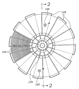
and claimed herein:
[4] Tu et al, US 2004/0135452, discloses a flat rotary electric generator that
includes
at least one toroidal coil structure for cutting magnetic lines to induce a
current and at
least one disc-shaped magnetic pole structure oriented parallel to the helical
coil
structure. If multiple toroidal coil structures and disc-shaped magnetic coil
structures
are included, the toroidal coil structures and disc-shaped magnetic coil
structures are
arranged in alternating manner. The toroidal coil structure and disc-shaped
magnetic
pole structure are not provided with a permeable material. When either the
toroidal
coil structures or the at least one disc-shaped magnetic pole structure is
rotated by an
external force, the toroidal coil structure cuts the magnetic lines passing
therethrough
1
CA 02617801 2008-02-04
WO 2007/021310 PCT/US2006/006326
to generate an induced current. Neal, US 2002/0135263, discloses a plurality
of
stator arc segments that form a toroidal core for a stator assembly used to
inalce a
motor. In a preferred embodiment, a plurality of magnetic fields is created
when
electrical current is conducted through wire wound around poles on the
toroidal core.
A monolithic body of phase change material substantially encapsulates the
conductors and holds the stator arc segments in contact with each other in the
toroidal
core. Hard disc drives using the motor, and methods of constructing the motor
and
hard disc drives are also disclosed. Rose, US 6803691, discloses an electrical
machine that comprises a magnetically permeable ring-shaped core centered on
an
axis of rotation and having two axially-opposite sides. Coils are wound
toroidally
about the core and disposed sequentially along the circumferential direction.
Each
coil includes two side legs extending radially alongside respectively sides of
the core.
Coil-free spaces exist between adjacent side legs. A bracket has first and
second side
flanges that are connected by a bridging structure and respectively abut the
first and
second sides of the coil. Mohler, US 6507257, discloses a bi-directional
latching
actuator that is comprised of an output shaft with one or more rotors fixedly
mounted
thereon. The shaft and rotor are mounted for rotation in a magnetically
conductive
housing having a cylindrical coil mounted therein and is closed by conductive
end
caps. The end caps have stator pole pieces mounted thereon. In one embodiment,
the
rotor has at least two oppositely magnetized perinanent magnets which are
asyinmetrically mounted, i.e., they are adjacent at one side and separated by
a non-
magnetic void on the other side. The stator pole piece has asyminetric flux
conductivity and in one embodiment is axially thiclcer than the remaining
portion of
the pole piece. An abutment prevents the rotor from swinging to the neutral
position
(where the rotor magnets are axially aligned with the higher conductivity
portion of
the pole piece). Thus, the rotor is magnetically latched in one of two
positions being
drawn towards the neutral position. Energization of the coil with an opposite
polarity
current causes the rotor to rotate towards its opposite latching position
whereupon it
is magnetically latched in that position. Mohler, US 5337030, discloses a
permanent
magnet brushless torque actuator that is comprised of an electromagnetic core
capable of generating an elongated toroidally shaped magnet flux field when
energized. Outside the generally cylindrical coil is an outer housing with
upper and
2
CA 02617801 2008-02-04
WO 2007/021310 PCT/US2006/006326
lower end plates at each end. Mounted to the end plates and extending towards
each
other are stator pole pieces separated from its opposing pole piece by an air
gap. A
permanent magnet rotor is disposed in the air gap and mounted on a shaft which
in
turn is rotatably mounted in each of the end plates. The permanent magnet
rotor
comprises at least two permanent magnets, each covering an arcuate portion of
the
rotor and having opposite polarities. Energization of the coil with current
in. one
direction magnetizes the pole pieces such that each of the two pole pieces
attracts one
of the magnets of the rotor and repels the other magnet of the rotor resulting
in a
torque generated by the output shaft. Reversal of the current flow results in
a reversal
of the torque and rotation of the rotor in the opposite direction. Preferred
embodiments are disclosed having multiple cells, i.e. a plurality of stator
rotor stator
combinations and/or cells in which there are a plurality of pole pieces at
each stator
pole plane. Kloosterhouse et al, US 5191255, discloses an electromagnetic
motor
that includes a rotor having a plurality of magnets mounted along a perimeter
of the
rotor. Preferably, adjacent magnets have opposite poles facing outward. One or
more
electromagnets are disposed adjacent to the perimeter of the rotor so that as
the rotor
rotates, the magnets mounted on the rotor are carried near the poles of the
electromagnets. Current is supplied to the electromagnets by a drive circuit
in a
predetermined phase relationship with the rotation of the rotor such that, for
substantially all angular positions of the rotor, magnetic attraction and
repulsion
between the poles of the electromagnets and the magnets mounted on the rotor
urge
the rotor to rotate in a desired direction. Reflective material is mounted on
the rotor
in predetermined angular positions. The drive circuit includes a
photosensitive device
which produces a signal whose value varies according to whether the device is
receiving light reflected from the reflective material. The signal is
amplified to
produce drive current for the electromagnets. Westley, 4623809, discloses a
stepper
motor housing a pole structure in which a pair of identical stator plates,
each having a
plurality of poles, are positioned back to back with the poles projecting in
opposite
directions, the stator plates being positioned between a pair of substantially
identical
stator cups, each stator cup having a plurality of poles projecting inwardly
from a
back wall with a peripheral side wall terininating in an outwardly extending
flange. A
major surface of each flange is in contact with a face on one of the stator
plates so as
3
CA 02617801 2008-02-04
WO 2007/021310 PCT/US2006/006326
to assure a low reluctance magnetic path. Fawzy, 4565938, discloses an
electromechanical device which can be used as a motor or as a generator. The
device
has a housing, including bearing means to support a rotatable shaft. Disc
magnet
means are provided, and poled to have alternating polarity and are mounted on
the
shaft to define a rotor. The device includes at least one first pole shoe in
contact with
the magnet means, having a portion extending radially therefrom to define a
virtual
pole chainber, of a first polarity. Also included is at least one second pole
shoe in
contact with the magnet and having a portion extending radially therefrom to
define a
virtual pole chamber of the other polarity. A toroid stator is mounted on the
housing
and has windings thereon. The stator is positioned annularly around the disc
magnets
such that the virtual pole chambers of the first and second pole shoes
surround
portions of said windings with circumferentially alternating fields of
alternating
polarity. Means are provided for electrical contact with the stator to draw
off current
when the device is operated as a generator, or provide current to operate the
device as
a motor. Fawzy, 4459501, discloses an electromechanical device which can be
used
as a motor or as a generator that has a housing, including bearing means to
support a
rotatable shaft. A pair of disc magnets are poled to have opposite polarity on
the two
faces of each. The magnets are mounted face to face together on the shaft to
define a
rotor. The device includes at least one first pole shoe in contact with one
face of each
magnet, and having a portion extending radially therefrom to define, in its
preferred
form, a pair of virtual pole chainbers, of the same polarity as said one face.
Also
included is at least one second pole shoe in contact with the other face of
each
magnet and having a portion extending radially therefrom to define in its
preferred
form a pair of virtual pole chambers of the same polarity as the other face. A
toroid
stator is mounted on the housing and has windings thereon. The stator is
positioned
annularly around the disc magnets such that the virtual pole chambers of the
first and
second pole shoes surround portions of said windings with circumferentially
alternating fields of alternating polarity. Means for electrical contact with
the stator
draw off current when the device is operated as a generator, or provide
current to
operate the device as a motor.
4
CA 02617801 2008-02-04
WO 2007/021310 PCT/US2006/006326
[5] Our prior art search with abstracts described above teaches rotating
electromagnet
machines; in both motor and generator forms. Thus, the prior art shows in
Neal, a
toroidal core witli radial are segments, in Fawzy, we see a N-N and S-S pole
face
adjacency, in Tu et al, a N-S and S-N pole adjacency with radial coil
windings, in
Rose, we find radially wound coils in sequence around a toroidal core and with
permanent magnet segments with N-N and S-S adjacency. However, the prior art
fails to teach a rotating electromagnetic machine that provides
electromagnetic fields
immersed in monopole permanent magnet fields of opposite polarities as is
shown in
the present apparatus.
[6] The present disclosure distinguishes over the prior art providing
heretofore
unknown advantages as described in the following summary.
Summary
[7] This disclosure teaches certain benefits in construction and use which
give rise to
the objectives described below.
[8] A rotating electromagnetic apparatus has a stator including a stator frame
supporting parallel spaced apart, disc-shaped perinanent magnet sets. Each of
the
magnet sets is formed as plural, spaced apart, co-planar magnet segments. The
segments are arranged with permanent magnet poles of opposite polarity in an
alternating sequence. A rotor provides a magnetically permeable rotating rotor
frame
mounted on an axle and supported by the stator fraine. The rotor frame
provides a
plurality of radially oriented, toroidally wound coils. Like poles of the
magnet sets
are set in opposing, face-to-face positions with the rotor between them. A
current
supplying commutator engages the rotor such that each of the coils provides
electromagnet poles positioned alternately for attraction and repulsion of the
electromagnet poles with respect to the permanent magnet poles thereby causing
rotor
rotation.
5
CA 02617801 2008-02-04
WO 2007/021310 PCT/US2006/006326
[9] A primary objective inherent in the above described apparatus and method
of use
is to provide advantages not taught by the prior art.
[10] Another objective is to provide an electromagnetic rotating machine with
superior
torque relative to conventional machines.
[11] A further objective is to provide such a machine useful as an electric
motor.
[12] A further objective is to provide such a machine useful as an electric
generator.
[13] A further objective is to provide such a machine that is able to be
operated as a
DC or as an AC device.
[14] A still further objective is to provide such a machine that is useful as
a power
converter.
[15] Other features and advantages of the described apparatus and method of
use will
become apparent fi=om the following more detailed description, talcen in
conjunction
with the accompanying drawings, which illustrate, by way of example, the
principles
of the presently described apparatus and method of its use.
Brief Description of the Drawings
[16] The accompanying drawings illustrate at least one of the best mode
embodiments
of the present apparatus and method of it use. In such drawings:
[17] Figure 1 is an elevational view of a rotor of the apparatus showing a
commutator
and brushes;
[18] Figure 2 is a vertical cross-sectional view thereof taken along line 2-2
in Fig. 1;
6
CA 02617801 2008-02-04
WO 2007/021310 PCT/US2006/006326
[19] Figure 3 is a perspective view thereof conceptually showing the stator as
two pair
of semicircular magnet sets, with the rotor positioned medially;
[20] Figure 4 is a perspective view thereof conceptually showing the stator as
rings of
four magnet sets, with the rotor positioned medially;
[21] Figure 5 is a perspective view thereof conceptually showing the stator as
rings of
eight magnet sets, with the rotor positioned medially;
lo [22] Figure 6 is a perspective view thereof conceptually showing the stator
as rings of
twelve magnet sets, with the rotor positioned medially;
[23] Figure 7 is a perspective view thereof showing construction details of
the rotor;
[24] Figure 8 is a cross-sectional view thereof showing the commutator and
brushes of
the apparatus;
[25] Figure 9 is a side elevational view thereof showing the commutator and
brushes;
[26] Figure 10 is an electrical schematic diagram thereof configured for DC
operation
with high torque and moderate speed;
[27] Figure 11 is an electrical schematic diagrain thereof configured for DC
operation
with high speed and high torque;
[28] Figure 12 is an electrical schematic diagram thereof configured for AC
operation;
[29] Figure 13 is an electrical schematic diagram thereof configured for DC
operation
with low current and high speed; and
[30] Figure 14 is an electrical schematic diagram thereof configured for AC
operation
with high voltage.
7
CA 02617801 2008-02-04
WO 2007/021310 PCT/US2006/006326
Detailed Description
[31] The above described drawing figures illustrate the described apparatus
and its
method of use in at least one of its preferred, best mode embodiments, which
is
further defined in detail in the following description. Those having ordinary
skill in
the art may be able to malce alterations and modifications to what is
described herein
without departing from its spirit and scope. Therefore, it must be understood
that
what is illustrated is set forth only for the purposes of example and that it
should not
be talcen as a limitation in the scope of the present apparatus and method of
use.
[32] A rotating electromagnetic apparatus comprises a stator including a
stator frame
152 supporting parallel spaced apart, disc-shaped permanent magnet sets,
wherein
each of the magnet sets comprises plural, spaced apart, co-planar magnet
segments
146. The segments 146 are arranged with pairs of opposing N-N and S-S
perinanent
magnet poles, as shown by the letters "S" for south pole and "N" for north
pole, of
opposite polarity in alternating circumferential sequence as is shown in Figs.
3-6
depicting four separate possible configurations of the magnet sets. A rotor
provides a
magnetically permeable rotating rotor frame 140 mounted on, and rotating with,
an
axle 144 which is supported by the stator frame 152 as shown in Fig. 2. Rotor
frame
140 includes central structural element 156 fixed to axle 144. The rotor
fraine 140
provides a plurality of radially oriented, toroidally wound coils 148 as shown
in Figs.
1, 2 and 10. Like poles of the magnet segments 146 are in opposing, face-to-
face
positions with the rotor positioned therebetween. A current supplying
cominutator
158 engages the rotor such that each of the coils 148 provide, on each side of
its
plane, an electromagnet active monopole 168 as shown in Fig. 1, which are
positioned for attraction or repulsion of the adjacent permanent magnet poles
in a
manner causing rotation of the rotor. The permanent magnets induce magnetic
monopole fields in the ferromagnetic core. Axle 144 rotates within a bearing
in
fraine 152 and the fraine 152 includes structural elements 150 for supporting
the
stator.
8
CA 02617801 2008-02-04
WO 2007/021310 PCT/US2006/006326
[33] The inagnet segments 146 may comprise two semicircular segments as shown
in
Fig. 3, four segments in quadrature, as shown in Fig. 4, eight segments, as
shown in
Fig. 5, twelve segments, as shown in Fig. 6, or may comprise any number of
such
segments 148. The segments 146 are mounted on discs 142 made of ferromagnetic
material. When more than two segments are used, the commutator is also
segmented
accordingly. In the following description, we shall discuss the configuration
shown
in Fig. 3, however, the basic principals of the present apparatus and theory
of
operation apply as well to Figs. 4-6, and apply as well to a linear embodiment
of the
present rotating toroidal machine as would be able to be enabled by one of
skill in the
art.
[34] The rotor frame 140 may be made up of layers of ferromagnetic sheet
material
164 as shown in Fig. 1, or it may be a monolithic sintered ferrite part as
shown in Fig.
7 which eliminates hysteresis. Electrical conductors in the form of insulated
wires
are wound into coils 148 within radial slots 130 formed in the rotor frame 140
(Fig.
7). These coils 148 are interconnected as shown in Fig. 10, i.e., all of the
coils 148
are wired so as to have an electrically common point 183 in Figs. 2 and 10 at
one end
of the coils 148. The other end of each of the coils 148 is connected to a
wiper 158
which slides on commutator 159 as best shown in Fig. 8.
[35] In Fig. 8 we see that the wipers 158 are preferably set at an angle to
the axis of
axel 144 to obtain improved contact surface area with commutators 159, which
are
spring loaded for continuous contact with the wipers 158. In Fig. 9 we see
that the
wipers 158 are set very close together, but it is noted that they do not touch
each
other.
[36] In operation, the apparatus is set into rotational motion, the rotor
rotating between
and in close adjacency on both of its sides to the stator. Referring now to
Fig. 10, it
is seen that, in the preferred embodiment of the current apparatus, a pair of
perinanent
magnet north poles N of semicircular segment 146 configuration are in close
proximity to one half of the coils 148 at each instant, while a pair of
pernianent
magnet south pole S semicircular segments 146 are in close proximity to the
other
9
CA 02617801 2008-02-04
WO 2007/021310 PCT/US2006/006326
half of the coils 148. The coils sandwiched between the N pole magnets are
polarized by current flow through the commutator 159 to produce magnetic field
alignments that result in rotational forces. To understand this, it is
important to
recognize that the ferromagnetic rotor body 140 that is instantaneously
positioned
between the N pole permanent magnet segments 146 is induced as a south pole S.
Each of the coils 148 mounted in the rotor body 140 that are also between the
N pole
permanent magnet segments 146 have a current sense producing a magnetic field
that
causes attraction to the rotor body 140 to product an electromotive fore in
the
direction of rotation, see the description in the incorporated Provisional
Patent
Application on page 20 and associated Fig. 9. Likewise, the saine effect with
opposite polarities occurs for those coils 148 that are between the S pole
magnet
segments 146.
[37] Generally, the present apparatus is a rotating electromagnetic machine
having a
stator which provides at least one permanent monopole magnetic field within
its
interior space. A ferromagnetic toroidal rotor body 140 has an outer
circumference
140', and inner circumference 140" as shown in Fig. 7. The body 140 also
includes
two opposing side walls 140"'. The rotor body 140 is immersed in the permanent
magnetic field and thereby has induced into it, a monopole magnetic field of
opposite
polarity. At least one, and preferably a plurality of current carrying
electrical coils
148 are wound around the rotor body within radially directed slots 130 on both
of the
side walls 140"' of the rotor body 140. The electrical coils 148 produce a
electromagnetic field directed along a sense of rotation of the rotor body
within the
stator thereby producing an electromotive force.
[38] Assuming electron current flow from the positive terminal (+) to the
negative
terminal (-), the flow is therefore through all of the coils 148 associated
with the
perinanent S pole first, and then through all of the coils 148 associated with
the
perinanent N pole. As coils 148 transfer across the gap between the positive
and
negative commutator (brushes) 159 current flow reverses and then so does the
force
exerted on the coils 148, and since the permanent magnetic field also reverses
its
polarity at the same time, the rotor develops a constant rotational force. It
is the fact
CA 02617801 2008-02-04
WO 2007/021310 PCT/US2006/006326
that the coils 148 find themselves immersed within a monopole, i.e., either a
N pole
field or a S pole field, that they develop an electromotive force
significantly larger
then alternative electromagnetic rotating machines.
[39] The enablements described in detail above are considered novel over the
prior art
of record and are considered critical to the operation of at least one aspect
of the
apparatus and its method of use and to the achievement of the above described
objectives. The words used in this specification to describe the instant
embodiments
are to be understood not only in the sense of their commonly defined meanings,
but
to include by special definition in this specification: structure, material or
acts beyond
the scope of the commonly defined meanings. Thus if an element can be
understood
in the context of this specification as including more than one meaning, then
its use
must be understood as being generic to all possible meanings supported by the
specification and by the word or words describing the element.
[40] The definitions of the words or drawing elements described herein are
meant to
include not only the combination of elements which are literally set forth,
but all
equivalent structure, material or acts for performing substantially the saine
function
in substantially the same way to obtain substantially the same result. In this
sense it is
therefore contemplated that an equivalent substitution of two or more elements
may
be made for any one of the elements described and its various embodiments or
that a
single element may be substituted for two or more elements in a claim.
[41] Changes from the claimed subject matter as viewed by a person with
ordinary
skill in the art, now lcnown or later devised, are expressly contemplated as
being
equivalents within the scope intended and its various embodiments. Therefore,
obvious substitutions now or later lcnown to one with ordinary skill in the
art are
defined to be within the scope of the defined elements. This disclosure is
thus meant
to be understood to include what is specifically illustrated and described
above, what
is conceptually equivalent, what can be obviously substituted, and also what
incorporates the essential ideas.
11
CA 02617801 2008-02-04
WO 2007/021310 PCT/US2006/006326
[42] The scope of this description is to be interpreted only in conjunction
with the
appended claims and it is made clear, here, that each nained inventor believes
that the
claimed subject matter is what is intended to be patented.
12