Note: Descriptions are shown in the official language in which they were submitted.
CA 02617819 2008-01-10
PHOTOVOLTAIC ROOFING PANEL
FIELD OF THE INVENTION
[0001] The disclosure relates generally to photovoltaic panels, and more =
= particularly to photovoltaic panels configured for disposal on a roof.
BACKGROUND
[0002] Photovoltaic strips employ solar power technology that uses solar
photovoltaic arrays to convert energy from the sun into electricity.
Photovoltaic arrays
are a linked collection of photovoltaic modules. Each photovoltaic module is
made of
multiple interconnected solar cells that typically include silicone. The cells
convert solar
energy into direct current electricity, and work via photovoltaic effect. This
effect
converts sunlight into electricity.
[0003] An effective means of assocaiting photovoltaics with roof structures
(particularly existing roof structures) would be desirable in that it could
provide an
energy efficient way to generate electrciity.
SUMMARY OF THE INVENTION
[0004] Disclosed is a photovoltaic roofing panel including at least one
photovoltaic collector strip and a substrate configured to be disposed on a
roof deck, the
at least one photovoltaic collector strip being fixedly associated with the
substrate.
[0005] Also disclosed is a photovoltaic roofing system including a roof deck
at
least one photovoltaic panel disposed with the roof deck, the at least one
panel
comprising at least one photovoltaic collector strip and a substrate
configured to be
disposed with the roof deck, the at least one photovoltaic collector strip
being fixedly
=
associated with the substrate.
1
CA 02617819 2014-09-10
,
[0006] Further disclosed is a photovoltaic panel arrangement including a
plurality of photovoltaic panels, each of the plurality of panels including at
least one
photovoltaic collector strip and a substrate configured to be disposed on a
roof deck,
the at least one photovoltaic collector strip being fixedly associated with
the
substrate, and a means of associating the plurality of photovoltaic panels.
[0007] Still further disclosed is a method for providing photovoltaic power,
the method including fixedly associating at-least one photovoltaic strip with
a
substrate configured to be disposed on a roof of a structure, disposing the
substrate
on the roof, and electrically associating the at least one photovoltaic strip
with the
structure.
[0007a] In accordance with one aspect of the present invention, there is
provided a photovoltaic roofing panel comprising: at least one photovoltaic
collector
strip; and a semi-flexible board configured to be disposed on a roof deck,
said at
least one photovoltaic collector strip being fixedly associated with said semi-
flexible
board, wherein said semi-flexible board defines channels configured for
disposal of
conductive material and positioned relatively below said strip, said
conductive
material being configured to carry electricity generated by said at least one
photovoltaic collector strip.
[0007b] In accordance with another aspect of the present invention, there is
provided a photovoltaic roofing system comprising: a roof deck; at least one
photovoltaic panel disposed with said roof deck, said at least one panel
comprising
at least one photovoltaic collector strip and a semi-flexible board configured
to be
disposed with said roof deck, said at least one photovoltaic collector strip
being
fixedly associated with said substrate, wherein said semi-flexible board
defines
channels configured for disposal of conductive material and positioned
relatively
2
CA 02617819 2014-09-10
,
below said strip, said conductive material being configured to carry
electricity generated by said at least one photovoltaic collector strip.
[0007c] In accordance with another aspect of the present invention there is
provided a photovoltaic panel arrangement comprising: a plurality of
photovoltaic
panels, each of said plurality of panels comprising at least one photovoltaic
collector
strip and a semi-flexible board configured to be disposed on a roof deck, said
at least
one photovoltaic collector strip being fixedly associated with said substrate,
wherein
said semi-flexible board defines channels configured for disposal of
conductive
material and positioned relatively below said strip, said conductive material
being
configured to carry electricity generated by said at least one photovoltaic
collector
strip; and a means of associating said plurality of photovoltaic panels.
[0007d] In accordance with another aspect of the present invention, there is
provided a method for providing photovoltaic power, the method comprising:
fixedly associating at least one photovoltaic strip with a semi-flexible board
configured to be disposed on a roof of a structure, wherein said semi-flexible
board
defines channels configured for disposal of conductive material and positioned
relatively below said strip, said conductive material being configured to
carry
electricity generated by said at least one photovoltaic collector strip;
disposing said
semi-flexible board on said roof; and electrically associating said at least
one
photovoltaic strip with said structure.
BRIEF DESCRIPTION OF THE FIGURES
[0008] Referring to the drawings wherein like elements are numbered alike
in the several Figures:
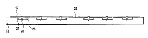
[0009] Figure 1 is a top perspective of a photovoltaic roofing panel; [0010]
Figure 2 is a side view of the photovoltaic roofing panel;
2a
CA 02617819 2014-09-10
[0011 ] Figure 3 is a side view of the photovoltaic roofing panel including
mechanical fasteners;
[0012] Figure 4 is a side view of the photovoltaic roofing panel including
Velcro; [0013] Figure 5 is a side view of the photovoltaic roofing panel
including
conductive material;
[0014] Figure 6 is a side view of the photovoltaic roofing panel including
conductive material disposed within the a substrate of the panel;
[0015] Figure 7 is a side view of the photovoltaic roofing panel electrically
connected form a relative underside of a photovoltaic strip of the panel;
2b
CA 02617819 2008-01-10
[0016] Figure 8 is a side view of the photovoltaic roofing panel electrically
connected form a relative underside of a photovoltaic strip of the panel,
through the
substrate of the panel;
[0017] Figure 9 is a side view of the photovoltaic roofing panel electrically
connected form a relative top of a photovoltaic strip of the panel;
[0018] Figure 10 is a top perspective of a photovoltaic roofing panel
including a
solar radiation transmutable film;
= [0019] Figure 11 is a top view of a photovoltaic roofing system;
= [0020] Figure 12 is a side view of the photovoltaic roofing system
including an
insulation layer;
[0021] Figure 13 is a side view of the photovoltaic roofing system including
an
= insulation layer and spacers;
[0022] Figure 14 is a side view of the photovoltaic roofing system including
an
insulation layer that creates an angles disposal of the panels of the system;
[0023] Figure 15 is a top view of the photovoltaic roofing system including
panels that are associated via flexible sheets;
[0024] Figure 16 is a side view of two panels of Figure 15, the panels .being
away
from disposal on a rootand
[0025] Figure 17 is a block diagram illustrating a method for providing
= photovoltaic power.
3
CA 02617819 2008-01-10
DETAILED DESCRIPTION
[0026] Referring to Figures 1 and 2, a photovoltaic roofing panel 10 is
illustrated.
The roofing panel 10 includes at least one photovoltaic collector strip 12 and
a substrate
14 configured to be disposed on a roof deck 16 of a structure 17 (i.e., a
previously
existing roof deck of a building building). The photovoltaic strip 12 is
fixedly associated
with the substrate 14. The photovoltaic strip 12 is affixed to the substrate
14 via any
means desirable, such as adhesive.
[0027] Photovoltaic strips such as the strip 14 employ solar power technology
that uses solar photovoltaic arrays (within the weather-resistant strips 14)
to convert
energy from the sun into electricity. Photovoltaic arrays are a linked
collection of
photovoltaic modules. Each photovoltaic module is made of multiple
interconnected
solar cells that typically include silicone. The cells convert solar energy
into direct
current electricity, and work via photovoltaic effect.
[0028] Photovoltaic effect employs a photogeneration of charge carriers
(electrons) in a light-absorbing material, and separation of the charge
carriers to a
conductive contact that will transmit the electricity. This effect converts
sunlight into
electricity. The elctricity generated can be significant when photovoltaic
solar cells are
connected together in photovoltaic modules, arrays, and ultimately strips 14.
[0029] Referring back to the exemplary embodiment of Figures 1 and 2, the
photvoltaic strips 12 are flexible, and fixedly associated with with the
substrate 14 in
pairs (though certain applications of the photovoltaic roofing panel 10 may
require more
or less strips 12). In an exemplary embodiment, the substrate 14 is a semi-
flexible plastic
board (such as polyethylene) of a weight substantial enough to allow the
substrate 14 to
be loose laid on the roof 16. It should be appreciated however, that other
substrate
materials, such as air permeable cloth, may also be used as the substrate 14.
Use of air
permeable cloth would allow for air permeable spaces between the strips 12.
4
CA 02617819 2008-01-10
[0030] It should also be appreciated that the roofing panel 10 is associable
with
the roof 16 via applications other than loose laying. Referring to Figure 3,
the panel 10 is
associated with the roof 16 via mechanical fasteners 18 (such as threaded
instruments)
that run through the substrate 14 and into the roof 16. Referring to Figure 4,
the panel 10
is associated with the roof 16 via cdmpatible Velcro strips 21 affixed to a
relative lower
surface 20 of the substrate 14, and a relative upper surface 22 of the roof
16.
[0031] Referring to the embodiment of Figures 5 and 6, the substrate 14
defines
band channels 24. These channels 24 may be open at a relative top surface 25
of the
substrate 14, as shown in Figure 5, or may be enclosed entirely within the
substrate 14, as _ =
shown in Figure 6. These channels 24 are configured to hold conductive metal
bands 26.
The conductive metal bands 26 are electrically associated with the
photovoltaic strips 12
via conductive connectors 28 (such as metallic threaded instruments) that run
from the
strips 12, through the substrate 14 (if the channels 24 are enclosed within
the substrate 14
as in Figure 6), and into electrical association with the bands 26. The bands
26 conduct
electricity generated by the strips 12 to a power receiver 30 on the roof 16,
wherein the
power receiver 30 supplies electricity to a building to which the roof 16 is
attached. The
bands 26 of adjacent panels 10 may be electrically connected (or of unitary
construction
with each other) to facilitate conduction of the electricity to the power
receiver 30 from
the strips 12 that are disposed remotely of the power receiver 30 on the roof
16.
Electrical connections 32 from the bands 26 to the power receiver 30 may
extend directly
from the band 26 to the receiver 30 (as shown in Figure 6), or from the band
26, through
the substrate 12, and into the receiver 30.
[0032] As shown in the embodiment of Figures 7-9, the photovoltaic strip 12
can
also be directly connected to the power. receiver 30 (i.e. without using the
conductive
bands 26 discussed above). The electrical connection 32 may extend from a top,
bottom,
or edge of the strip 12, and may or may not extend through the substrate 14.
If the
electrical connection 32 does extend through the substrate 14, it may do so
via a
connection channel 34 (as shown in Figure 8).
=
=
CA 02617819 2008-01-10
[0033] It should be appreciated that plastic board substrate 14 discussed
above
may comprise a self-sealing material that allows a threaded instilment to self-
seal with
the substrate 14 upon installment. Referring to Figure 10, it should also be
appreciated
that the panel 10 may include a solar radiation transmutable film 35 disposed
upon the
photovoltaic strip 14. =
[0034] Referring now to Figure 11, a photovoltaic roofing system 100 is
illustrated. The system 10 includes multiple photovoltaic roofing panels 10,
which are
contemplated to be inclusive of the elements discussed above (like elements
will be
numbered as above). As shown in Figure 11, the multiple panels 10 are arranged
in
longitudinal rows 102. The panels 10 of each row 102 are connected via
electric panel
= connections 105 that extend between and electrically associate the
photovoltaic strips 12
of longitudinally adjacent panels 10. Each of these connections 105 may be
detachable
from each strip 12 the individual connections 105 associate. The strips 12 of
one of the
panels 10 electrically associates the row 102 it resides in with one or more
power
receivers 30 via the electrical connections 32. It should be appreciated that
though Figure
11 illustrates electric associating between the power receivers 30 and the
panels 10 on the
relative left end of the rows 102, any panel may electrically associate the
row 102 it
resides in (or the panel 10 individually) with any power receiver 30 disposed
anywhere
on the roof 16. It should be further appreciated that the conductive bands 26
discussed
above may also be used to connect the panels 10 of the rows 102 in the system
100.
[0035] Referring to Figure 12-14, an insulation layer 104 is disposed between
the
roof 16 and the substrates 14. As shown in Figure 12, the insulation layer 103
may
define circulation channels 107 in an insulation surface 106 adjacent to the
photovoltaic
panels 10. These channels facilitate air circulation beneath the panels 10.
Alternatively
to the channels 104, and as shown in Figure 13, spacers 108 may be disposed
between the
insulation layer 103 and the panels 10. These spacers 108 also facilitate air
circulation
beneath the panels 10.*
6
CA 02617819 2008-01-10
[0036] Referring specifically to Figure 14, the insulation layer 103 is
disposed on
the roof deck 16 to include at least one high point 110 that tapers down to at
least one low
point 112. This tapering creates an angled disposal of the insulation layer
103, which
further creates an angled disposal of the panels 10 disposed upon the
insulation layer 103.
This angled disposal of the panels 10 may allow for enhanced solar exposure
and
collection.
[0037] Referring to Figures 15 and 16, in addition to being electrically
connected
(or connectable), the panels 10 in the rows 102 may also be connected via
flexible sheets
114. These sheets 114 may be folded back upon themselves as shown in Figure
16, so as
to allow convenient transportation of the rows 102 prior to installation upon
the roof 16.
The sheets 114 may house the electric panel connections 105, providing the
connections
105 with some protection from weather.
[0038] Figure 17 illustrates a method 200 for providing photovoltaic power.
The
method includes fixedly associating at least one photovoltaic strip 12 with a
substrate 14.
configured to be disposed on a roof 16 of a structure 17, as shown in
operational block
202. The method 200 also includes disposing the substrate 14 on the roof 16,
and
electrically associating the at least one photovoltaic strip 12 with the
structure 17, as
shown in operational block 204.
[0039] While the invention has been described with reference to an exemplary
embodiment, it should be understood by those skilled in the art that various
changes may
be made and equivalents may be substituted for elements thereof without
departing from
the scope of the invention. In addition, many modifications may be made to
adapt a
particular situation or substance to the teachings of the invention without
departing from
the scope thereof. Therefore, it is important that the invention not be
limited to the
= particular embodiment disclosed as the best mode contemplated for
carrying out this
invention, but that the invention will include all embodiments falling within
the scope of
the apportioned claims. Moreover, unless specifically stated any use of the
terms first,
7
CA 02617819 2008-01-10
second, etc. do not denote any order or importance, but rather the terms
first, second, etc.
are used to distinguish one element from another.
8