Note: Descriptions are shown in the official language in which they were submitted.
CA 02618105 2008-02-07
WO 2007/024485 PCT/US2006/031053
DESCRIPTION
MICROFLUIDIC SYSTEMS, DEVICES AND METHODS FOR REDUCING
DIFFUSION AND COMPLIANCE EFFECTS AT A FLUID MIXING REGION
CROSS-REFERENCE TO RELATED APPLICATIONS
This application claims the benefit of U.S. Patent Application Serial No.
60/707,220, filed August 11, 2005, the disclosure of which is incorporated
herein by reference in its entirety. The disclosures of the following U.S.
Provisional Applications, commonly owned and simultaneously filed August 11,
2005, are all incorporated by reference in their entirety: U.S. Provisional
Application entitled MICROFLUIDIC APPARATUS AND METHOD FOR
SAMPLE PREPARATION AND ANALYSIS, U.S. Provisional Application No.
60/707,373 (Attorney Docket No. 447/99/2/1); U.S. Provisional Application
entitled APPARATUS AND METHOD FOR HANDLING FLUIDS AT NANO-
SCALE RATES, U.S. Provisional Application No. 60/707,421 (Attorney Docket
No. 447/99/2/2); U.S. Provisional Application entitled MICROFLUIDIC BASED
APPARATUS AND METHOD FOR THERMAL REGULATION AND NOISE
REDUCTION, U.S. Provisional Application No. 60/707,330 (Attorney Docket
No. 447/99/2/3); U.S. Provisional Application entitled MICROFLUIDIC
METHODS AND APPARATUSES FOR FLUID MIXING AND VALVING, U.S.
Provisional Application No. 60/707,329 (Attorney Docket No. 447/99/2/4); U.S.
Provisional Application entitled METHODS AND APPARATUSES FOR
GENERATING A SEAL BETWEEN A CONDUIT AND A RESERVOIR WELL,
U.S. Provisional Application No. 60/707,286 (Attorney Docket No. 447/99/2/5);
U.S. Provisional Application entitled MICROFLUIDIC SYSTEMS, DEVICES
AND METHODS FOR REDUCING NOISE GENERATED BY MECHANICAL
INSTABILITIES, U.S. Provisional Application No. 60/707,245 (Attorney Docket
No. 447/99/3/2); U.S. Provisional Application entitled MICROFLUIDIC
SYSTEMS, DEVICES AND METHODS FOR REDUCING BACKGROUND
AUTOFLUORESCENCE AND THE EFFECTS THEREOF, U.S. Provisional
Application No. 60/707,386 (Attorney Docket No. 447/99/3/3); U.S. Provisional
Application entitled MICROFLUIDIC CHIP APPARATUSES, SYSTEMS, AND
METHODS HAVING FLUIDIC AND FIBER OPTIC INTERCONNECTIONS,
-1-
CA 02618105 2008-02-07
WO 2007/024485 PCT/US2006/031053
U.S. Provisional Application No. 60/707,246 (Attorney Docket No. 447/99/4/2);
U.S. Provisional Application entitled METHODS FOR CHARACTERIZING
BIOLOGICAL MOLECULE MODULATORS, U.S. Provisional Application No.
60/707,328 (Attorney Docket No. 447/99/5/1); U.S. Provisional Application
entitled METHODS FOR MEASURING BIOCHEMICAL REACTIONS, U.S.
Provisional Application No. 60/707,370 (Attorney Docket No. 447/99/5/2); U.S.
Provisional Application entitled METHODS AND APPARATUSES FOR
REDUCING EFFECTS OF MOLECULE ADSORPTION WITHIN
MICROFLUIDIC CHANNELS, U.S. Provisional Application No. 60/707,366
(Attorney Docket No. 447/99/8); U.S. Provisional Application entitled PLASTIC
SURFACES AND APPARATUSES FOR REDUCED ADSORPTION OF
SOLUTES AND METHODS OF PREPARING THE SAME, U.S. Provisional
Application No. 60/707,288 (Attorney Docket No. 447/99/9); U.S. Provisional
Application entitled BIOCHEMICAL ASSAY METHODS, U.S. Provisional
Application No. 60/707,374 (Attorney Docket No. 447/99/10); U.S. Provisional
Application entitled FLOW REACTOR METHOD AND APPARATUS, U.S.
Provisional Application No. 60/707,233 (Attorney Docket No. 447/99/11); and
U.S. Provisional Application entitled MICROFLUIDIC SYSTEM AND
METHODS, U.S. Provisional Application No. 60/707,384 (Attorney Docket No.
447/99/12).
TECHNICAL FIELD
The subject matter disclosed herein relates to microfluidic systems,
devices and methods for fabricating and using the same. More particularly, the
subject matter disclosed herein relates to microfluidic systems, devices and
methods for reducing diffusion effects at a fluid mixing region.
BACKGROUND ART
Microfluidic systems have been deveioped for miniaturizing and
automating the acquisition of chemical and biochemical information, in both
preparative and analytical capacities. These systems have resulted in
decreased cost and improved data quality. Microfluidic systems typically
include one or more microfluidic chips for conducting and mixing small amounts
-2-
CA 02618105 2008-02-07
WO 2007/024485 PCT/US2006/031053
of fluids, reagents, or other flowable composition or chemical for reaction
and
observation. Microfluidic chips can be fabricated using photolithography, wet
chemical etching, laser micromachining, and other techniques used for the
fabrication of microelectromechanical systems. Generally, microfluidic systems
can also include one or more computers, detection equipment, and pumps for
controlling the fluid flow into and out of the chip for mixing two or more
reagents
or other fluids together at specific concentrations and observing any
resulting
reaction.
Typically, microfluidic chips include a central body structure in which
various microfluidic elements are formed for conducting and mixing fluids. The
body structure of the microfluidic chip can inciude an interior portion which
defines microscale channels and/or chambers. Typically, two or more different
fluids are advanced to a mixing junction or region at a controlled rate from
their
respective sources for mixing at desired concentrations. The mixed fluids can
then be advariced to at least one main channel, a detection or analysis
channel,
whereupon the mixed fluids can be subjected to a particular analysis by
detection equipment and analysis equipment, such as a computer.
A primary challenge in the design of microfluidic systems is the
elimination or reduction of noise in the concentration of fiuids mixed at the
mixing junction. Noise in the fluid mix concentration is any deviation of the
actual fluid mix concentration from the desired fluid mix concentration. This,
in
turn, affects the quality of data measured by the detection equipment
downstream. The quality of data is dependent upon the observed signal-to-
noise ratio (SNR). To obtain good analysis data, it is important that the
different
fluids are mixed in expected concentrations in accordance with an experiment
design. Noise can be introduced in the concentration of fluid mixed, for
example, by temperature-dependent reagents that cause changes in chemical
signals that produce apparent changes in the concentration of fluids as
measured by a detector of that chemical signal. Noise can also be introduced
by unwanted diffusion of components of one fluid into another fluid at points
of
convergence of fluids, especially if one of the fluids is held stationary
(zero flow)
for any time. Additionally, noise can be introduced by thermal expansion or
unexpected pressure-driven expansion of components of the microfluidic chip
-3-
CA 02618105 2008-02-07
WO 2007/024485 PCT/US2006/031053
which can cause changes in volume that alter volumetric flow rates in the
chip.
Noise can also be introduced by thermal expansion or unexpected pressure-
driven expansion of any components in the pumps that affect movement of, for
example, the plunger relative to the barrel of a syringe pump. Noise can also
be introduced by thermal expansion or unexpected pressure-driven expansion
of any components in contact with the fluid in the system, such as any tubing
that connects different components, such as the pumps and the microfluidic
chip. Noise can arise from mechanical instabilities in the microfluidic device
or
system. The most common source of "mechanical" noise is from the pumps.
Any variations in motor speed and any "chatter" in moving parts of the pump,
such as the translation stage or piston of a microsyringe, can produce
oscillations in the flow of one fluid independent of the intended flows for
mixing
the fluids, thus resulting in noise. lf these occur upstream from the mixing
junction, noise can be introduced into the concentration of the fluids mixed
at
the mixing junction. Even seemingly small amounts of noise becomes
particularly problematic due to the small amounts of fluids mixed in the
microfluidic system.
Therefore, it is desirable to provide improved microfluidic systems,
devices and methods for fabricating and using the same. It is also desirable
to
improve the design of microfluidic systems for reducing or eliminating any
types
of noise which may cause an undesired concentration of a fluid mix at a mixing
junction.
SUMMARY
According to one embodiment, a microfluidic device and method is
disclosed for combining fluids in a mixing region. The microfluidic device can
include a fluid mixing region connected to a first and second microscale
channel. The microscale channels can advance fluids to the fluid mixing
region.
The microscale channels can include constricted flow portions.
According to a second embodiment, a microfluidic device and method is
disclosed having waste channels. The microfluidic device can include
microscale channels connected to a fluid mixing region for combining fluids at
-4-
CA 02618105 2008-02-07
WO 2007/024485 PCT/US2006/031053
the mixing region. The microfluidic device can also include waste channels
connected to the microscale channels.
According to yet another embodiment, a microfluidic system and method
is disclosed for controlling the flow of fluids through the microscale
channels for
reducing or eliminating diffusion between the microscale channels. The
microscale channels can be connected to pumps for advancing fluid to a mixing
junction. One pump can be controlled to hold fluid in position in a channel
for a
predetermined time period and then to advance the fluid at a predetermined
volumetric flow rate for a second predetermined time period for removing any
fluid diffused into the associated channel from another channel. Subsequently,
a concentration gradient can be run wherein the diffused fluid has been
removed from the channel.
According to another embodiment, a microfluidic device and method is
disclosed for combining fluids in a fluid mixing region. The microfluidic
device
can include a fluid mixing region for receiving fluids for mixing. The mixing
region can include a first channel for advancing mixed fluids. The first
microscale channel can haVe a first cross-sectional area. The microfluidic
device can also include a second microscale channel connected to the mixing
region for advancing a first fluid to the mixing region. The second microscale
channel can have a second cross-sectional area less than the first cross-
sectional area of the first microscale channel. Further, the microfluidic
device
can include a third microscale channel connected to the mixing region for
advancing a first fluid to the mixing region. The third microscale channel can
have a third cross-sectional area less than the first cross-sectional area of
the
first microscale channel.
It is therefore an object to provide novel microfluidic systems, devices
and methods.
BRIEF DESCRIPTION OF THE DRAWINGS
Exemplary embodiments of the presently disclosed subject matter will
now be explained with reference to the accompanying drawings, of which:
Figure 1 is a schematic diagram of an exemplary embodiment of a
microfluidic system for generating and mixing concentration gradients of
fluids;
-5-
CA 02618105 2008-02-07
WO 2007/024485 PCT/US2006/031053
Figure 2 is a schematic diagram of the channel and mixing region layout
of a microfluidic chip;
Figure 3A is a schematic diagram of a mixing junction showing fluid that
has flown out of one channel that has higher pressure into an opposing channel
that has a lower pressure;
Figure 3B is a schematic diagram of a mixing junction showing diffusion
occurring between premixing channels at a mixing junction;
Figure 4 is an exemplary graph comparing the varying flow velocity
profiles for fluids in two channels and the resuiting concentration gradient;
Figure 5 is a schematic diagram of a mixing junction including channels
having constricted flow portions for reducing diffusion of fluid between the
channels;
Figure 6 is an exemplary graph of a concentration gradient of
fluorescence intensity at the mixing region of a T-junction having channels
without constricted flow portions;
Figure 7 is an exemplary graph of a concentration gradient of
fluorescence intensity at a mixing region of a T-junction having constricted
flow
portions;
Figure 8A is a schematic diagram of a mixing junction including
premixing channels having connection to waste channels for removing
"contaminated" fluid;
Figure 8B is a schematic diagram of a mixing junction including
constricted premixing channels having connection to waste channels for
removing "contaminated" fluid;
Figure 9 is a graph showing an exemplary flow velocity profile for
reducing undesirable diffusion of fluid by minimizing the time that the fluid
in a
channel at a mixing junction is held stationary;
Figure 10 is a graph showing a series of exemplary continuous, variable
concentration gradient runs illustrating the effect of the exemplary flow
profile of
Figure 9;
Figure 11 is a graph showing an exempiary flow velocity profile for
eliminating or substantially reducing undesirable diffusion of fluid by
eliminating
the time that the fluid in a channel at the mixing junction is heid
stationary;
-6-
CA 02618105 2008-02-07
WO 2007/024485 PCT/US2006/031053
Figure 12 is a graph showing an exemplary flow velocity profile for
ejecting "contaminate" fluid prior to running a concentration gradient;
Figure 13 is a graph showing a series of exemplary continuous, variable
concentration gradient runs for a mixing junction connected to two premixing
channels, and employing the exemplary flow profile of Figure 12;
Figure 14 is a graph showing an exemplary flow velocity profile for
ejecting "contaminate" fluid prior to running a concentration gradient;
Figure 15 is a schematic diagram of a mixing junction according to
another embodiment;
Figure 16 is a schematic top view of an embodiment of an analysis
channel disclosed herein and upstream fluidly communicating microscale
channels;
Figure 17A is a schematic cross-sectional side view of an embodiment of
analysis channel disclosed herein and upstream fluidly communicating
microscale channel; and
Figure 17B shows schematic cross-sectional cuts at A-A and B-B of the
analysis channel of Figure 17A.
DETAILED DESCRIPTION
Microfluidic chips, systems, devices and related methods are described
herein which incorporate improvements for reducing or eliminating noise in
mixed fluids, or reagents. These microfluidic chips, systems, devices and
methods are described with regard to the accompanying drawings. It should be
appreciated that the drawings do not constitute limitations on the scope of
the
disclosed microfluidic chips, systems, and methods.
As used herein, the term "fluid" generally means any flowable medium
such as liquid, gas, vapor, supercritical fluid, combinations thereof, or the
ordinary meaning as understood by those of skill in the art.
As used herein, the term "vapor" generally means any fluid that can
move and expand without restriction except for at a physical boundary such as
a surface or wall, and thus can include a gas phase, a gas phase in
combination with a liquid phase such as a droplet (e.g., steam), supercritical
fluid, the like, or the ordinary meaning as understood by those of skill in
the art.
-7-
CA 02618105 2008-02-07
WO 2007/024485 PCT/US2006/031053
As used herein, the term "reagent" generally means any flowable
composition or chemistry. The result of two reagents combining together is not
limited to any particular response, whether a chemical or biochemical
reaction,
a biological response, a dilution, or the ordinary meaning as understood by
those of skill in the art.
In referring to the use of a microfluidic chip for handling the containment
or movement of fluid, the terms "in", "on", "into", "onto", "through", and
"across"
the chip generally have equivalent meanings.
As used herein, the term "computer-readable medium" refers to any
medium that participates in providing instructions to the processor of a
computer for execution. Such a medium may take many forms, including but
not limited to, non-volatile media, volatile media, and transmission media.
Non-
volatile media include, for example, optical or magnetic disks. Volatile media
include dynamic memory, such as the main memory of a personal computer, a
server or the like. Transmission media include coaxial cables; copper wire and
fiber optics, including the wires that form the bus within a computer.
Transmission media can also take the form of electric or electromagnetic
signals, or acoustic or light waves such as those generated during radio
frequency (RF) and infrared (IR) data communications. Common forms of
computer-readable media include, for example, a floppy disk, a flexible disk,
hard disk, magnetic tape, any other magnetic medium, a CD-ROM, DVD, any
other optical medium, punch cards, paper tape, any other physical medium with
patterns of holes, a RAM, a PROM, and EPROM, a FLASH-EPROM, any other
memory chip or cartridge, a carrier wave transporting data or instructions, or
any other computer-readable medium. Various forms of computer readable
media may be involved in carrying one or more sequences of one or more
instructions to the processor for execution. Alternatively, hard-wired
circuitry
may be used in place of or in combination with software instructions to
implement the subject matter. Thus, embodiments of the subject matter are not
limited to any specific combination of hardware circuitry and software.
As used herein, the term "microfluidic chip," "microfluidic system," or
"microfluidic device" generally refers to a chip, system, or device which can
incorporate a plurality of interconnected channels or chambers, through which
-8-
CA 02618105 2008-02-07
WO 2007/024485 PCT/US2006/031053
materials, and particularly fluid borne materiais can be transported to effect
one
or more preparative or analytical manipulations on those materials. A
microfluidic chip is typically a device comprising structural or functional
features
dimensioned on the order of mm-scale or less, and which is capable of
manipulating a fluid at a flow rate on the order of several ,ul/min or less,
Typically, such channels or chambers include at least one cross-sectional
dimension that is in a range of from about 1pm to about 500 pm. The use of
dimensions on this order allows the incorporation of a greater number of
channels or chambers in a smaller area, and utilizes smaller volumes of
reagents, samples, and other fluids for performing the preparative or
analytical
manipulation of the sample that is desired.
Microfluidic systems are capable of broad application and can generally
be used in the performance of biological and biochemical synthesis, analysis,
and detection methods. The systems described herein can be employed in
research, diagnosis, environmental assessment and the like. In particular,
these systems, with their micron scales, nanoliters volumetric fluid control
systems, and integratability, can generally be designed to perform a variety
of
fluidic operations where these traits are desirable or even required. In
addition,
these systems can be used in performing a large number of specific assays that
are routinely performed at a much larger scale and at a much greater cost.
A microfluidic device or chip can exist alone or may be a part of a
microfluidic system which, for example and without limitation, can include:
pumps for introducing fiuids, e.g., samples, reagents, buffers and the like,
into
the system; detection equipment or systems; data storage systems; and control
systems for controlling fluid transport and/or direction within the device,
monitoring and controlling environmental conditions to which fluids in the
device
are subjected, e.g., temperature, current and the like.
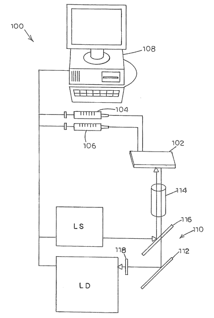
A schematic diagram of an exemplary embodiment of a microfluidic
system, generally designated 100, for generating and mixing continuous
concentration gradients of fluids is illustrated in Figure 1. System 100 can
include a microfluidic chip 102 having fluid connection to a first and second
microfluidic pump 104 and 106 for advancing fluids through chip 102 for mix
and analysis. In this embodiment, pumps 104 and 106 are syringe pumps,
-9-
CA 02618105 2008-02-07
WO 2007/024485 PCT/US2006/031053
which can be driven by servo or stepper motors. Alternatively, pumps 104 and
106 can comprise peristaltic pumps, pressure-driven pumps, conducting
polymer pumps, electro-osmotic pumps, bubble pumps, piezo-electric driven
pumps, or another type of pump suitable for pumping fluids through
microfluidic
chips. Pumps 104 and 106 can produce volumetric flow rates that are
individually controllable by a computer 108.
According to one embodiment, computer 108 can be a general-purpose
computer including a memory for storing program instructions for operating
pumps 104 and 106. Alternatively, computer 108 can include a disk drive,
compact disc drive, or other suitable component for reading instructions
contained on a computer-readable medium for operating pumps 104 and 106.
Further, computer 108 can include instructions for receiving, analyzing, and
displaying information received from detection equipment, generaily designated
110, described in further detail below. Computer 108 can also include a
display, mouse, keyboard, printer, or other suitable component known to those
of skill in the art for receiving and displaying information to an operator.
Computer 108 can operate pumps 104 and 106 to produce smooth,
continuous flows in a stable manner. As known to those of skill in the art,
some
pumps can produce volumetric flow rates as low as approximately one nanoliter
per minute. As described further herein, pumps 104 and 106 can be controlled
to produce a fluid mix at a mixing junction in microfluidic chip 102 that has
a
continuously varied ratio over time for producing continuous concentration
gradients at the mixing junction. As stated above, many sources, such as
mechanical instabilities in syringe pumps, can introduce noise into the fluid
mix
concentration.
After mixing, a fluid mixture can be advanced to a detection
channel/region, or analysis channel/region, on chip 102 and subjected to
analysis by detection equipment 110. Typically, the mixed fluids travel a
length
of channel before reaching the detection channel/region to enable passive
mixing of the fluids and sufficient interaction of the components of the
fluids,
such as reacting chemicals. The detection channel/region can include a point
at which measurement, e.g., concentration, of the fluid mixture is acquired by
a
suitable data acquisition technique. Detection equipment 110 can be operably
-10-
CA 02618105 2008-02-07
WO 2007/024485 PCT/US2006/031053
connected to computer 108 for receiving and storing the measurement acquired
from the detection channel/region. Computer 108 can also perform analysis of
measurement from detection equipment 110 and present an analysis of the
measurement to an operator in a human-readable form. After an experiment
has been run and measurement has been acquired, the fluid can flow from the
detection channel/region to any suitable waste site for proper disposal.
A microfluidic chip, such as chip 102, can comprise a central body
structure in which the various microfluidic elements are disposed. The body
structure can include an exterior portion or surface, as well as an interior
portion
which defines the various microscale channels, fluid mixing regions, and/or
chambers of the overall microscale device. For example, the body structures of
microfluidic chips typically employ a solid or semi-solid substrate that is
typically
planar in structure, i.e., substantialiy flat or having at least one flat
surface.
Suitable substrates can be fabricated from any one of a variety of materials,
or
combinations of materials. Typically, the planar substrates are manufactured
using solid substrates common in the fields of microfabrication, e.g., silica-
based substrates, such as glass, quartz, silicon, or polysilicon, as well as
other
known substrates, such as sapphire, zinc oxide alumina, Group III-V
compounds, gallium arsenide, and combinations thereof. In the case of these
substrates, common microfabrication techniques such as photolithographic
techniques, wet chemical etching, micromachining, i.e., drilling, milling and
the
like, can be readily applied in the fabrication of microfluidic devices and
substrates. Alternatively, polymeric substrates materials can be used to
fabricate the devices described herein, including, e.g., polydimethylsiloxanes
(PDMS), polymethylmethacrylate (PMMA), polyurethane, polyvinylchloride
(PVC), polystyrene polysulfone, polycarbonate, polymethylpentene,
polypropylene, polyethylene, polyvinylidine fluoride, ABS (acrylonitrile-
butadiene-styrene copolymer), cyclic olefin copolymers, and the like. In the
case of such polymeric materials, laser ablation, injection molding, or
embossing methods can be used to form the substrates having the channels
and element geometries as described herein. For injection molding and
embossing, original molds can be fabricated using any of the above described
materials and methods.
-11-
CA 02618105 2008-02-07
WO 2007/024485 PCT/US2006/031053
Channels, fluid mixing regions and chambers of microfluidic chips can be
fabricated into one surface of a planar substrate, as grooves, wells,
depressions, or other suitable configurations in that surface. A second planar
substrate, typically prepared from the same or similar material, can be
overlaid
and bonded to the first, thereby defining and sealing the channels, mixing
regions, and/or chambers of the device. Together, the upper surface of the
first
substrate, and the lower mated surface of the upper substrate, define the
interior portion of the device, i.e., defining the channels, fluid mixing
junctions,
and chambers of the device. Alternatively, the surfaces of two substrates can
be etched, embossed, or molded and mated together for defining the interior
portion of the device.
As mentioned previously, microfluidic chips typically include at least one
detection channel, also termed an analysis channel, through which fluids are
transported and subjected to a particular analysis. Fluid samples can be
advanced from their respective sources to the detection channel by placing the
fluids in channels that intersect at a fluid mixing junction. The fluids are
suitably
advanced through the channels at predetermined fluid velocities to achieve
desired concentrations of reagents at the mixing region. Additionally, the
fluid
velocities can be varied to create gradients of fluid concentration, also
known as
"concentration gradients," in which the concentration flowing out of the
mixing
region varies with time and thus with distance downstream from the mixing
region. As referred to herein, a concentration gradient is a change in the
concentration of a fluid in a space along some distance of the fluid in the
space.
As applied to microfluidic devices, for example, a concentration gradient can
be
considered the. concentration change of a fluid along a length of a microscale
channel. A concentration gradient can also be considered the concentration
change of a fluid as it passes a point over time. Typical experiments can
include varying the concentration gradients of fluids advanced to the mixing
region and observing the resulting mixed fluids at a downstream detection
channel. In order to obtain good analysis data, it is important to precisely
control the concentration gradients of fluids at the mixing region.
Unanticipated
or uncontrolled motions of the fluid can alter the shape of the resulting
concentration gradient. Even very small movements of the liquid (equaling
-12-
CA 02618105 2008-02-07
WO 2007/024485 PCT/US2006/031053
volumes of about one nanoliter for example) that would be insignificant for
larger systems can be problematic, due to the very slow flow rates used in
microfluidic devices. Similarly, diffusion of dissolved chemicals in the
liquid, or
the liquid itself, can change the concentrations of these chemicals
independent
of liquid flow. Such diffusional transport can be very important in
microfluidic
devices, due to the small spatial dimensions of and very slow flow rates in
microfluidic channels. Additionally, noise in the concentration gradient can
adversely affect analysis data. Concentration gradient noise can be observed
as a fluctuating concentration of fluid where the concentration gradient
should
be constant or smoothly changing with respect to time or space.
In the embodiment of Figure 1, detection equipment 110 can monitor the
progress of resulting reactions of the mixed fluids at the detection channel
via
fluorescence. For example, as a reaction proceeds at the detection channel:
fluorescence can increase due to generation of a fluorescent compound;
fluorescence can decrease due to degradation of a fluorescent compound;
fluorescence polarization can change due to changes in the rotational
diffusion
of a fluorescently-tagged molecule, e.g., during binding to a larger molecule;
fluorescence lifetime can change due to changes in diffusional mobility or due
to changes in chemical environment; and fluorescence wavelength (excitation
and/or emission) can change. Similarly, absorption of light by a chemical can
be measured or the reagent stream can be sent to a mass spectrometer to
measure the amount of specific chemicals.
For fluorescence detection, a fluorescence microscope can be
employed. Alternatively, any type of light path known to those of skill in the
art
can be employed. The excitation light sources can be any suitable light source
LS, such as green Helium Neon (HeNe) lasers, red diode lasers, and diode-
pumped solid state (DPSS) lasers (532 nanometers). Incandescent lamps and
mercury and xenon arclamps in combination with chromatic filters or
diffraction
gratings with slits can also be used as excitation sources. Excitation sources
can include combinations of these, for example, multiple lasers or lasers
combined with arciamps and chromatic filters and diffraction gratings with
slits.
Detection equipment 110 can include a light detector LD for detecting the
light
fluorescing from and/or passing through the detection channel/region where a
-13-
CA 02618105 2008-02-07
WO 2007/024485 PCT/US2006/031053
reaction occurs. Avalanche photodiodes (APDs) and photo-multiplier tubes
(PMTs) can also be used. Light source LS and light detector LD can be
coupled to a microscope having mirrors 112, lenses 114, dichroic reflectors
116, and chromatic filters 118. Other optical configurations can be used, such
as fiber optic delivery of light from the excitation source to the chip and
from the
sample in the chip to the photodetector.
Other methods for detection can include phosphorescence, variants of
fluorescence (e.g., polarization fluorescence, time-resolved fluorescence,
fluorescence emission spectroscopy, fluorescence (Fbrster) resonance energy
transfer), and other non-optical techniques using sensors placed into the
fluid
flow, such as pH or other ion-selective eiectrodes, conductance meters, and
capture/reporter molecules.
Computer 108 can include hardware and software computer program
products comprising computer-executable instructions embodied in computer-
readable media for controlling pumps 104 and 106. Computer 108 can also
control and analyze the measurements received from detection equipment 110.
Computer 108. can provide a user interface for presenting measurements and
analysis to an operator and receiving instructions from an operator. Certain
concepts discussed herein relate to a computer program product, for causing
computer 108 to control pumps 104 and 106, light source LS, and light detector
LD. Different methods described herein for controlling the components of
system 100 can be implemented by various computer program products. For
example, a programmable card can be used to control pumps 104 and 106,
such as a PCI-7344 Motion Control Card, available from National Instruments
Corporation, Austin, Texas. Methods for controlling pumps 104 and 106 to
achieve a desired concentration gradient and receive analysis data from
detection equipment 110 can be programmed using C++, LABVIEWTM
(available from National Instruments Corporation), or any other suitable
software. Such a computer program product comprises computer-executable
instructions and/or associated data for causing a programmable processor to
perform the methods described herein. The computer-executable instructions
can be carried on or embodied in computer-readable medium.
-14-
CA 02618105 2008-02-07
WO 2007/024485 PCT/US2006/031053
Referring to Figure 2, a schematic diagram of the channel and mixing
region layout of microfluidic chip 102 is illustrated. Microfluidic chip 102
can
include two inputs 200 and 202 connected to pumps 104 and 106 (shown in
Figure 1), respectively, for advancing fluids F and F' through the channels of
chip 102. Fluids F and F' from inputs 200 and 202, respectively, can be
advanced by pumps 104 and 106, respectively, through premixing channels
206 and 208, respectively, and combined downstream at a fluid mixing junction
210. Premixing channels 206 and 208 can also function to equilibrate the
temperature of fluids F and F' in the channels to a surrounding temperature.
In
an alternative embodiment, microfluidic chip 102 can include more than two
channels for combining more than two separate, and different if desired,
fluids
at the mixing junction or at multiple mixing junctions. The channels (such as
premixing channels 206 and 208) described herein can be circular, semi-
circular, rectangular, nearly circular, nearly semi-circular, or nearly
rectangular
in cross section.
In the embodiment of Figure 2, microfluidic chip 102 can operate as a
passive mixer such that all mixing occurs by diffusion. Therefore,
microfluidic
chip 102 can include a mixing channel 212 downstream from mixing junction
210 to allow fluids F and F' to adequateiy mix prior to detection downstream.
Alternatively, mixing can be enhanced by the inclusion of structures in the
microfluidic channels that generate chaotic advection, or mixing can be
actively
performed by the inclusion of moving, mechanical stirrers such as magnetic
beads driven by an oscillating magnetic field. Mixing junction 210 can be
configured in any suitable configuration, such as what is known as a T-
junction
as shown in Figure 2. The fluid streams from channels 206 and 208 therefore
can combine laterally towards each other.
Microfluidic chip 102 can also include a serpentine channel 214 in
communication with mixing channel 212 and positioned downstream therefrom.
Serpentine channel 214 can operate as an aging loop for allowing a reaction to
proceed for a period of time before reaching a detection channel 216. The
length of an aging loop and the linear velocity of the fluid determine the
time
period of the reaction. Longer loops and slower linear velocities produce
longer
reactions. The lengths of aging loops can be tailored to a specific reaction
or
-15-
CA 02618105 2008-02-07
WO 2007/024485 PCT/US2006/031053
set of reactions, such that the reactions have time to complete during the
length
of the channel. Conversely, long aging loops can be used and shorter reaction
times can be measured by detecting closer to mixing junction 210. Waste fluid
can be removed from microfluidic chip 102 via waste channel 204.
An exemplary method for generating and mixing concentration gradients
using microfluidic system 100 (shown in Figure 1) will now be described
hereinbelow. First, pumps 104 and 106 can be prepared with fluids and
connected to microfluidic chip 102. Any suitable method can then be used to
purge the channels of microfluidic chip 102 for removing any contaminants,
bubbles, or any other substance affecting concentration. Further,
configuration
and calibration of detection equipment 110 can be effected.
Once microfluidic system 100 has been prepared, concentration
gradients can be run through microfluidic chip 102. Pumps 104 and 106 can be
activated to establish separate flows of separate, and different if desired,
fiuids
into chip 102 for mixing and measurement. According to one embodiment, the
total or combined volumetric flow rate established by the active pumps is
maintained at a constant value during the run. In addition, the ratio of the
individual flow rates established by respective pumps can be varied over time
by individual control, thereby causing the resulting concentration gradient of
the
mixture to vary with time. The concentration gradient of interest is that of
an
analyte of interest relative to the other components of the mixture. The
analyte
of interest can be any form of reagent or component of a reagent. Exemplary
reagents can include inhibitors, substrates, enzymes, fluorophores or other
tags, and the, like. As the reaction product passes through detection
channel/region with varying concentration gradient, detection equipment 110
samples the resulting reaction flowing through at any predetermined interval.
The measurements taken of the mixture passing through the detection
channel/chamber can be temporally correlated with the flow ratio produced by
pumps 104 and 106, and a response can be plotted as a function of time and
concentration.
Figure 4 depicts one such concentration gradient. For this gradient,
pumps 104 and 106 were controlled such that the combined flow rate of the
pumps was 10 nl/min. The commands to one pump, containing buffer with a
-16-
CA 02618105 2008-02-07
WO 2007/024485 PCT/US2006/031053
fluorescent molecule (0.5 pM resorufin), are shown in trace 400. The
commands to the other pump, containing buffer without a fluorescent molecule,
are shown in trace 402. The intensity of the fluorescence measured
downstream from mixing channel 212 is shown as trace 404. Initially, pump
containing fluorophore (trace 400) was stationary for 2 minutes while the
other
pump without fluorophore flowed at 10 nl/min (trace 402), producing a low
measured fluorescence to about 190 seconds. Next, the pump without
fluorophore (trace 400) was linearly decelerated over 2 minutes to zero nl/min
as the pump with fluorophore (trace 402) was linearly accelerated to 10
nl/min,
creating a linearly increasing concentration gradient evident in the measured
fluorescence (trace 404) from about 190 to 310 seconds. Next, the pump
without fluorophore (trace 400) was held at zero nl/min, and the pump with
fluorophore (trace 402) was held at 10 ni/min, creating a maximum measured
fluorescence (trace 404) from about 190 to 320 seconds. Thus, the two pumps
were varied from 0% to 100% of the combined flow rate, creating a series of
increasing and decreasing concentration gradients. As expected, the measured
fluorescence in trace 404 matched the instructed flows in trace 400 but
temporally lagged because the measurement was made downstream from
mixing channel 212. A systematic error in the resulting concentration gradient
was evident when the expected gradient 410 was compared to the measured
fluorescence 406. A "shoulder" was present in the measured fluorescence in
which the fluorescence rose later than expected, and when it did rise,, it
rose
very rapidly to the expected fluorescence. A shoulder was also evident in the
linearly decreasing concentration gradient at reference numeral 408.
Three mechanical phenomena can cause such "shoulders" in the
resulting concentration gradient relative to the gradient expected from the
ratio
of volumetric flow rates generated by the pumps: (1) compliance-driven flow in
microfluidic chip 102 or in any fluidic component in communication with
microfluidic chip 102; (2) diffusion between fluids F and F' in premixing
channels 206 and 208, respectively, connected at mixing junction 210; and (3)
failure of pumps 104 and 106 to execute the commanded flow rate because the
precision of the pump is exceeded at flow rates at or near zero due to, for
-17-
CA 02618105 2008-02-07
WO 2007/024485 PCT/US2006/031053
example, stiction in the mechanism or insufficient resolution of the encoder
for
servomotors.
Referring again to Figure 2, compiiance can cause the volume of a
component of the microfluidic system to change as pressure changes in that
component. Pressure varies with volumetric flow rate. Volumetric flow rates
through inputs/premixing channel 200/206 and 202/208 are intentionally varied
to create the concentration gradients, so the pressure in these and all
connected components also vary. If the volume inside a component varies,
then the volumetric flow rate leaving that component also varies. For example,
if volumetric flow rate into premixing channel 206 increases, then pressure
inside this channel also increases. If premixing channel 206 expands in
response to this increased pressure, then the outflow from premixing channel
206 will be less than the inflow while premixing channel 206 expands. This
causes a temporary reduction in expected flow at mixing junction 210.
Furthermore, when the volumetric flow rate decreases, the pressure drops, and
now the volume of the compliant component decreases, causing a temporary
elevation in expected flow at mixing junction 210.
When the pressure on one side of the input junction exceeds the
pressure on the other side of the junction, then compliance on the lower
pressure side can cause fluid from the high pressure side to flow into the low
pressure side.. Referring to Figure 3A, a schematic diagram of a mixing
junction, generally designated 300, showing fluid Fl flowing out of one
channel
302 that has a higher pressure into an opposing channel 304 that has a lower
pressure. When flow in channel 302 is next increased, fluid Fl from channel
302 can be pushed out first. The result is a"shoulder" in the concentration
gradient.
A similar situation arises from diffusion which can result in "shoulders" in
the concentration gradient of mixed fluids. Referring to Figure 3B, a
schematic
diagram of a mixing junction, generally designated 306, showing diffusion
occurring between premixing channels at a mixing junction is illustrated.
Mixing
junction 306 can include a first channel 308 with a moving flow of fluid Fl
and a
second channel 310 containing a fluid F2 held stationary and adjacent to the
flow of fluid Fl from first channel 308. Fluid Fl in first channel 308
contains
-18-
CA 02618105 2008-02-07
WO 2007/024485 PCT/US2006/031053
fluorescent molecules shown flowing into a mixing channel 312. Additionally,
fluorescent molecules from first channel 308 diffuse into fluid F2 held
stationary
in second channel 310. When fluid F2 in second channel 310 is advanced to
mixing channel 312 for forming a concentration gradient, the fluorescent
molecules diffused into second channel 310 are pushed into mixing channel
312 first. The result is that the concentration gradient of fluid Fl from
first
channel 308 is not linear, as expected, at the beginning of the concentration
gradient. ' Rather, a "shoulder" forms in the concentration gradient because
of
the diffusion of the detected molecules into fluid F2 in second channel 310.
Importantly, diffusive flux of molecules also occurs from stationary fluid
F2 in channel 310 into the stream of fluid Fl flowing from channel 308. This
also can create errors in the portion of the gradient in which the
concentration
of the molecules of fluid F2 is expected to be low when the molecules of fluid
F2
diffuse into the, stream of fluid Fl effectively contaminate the flow of fluid
Fl.
This can be extremely important when the concentration of an analyte must go
to zero, as for example, when testing inhibitors of an enzyme reaction. Such
diffusion can limit the range of concentrations 'that can be mixed in a
microfluidic system. For example, if a first fluid stream contains water and a
second fluid stream contains, for example, glucose at 1 molar in water, then
diffusion of glucose from the second fluid stream into the first fluid stream
prevents the concentration of glucose from reaching zero in the mixing
channel,
for example only reaching 1 mM. Thus, diffusion effectively limits the range
of
concentration in the system to three logs of dilution (1 mM to 1 M).
Referring to Figure 4, which illustrates an exemplary graph comparing
the varying flow velocity profiles for fluids in channels 308 and 310 (shown
in
Figure 3) as generated by a first and second pump, respectiveiy, and the
resulting concentration gradient. When the first pump is at 100% and the
second pump is at 0%, the fluid in second channel 310 is held stationary.
Thus,
either fluorescent molecules from first channel 308 diffuse into the fluid in
second channel 310 when the second pump is at 0% or the fluorescent
molecules flow, due to compliance, into second channel 310. Conversely,
when the second pump output is at 100% and the first pump output is at 0%,
the result is that fluid in first channel 308 is held stationary. Now,
fluorescent
-19-
CA 02618105 2008-02-07
WO 2007/024485 PCT/US2006/031053
molecules in channel 308 diffuse into the flow from channel 310, causing the
concentration of fluorophore in first channel 308 to decrease near the
junction,
or non-fluorescent fiuid from second channel 310 flows due to compliance into
channel 308.
Graph line 404 represents the concentration gradient of fluorescent
molecules present at mixing channel 312, and detected with detection
equipment 110 (shown in Figure 1) at a point downstream from the junction. As
shown, a shoulder results from the diffusion of fluid, or flow of fluid due to
compliance, between channels 308 and 310. When the pump output
corresponding to first channel 308 increases and the pump output for second
channel 310 decreases at approximately time 590, the concentration of
fluorophore in mixing channel 312 begins to rise, as shown in line 404. It is
evident a shoulder results at approximately time 680, shown at reference
numeral 406, on the rising concentration gradient. Additionally, for example,
when the pump output corresponding to first channel 308 decreases and the
pump output for second channel 310 increases at approximately time 846, the
concentration of fluorophore in mixing channel 312 decreases. Again, a
shoulder is visibie in this decreasing concentration gradient at approximately
time 911, shown at reference numeral 408. Graph line 410 shows the desired
concentration gradient and illustrates the difference between the desired
concentration gradient (shown by graph line 410) and the actual concentration
gradient (shown by graph line 406).
Constricted Flow Portion at a Fluid Mixing Junction
As stated above, shoulders in a concentration gradient at a mixing
channel can result when fluids from one channel diffuse into another channel
at
a fluid mixing junction. Although not intended to be bound by theory, the
diffusion of the-fluid at this point can be described by Fick's law:
F=Dc A~
where F is the flux of chemical (moles=second -' ), D c is the diffusion
coefficient
(centimeter2 =second -' ), OC is the concentration difference between two
points,
and Lx is the distance between the points (thus, AC/dx is the concentration
-20-
CA 02618105 2008-02-07
WO 2007/024485 PCT/US2006/031053
gradient, moles=centimeter-3 =centimeter-' = moles=centimeter-'), and A is the
cross-sectional area, perpendicular to the gradient (in this case, the cross-
section area of channel 518 (shown in Figure 5).
Based on this equation, such diffusion can be reduced by decreasing the
cross-sectional area of the input channels near the fluid mixing junction.
This
can be accomplished in one of two ways: (1) the cross-sectional areas of the
two input channels can be made as small as possible - smaller than th'e mixing
channel; or (2) the cross-sectional area of the portion of the input channels
near
the fluid mixing junction are reduced to form a constricted flow portion. The
second approach has the advantage of minimizing the pressure drop in the
input channels and, thus, the pressure required to push fluids through
microfluidic chip 102. Additionally, if the second approach is used, then
diffusion into a channel can be reduced by increasing Ox which is accomplished
by increasing the length of the constricted portion of the channel.
Figure 5 illustrates a schematic diagram of a mixing junction, generally
designated 500, including channels having constricted flow portions for
reducing diffusion of fluid between the channels. Mixing junction 500 can be a
portion of a microfluidic chip and can include a first and second channel 502
and 504 for advancing fluids to a mixing channel 506. A first and second fluid
F
and F' can be advanced to mixing channel 506 through channels 502 and 504,
respectively, in the direction of arrows 508 and 510, respectively. Fluids F
and
F' can then mix at a mixing region 512 and advance to other elements of the
microfluidic system (not shown) in the direction of arrow 514. In an
alternative
embodiment, the mixing junction can include more than two channels including
constricted flow portions for advancing fluids F and F' to a mixing region.
As stated above, sometimes the fiuid flow velocities for fluids F and F' in
channels 502 and 504 are varied for achieving a desired concentration gradient
at mixing channel 506. When the fluid flow velocity of one of channels 502 and
504 is reduced to zero and fluid F or fluid F' is held stationary in the
channel,
fluid F or F' from the other channel can diffuse into the channel having fluid
F or
F' held stationary. Channels 502 and 504 can include constricted flow portions
516 and 518, respectively, for reducing the diffusion of fluid F or F' into
the
channel. In this embodiment, constricted flow portions 516 and 518 are
-21-
CA 02618105 2008-02-07
WO 2007/024485 PCT/US2006/031053
positioned along the length of the channels 502 and 504, respectively, near
the
junction of the ends of channels 502 and 504, respectively. Alternatively,
constricted flow portions 516 and 518 can be positioned anywhere along the
length of channels 502 and 504, respectively, for reducing diffusion of fluid
F or
F' past the constricted flow portion. Generally, the further the constricted
flow
portions are placed from the mixing junction, the lower the effectiveness of
the
constricted flow portions for reducing diffusive effects.
Constricted flow portions 516 and 518 include cross-sectional areas that
are smaller than the portions of channels 502 and 504, respectively. As shown,
portions 520 and 522 of channels 502 and 504 include cross-sectional areas
larger than constricted flow portions 516 and 518. In this embodiment, the
cross-sectional area of channels 502 and 504 generally becomes smaller as the
channel extends closer to mixing channel 506.
The length of the constricted flow portions, for example constricted flow
portions 516 and 518, can be increased to achieve reduced diffusion. As Fick's
law demonstrates, this has the effect of decreasing the concentration gradient
and, therefore, the diffusive flux. The entire microscale channel upstream of
mixing region 512 could be made similarly narrow and shallow, but this would
require much higher pressures to permit similar volumetric flow rates.
Similarly, flow into channel 518 from channel 516 driven by compliance
and a pressure difference across mixing region 512 can be minimized by
increasing resistance to flow in channel 518. Increasing the resistance to
flow
allows flow from upstream of channel 518 to fill the volume increase driven by
compliance. Decreasing the cross-sectional area and increasing the length of
channel 518 can increase the resistance to flow, as shown by the Poiseuille
equation for viscous flows.
Figure 6 illustrates an exemplary graph of a concentration gradient of
fluorescence intensity at the mixing region of a T-junction having channels
without constricted flow portions. Shoulders generated by either diffusion or
compliance are evident at reference numerals 600 and 602. Lines 604 and 606
show a portion of the expected concentration gradient. For comparison, Figure
7 shows an exemplary graph of a concentration gradient of fluorescence
intensity at a mixing region of a T-junction having constricted flow portions
and
-22-
CA 02618105 2008-02-07
WO 2007/024485 PCT/US2006/031053
subject to the same conditions as the T-junction of Figure 6. As shown,
shoulders are still evident at reference numerals 700 and 702; however, they
are made much smaller by the addition of constricted flow portions. Lines 704
and 706 show a portion of the expected concentration gradient.
Any decrease in the cross-sectional area of a channel to create a
constricted flow portion will decrease diffusive flux and compliance-driven
flow
and, thereby, reduce the magnitude of shoulders. This decrease in cross-
sectional area can be achieved by narrowing the channel, making the channel
shallower, or both.
Waste Channels
As stated above, shoulders in a concentration gradient can result when
fluids from one channel diffuse or flow into another channel at a fluid mixing
junction. As shown in Figures 3A and 3B, "contaminate" fluid is primarily
located at the end of the channel having stationary fluid. Once the fluid flow
velocity in the channel is increased, the "contaminate" fluid is pushed out of
the
channel and shoulders result. Shoulders can be reduced by removing the
"contaminate" fluid in the channel near the mixing junction prior to advancing
the fluid in the channel.
Figure 8A illustrates a schematic diagram of a mixing junction, generally
designated 800, including premixing channels 802 and 804 having connection
to waste channels 806 and 808, respectively, for removing "contaminate" fluid.
Waste channels 806 and 808 can be connected to channels 802 and 804,
respectively, at a portion near mixing channel 810.
Waste channels 806 and 808 can be operatively connected to a first and
second pump 812 and 814, respectively, for removing a desired amount of fluid
F or F' from a portion of premixing channels 802 and 804, respectively. In one
embodiment, only "contaminate" fluid is removed from premixing channels 802
and 804 without removing other "non-contaminate" fluid in the channel.
According to another embodiment, pumps 812 and 814 are controlled to
remove "contaminate" fluid from the associated waste channel 806 or 808 after
fluid in the premixing channel 802 and/or 804 has been stationary for a
predetermined time and prior to advancing fluid through the premixing channel.
-23-
CA 02618105 2008-02-07
WO 2007/024485 PCT/US2006/031053
Fluid flow out of the waste channels, relative to the reaction flow, can be
regulated passively, by fabrication with appropriate channel diameters to
control
flow resistances in the waste and premixing channels. Alternatively, flow out
of
waste channels 806 and 808 can be achieved by active valving of waste
channels 806 and 808 (on-chip or off-chip). For passive regulation, a small
percentage of total flow can always flow out of the waste channel. When, for
example, flow in channel 802 is zero and flow in channel 804 is nonzero, then
a
small flow can persist in waste channel 806. This flow can be of fluid from
the
intersection of channels 802 and 804 which is where contaminate fluid is
generated by diffusion, thus fluid flow out of 806 removes contaminate fluid.
Note that flow out of waste channel 808 can occur at this time, but it is not
contaminate. There is a small amount of non-contaminate fluid that can be lost
in the system. According to one embodiment, pumps 812 and 814 may be
excluded because pressure at the mixing point can push contaminated fluid out
through channels 806 and 808. For active valving, valves regulate the flow out
of waste channels 806 and 808 to reduce loss of fiuid out of the waste
channels. These valves open only when flow in the respective channel is at
zero, thus when flow in channel 802 goes to zero and flow in channel 804 is
nonzero, the valve regulating waste channel 806 opens while the valve
regulating waste channel 808 remains closed. For active pumping, the valves
are replaced by, or augmented by, pumps 812 and 814 on waste channels 806
and 808, respectively, that control the timing and amounts of fluid that flow
out
of the waste channels 806 and 808. Thus, when the pump controlling flow in
channel 804 stops, dropping the flow in channel 804 to zero, the pump 814
connected to waste channel 808 can turn on and pull the appropriate fluid out
of
the end of channel 804 to remove contaminated fluid. When the pump
controlling the flow in channel 804 starts again, and the flow in channel 804
rises above zero, then pump 814 can stop. Alternatively, the pump controlling
flow in channel 804 can drop not to zero, but to a flow rate that matched the
flow of pump 814 such that the flow in channel 804 matches that of channel
808.
Figure 8B illustrates a schematic diagram of a mixing junction, generally
designated 816, including premixing channels 818 and 820 having connection
-24-
CA 02618105 2008-02-07
WO 2007/024485 PCT/US2006/031053
to waste channels 822 and 824, respectively, at constricted portions 826 and
828, respectively, for removing "contaminate" fluid. Waste channels 830 and
832 can be connected to pumps 834 and 836, respectively, for advancing
"contaminate" fluid through the waste channels. Here, the flow rates in the
waste channels can be reduced, relative to those depicted in Figure 8A, owing
to the reduced diffusive flux and reduced compliance-driven flow from the
mixing junction.
Pump Strategies for Reducing Shoulders
As stated above, fluid from one channel, such as channel 206 in Figure
2, at mixing junction 210 can diffuse into the fluid in adjacent channel 208
when
the fluid in adjacent channel 208 is stationary, or compliance-driven flows
can
push fluid from channel 206 into channel 208. This will result in shoulders in
a
desired concentration gradient at mixing junction 210 when the stationary
fluid
having "contaminate" fluid is subsequently advanced to mixing junction 210.
Furthermore, shoulders can be generated when pumps 104 and 106 fails to
generate the commanded flows. Under all three of these circumstances,
shoulders can be reduced or eliminated by implementing certain pumping
strategies to advance the fluid while achieving the desired concentration
gradient runs. ,
Minimize the Time Period Fluid Flow is Held Stationary in a Channei
As stated above, when fluid in channel 208 is held stationary at mixing
junction 210, fluid from adjacent channel 206 can diffuse or flow into the
stationary fluid. The longer the fluid in channel 208 is held stationary, the
greater the amount of "contaminate" fluid and, thus, the shoulder on the
concentration gradient will be larger. The amount of "contaminate" fluid can
therefore be reduced by minimizing the time that fluid flow in channel 208 is
held stationary between advancing the fluid.
Figure 9,illustrates a graph showing an exemplary flow velocity profile for
reducing undesirable diffusion of fluid by minimizing the time that the fluid
in a
channel, such as channel 206 shown in Figure 2, at mixing junction 210 is held
stationary. The graph represents the relative flow velocity profile generated
by
-25-
CA 02618105 2008-02-07
WO 2007/024485 PCT/US2006/031053
one of two pumps, such as pump 104 shown in Figure 1, for advancing fluids
through channels 206 and 208, respectively, to mixing junction 210. Pumps
104 and 106 generate fluid flow velocities for achieving a continuous,
variable
concentration gradient at mixing junction 210. Pumps 104 and 106 can
continuously produce a total volumetric flow rate that can be kept constant.
As
shown in the graph, the relative value of the flow velocity generated by pump
104 appears "sawtooth" in shape and reaches a maximum 100% and a
minimum 0% of the total volumetric flow rate. Thus, pump 104 generates a
minimum and maximum relative flow velocity of 0% and 100%, respectively, of
the total volumetric flow rate for a minimum amount of time. The other pump,
pump 106, generates a "mirroring" flow velocity in order to achieve a combined
volumetric flow velocity of 100%. Because the flow of either pump 104 and 106
is a relative flow velocity of 0% for a minimal time, there is a minimal time
period when fluid flow in either of two channels 206 or 208 is held
stationary.
This result is achieved while still realizing a full range of concentration
gradient
over time.
Figure 10 illustrates a graph showing a series of exemplary continuous,
variable concentration gradient runs illustrating the effect of the exemplary
profile of Figure 9. Graph lines 1000 and 1002 represent the varying flow
velocity profiles generated by first and second pump 104 and 106,
respectively,
for advancing fluids through channels 206 and 208, respectively. The fluid
flow
in channels 206 and 208 reach a maximum relative flow velocity of 100% and
minimum relative flow velocity of 0%, wherein the fluid in corresponding
channel
206 or 208 is held stationary at 0%. The graph shows the relative flow
velocities being held at 0% for shorter durations for each succeeding
concentration gradient run. The next to last concentration gradient is run
with
the fluid being held stationary nearly instantaneously. Graph line 1004
represents the concentration gradient of fluorescent molecules present in
mixing channel 212 of mixing junction 210 (as detected with detection
equipment 110 shown in Figure 1) and shows that the shoulders are reduced as
the relative fluid velocity is held at 0% for shorter durations. The last
concentration gradient run shows the relative fluid velocity being held at 0%
for
a long period and that this results in shoulders again.
-26-
CA 02618105 2008-02-07
WO 2007/024485 PCT/US2006/031053
Alternatively, when mixing junction 210 is connected to more than two
premixing channels, the fluid flow velocities corresponding to each of the
channels is controlled to generate a relative value of 0% for no more than a
minimal amount of time. The combined relative fluid velocifies of all the
pumps
can be maintained at a combined 100% of the total volumetric flow rate at all
times.
Preventing the Fluid Flow Rate from Going to Zero
Shoulders at a mixing junction, such as mixing junction 210 shown in
Figure 2, can be eliminated or substantially reduced by preventing the fluid
in
any of channels 206 and 208 from being held stationary. This strategy can be
implemented by controlling pump 104 and 106, such as with computer 108, to
prevent or substantially minimize the output of pumps 104 and 106 from going
below a predetermined threshold.
This strategy can also be used to overcome stiction in the pump
mechanism and to compensate in a servo-controlled system for low encoder
resolution at flows near zero. If the pump does not go to zero flow rate, then
stiction will not occur. Similarly, if a servo-controlled pump is never driven
at
flow rates below it's precision, then the pump can produce the commanded
flow.
Figure 11 illustrates a graph showing an exemplary flow velocity profile
for eliminating or, substantially reducing undesirable diffusion of fluid by
eliminating the time that the fluid in a channel at the mixing junction is
held
stationary. The graph represents the flow velocity profile for pump 104 for
advancing fluids through channel 206 to mixing junction 210. Pumps 104 and
106 can continuously produce a total volumetric flow rate that can be kept
constant. As shown in the graph, the relative value of the flow velocity
generated by pump 104 never reaches a value less than 2%. Alternatively, the
relative flow velocity can be controlled to never generate an output less than
any predetermined amount. Pump 104 never generates a relative flow velocity
greater than 98% because the relative flow velocity generated by pump 106 is
never less than of 2% and pumps 104 and 106 generate "mirror" outputs for
generating a combined volumetric flow velocity of 100%. Because the relative
-27-
CA 02618105 2008-02-07
WO 2007/024485 PCT/US2006/031053
flow velocity is never 0%, there can be no diffusion from the fluid in channel
208
to channel 206. Similarly, this prevents the pressure difference across mixing
junction 210 from generating compliance flows. Thus, shoulders can be
eliminated by simply preventing diffusion or compliance-driven flows from
being
generated.
Alternatively, when mixing junction 210 is connected to more than two
premixing channels, the fluid flow velocities corresponding to each of the
channels is controlled to prevent the pump from generating relative flow
velocity
less than a minimal amount, such as 2%. The combined relative fluid velocities
of all the pumps can be maintained at a combined 100% of the total volumetric
flow rate at all times.
It is frequently desirable to hold the flow at 0% for a finite period of time
in one of channels 206 and 208 for the purpose of obtaining a stable baseline
reading from, for example, a biochemical reaction. Thus, if it is necessary to
get a stable measure of a chemical reaction at 0% of one reagent, for example
an enzyme inhibitor, then it is usually necessary to hold the flow of the
inhibitor
at zero to be certain that any inhibitor in the channel after mixing region
212 is
completely flushed out. If the flow must be held at zero for a duration long
enough to produce a shoulder that interferes with measurements, then one of
the following pump strategies can be applied.
Bursting the Fluid Flow
Typicaliy, when running a continuous variable concentration gradient at a
mixing junction, such as mixing junction 210 shown in Figure 2, it is desired
to
run relative flow velocities in channels 206 and 208 from 0%, or stationary,
to
100% of the combined volumetric flow velocity. As stated above, "contaminate"
fluid can diffuse or flow from one channel, one of channels 206 and 208, to
the
other when the fluid in one of the channels 206 or 208 is held stationary.
According to one pump strategy for achieving a concentration gradient having
reduced or eliminated shoulders, the "contaminate" fluid in channels 206 and
208 can be quickly ejected from one of channels 206 or 208 prior to running a
concentration gradient from a flow rate of 0% in one of channels 206 and 208.
-28-
CA 02618105 2008-02-07
WO 2007/024485 PCT/US2006/031053
This can be achieved by "bursting" the output of one of pumps 104 or 106
associated with either channel 206 or 208.
This strategy can also be used to overcome stiction in the pump
mechanism and to compensate in a servo-controlled system for low encoder
resolution at flows near zero. !f the shoulder is generated by stiction, then
the
burst in the commanded moves can start the mechanism moving, without
actually generating a pulse in the motion of the pump - the pulse is large
enough to overcome the stiction but not to accelerate the motor beyond the
desired flow rate. Similarly, the pulse can start a servo-controlled pump to
start
flowing even though the control system is receiving no instructions from the
feedback mechanism when the flow rate is below the precision of the system.
Figure 12 illustrates a graph showing an exemplary flow velocity profile
for ejecting "contaminate" fluid, or achieving the commanded flow rate, prior
to
running a concentration gradient. The graph represents the relative flow
velocity profile generated by one of two pumps, such as pumps 104 and 106
shown in Figure 1, for pumping fluids through channels, such as channels 206
and 208 shown in Figure 2, respectively, to mixing junction 210. Pumps 104
and 106 generate fluid flow velocities for achieving a continuous, variable
concentration gradient at mixing junction 210. As shown in the graph, pump
104 generates a "burst" output, indicated by reference numeral 1200, for a
predetermined period of time to eject "contaminate" fluid in channel 206 just
prior to runhing a concentration gradient from a relative flow velocity of 0%.
The concentration gradient can be run immediately after the "burst" flow to
prevent fluids from again diffusing or flowing into channel 206. The "burst"
flow
can have a maximum of approximately 20% of the total volumetric flow rate.
The "burst" flow can displace a volume that at least equals the volume of
fluid
contaminated by diffusion or flow. Thus, a more rapid or longer duration
"burst"
flow is needed if, for example, the flow in one channel is held at zero for
longer
durations or if the contaminating chemical has a larger coefficient of
diffusion or
if the temperature of the microfluidic system increases or if compliance is
larger.
The other fluid flow in channel 106 can "mirror" the relative flow velocity of
this
fluid flow for achieving a combined output of 100%, if this is desired. As
shown
-29-
CA 02618105 2008-02-07
WO 2007/024485 PCT/US2006/031053
in Figure 11, the output of pump 104 inciudes "mirror" burst f(ows, indicated
by
reference numeral 1202, for mirroring the "burst" flow of pump 106.
Figure 13 illustrates a graph showing a series of exemplary continuous,
variable concentration gradient runs for a mixing junction connected to two
premixing channels, and employing the exemplary flow profile shown in Figure
12. Graph lines 1300 and 1302 represent the varying flow velocity profiles
generated by pumps 104 and 106, respectively, for advancing fluids through
channels 206 and 208, respectively. The fluid flow in channels 206 and 208
reach a maximum relative flow velocity of 100% and minimum relative flow
velocity of 0%, wherein the fluid in the other channel, channel 206 or 208, is
held stationary at the minimum output. The graph shows "burst" flows just
prior
to the run of every other concentration gradient. The resulting concentration
gradient is indicated by graph line 1304. Ascending and descending gradients
show reduced shoulders.
Alternatively, when mixing junction 210 is connected to more than two
premixing channels, the fluid flow velocities corresponding to each of the
channels is controlled to produce a "burst" flow prior to running a
concentration
gradient. The combined relative fluid velocities of all the pumps can be
maintained at a combined 100% of the total volumetric flow rate at all times.
Slowly Flushing the Fluid
As stated above, before running a concentration gradient, any
"contaminafie" fluid can be ejected from one of channels, such as channels 206
or 208 shown in Figure 2, for reducing shoulders. According to one
embodiment, this can also be achieved by slowly flushing out one of channels
206 or 208 just prior to running the concentration gradient.
Figure 14 illustrates a graph showing an exemplary flow velocity profile
for ejecting "contaminate" fluid prior to running a concentration gradient.
The
graph represents the flow velocity profile for one of two pumps, such as pumps
104 or 106 shown in Figure 1, for advancing fluids through channels 206 or
208, shown in, Figure 1, to a mixing junction. Pumps 104 and 106 can
continuousiy produce a total volumetric flow rate that can be kept constant.
Figure 14 shows the relative value of the flow velocity generated by pump 104.
-30-
CA 02618105 2008-02-07
WO 2007/024485 PCT/US2006/031053
Pump 104 generates a shallow gradient, indicated by reference numeral 1400,
prior to running a normal concentration gradient, indicated by reference
numeral
1402, beginning at approximately 5% relative flow velocity. The shallow
gradient 1400 is run for a predetermined period sufficient to pump a volume at
least equal to the volume of the contaminate fluid. Any "contaminate" fluid is
removed from channel 206 by the shallow gradient 1400 just prior to running a
normal concentration gradient.
Alternatively, when mixing junction 210 is connected to more than two
channels, the fluid flow velocites corresponding to each of the channels is
controlled to output a shallow gradient prior to running a concentration
gradient.
The combined relative fluid velocities of all the pumps can be maintained at a
combined 100% of the total volumetric flow rate at all times.
. Additional Embodiment of a Mixing Junction
Figure 15 illustrates a schematic diagram of a mixing junction, generally
designated 1500, according to another embodiment. Mixing junction 1500 can
be a portion of a microfludic chip and can include a first and second channel
1502 and 1504 for advancing fluids to a mixing channel 1506. A first and
second fluid F. and F' can be advanced to mixing channel 1506 through
channels 1502 and 1504, respectively, in the direction of arrows 1508 and
1510, respectively. Fluids F and F' can then mix at mixing region 1512 and
advance to other elements of the microfluidic system (not shown) in the
direction of arrow 1514. To minimize diffusive flux and compliance-driven flow
from mixing junction 1512 into channels 1502 and 1504, the cross-sectional
areas of channels 1502 and 1504 are smaller than the cross-sectional area of
mixing channel 1506. In an alternative embodiment, mixing junction 1500 can
include more than two channels for advancing more than two fluids to a mixing
region.
Controlling Adsorption Effects
Adsorption of a molecule to the wall of a microfluidic channel can
sometimes present a problem in microfluidic and other miniaturized systems in
which the ratio of surface area to volume is many orders of magnitude larger
-31 -
CA 02618105 2008-02-07
WO 2007/024485 PCT/US2006/031053
than is found in more conventional approaches, such as for example,
dispensing and mixing of solutions in microtiter plates. Adsorption of
molecules
in microfluidic systems and other miniaturized devices can be a major obstacle
to miniaturization as the adsorption can affect molecule concentrations within
fluids, thereby negatively impacting data collected from the microfluidic
systems
or other miniaturized devices. Adsorption driven changes in concentration can
be especially problematic for microfluidic systems used to generate
concentration gradients.
In some embodiments, the presently disclosed subject matter provides
apparatuses and methods for using the same that can decrease the
interference of adsorption to concentration dependent measurements, such as
in biochemistry reactions including IC50 determinations, by altering the
geometry of a microfluidic channel. Although adsorption may not be eliminated,
the change in concentration caused by adsorption can be minimized. In
general terms, the effects of adsorption on measurements can be minimized by
reducing the ratio of channel surface area to fluid volume within the channel
(S/V), which also increases diffusion distances. However, as a high surface
area to volume-ratio can be an unavoidable consequence of the miniaturization
of microfluidics, the geometries provided by some embodiments of the
presently disclosed subject matter to minimize adsorption consequences are
most unexpected by persons in the field of microfluidics. The presently
disclosed subject matter provides for, in some embodiments, using large
channel diameters in regions of the microfluidic chip most affected by
adsorption of reaction components, that is, in regions where a reaction
proceeds and/or where measurements are taken. In some embodiments of the
presently disclosed subject matter, and with reference to the microfluidic
chip
embodiment shown in Figure 2, large channel diameters at a detection point of
detection channel 216 can be provided to reduce adsorption effects, as a
substitute for or in combination with serpentine channel 214 (also referred to
as
aging loop).
Turning now to Figure 16, an embodiment of a novel analysis channel of
the presently disclosed subject matter is illustrated in a top view. Figure 16
shows the direction of flow by arrows RI and R2 of two fluid reagent streams,
-32-
CA 02618105 2008-02-07
WO 2007/024485 PCT/US2006/031053
which can combine at a merge region or mixing point MP. After combining into
a merged fluid stream, the reagents within the stream can flow in a direction
indicated by arrow MR down a mixing channel MC that can be narrow to permit
rapid diffusional mixing of the reagent streams, thereby creating a merged
fluid
reagent stream. The fluid stream of reagents can then pass into an analysis
channel AC, at an inlet or inlet end IE that can have a channel diameter and a
cross-sectional area equivalent to that of mixing channel MC. The merged fluid
stream can then flow through an expansion region ER that can have a cross-
sectional area that can gradually increase and where the surface area to
volume ratio can thereby gradually decrease. The merged fluid stream can
then continue into an analysis region AR of analysis channel AC with an
enlarged cross-sectional area and a reduced surface area to volume ratio. A
reaction can be initiated by mixing of the reagent streams at the mixing point
MP. However, due to continuity of flow, the flow velocity slows dramatically
in
analysis region AR of analysis channel AC, and the majority of transit time
between mixing point MP and a detection area DA is spent in the larger
diameter analysis region AR. Measurements can be made inside this channel,
such as with confocal optics, to achieve measurements at detection area DA,
which can be located at a center axis CR of analysis region AR of analysis
channel AC. Center analysis region CR can be a region equidistant from any
channel wall W-of analysis channel AC. Thus, the fluid at center analysis
region
CR of detection area DA can be effectively "insulated" from adsorption at
channel walls W. That is, the amount of any reagents removed at channel wall
W can be too small, due to the greatly decreased surface area, and the
diffusion distance to channel wall W can be too long, due to the greatly
increased diffusion distance from center analysis region CR to channel wall W,
to greatly affect the concentration at centerline CL. The confocal optics, for
example, can reject signal from nearer channel wall W of analysis region AR,
permitting measurements to be made at center analysis region CR where the
concentration is least affected by adsorption at channel wall W.
A consequence of increasing analysis channel AC cross-section by
increasing channel diameter is that the ratio of channel surface area to fluid
volume (S/V) within the channel is decreased, relative to a narrower channel.
-33-
CA 02618105 2008-02-07
WO 2007/024485 PCT/US2006/031053
For example, to measure a reaction 3 minutes after mixing, with a volumetric
flow rate of 30 nL/min, the reaction should be measured at a point in the
channel such that a microfluidic channel section spanning from mixing point MP
to detection area DA encloses 90nL. For an analysis channel with a square
cross-section and a diameter of 25,um, this point is about 144 mm downstream
from mix point MP. This channel has a surface area of 1.44 X 10⁻⁵ square
meters, yielding a surface to volume ratio S/V equal to 1.6 X 10⁵ m-'. For a
channel with a diameter of 250 pm, the measurement is made 1.44 mm
downstream from mix point MP. This wider channel has a surface area of 1.44
X 10-6 square meters, yielding a S/V equal to 1.6 X 10⁴ m1, which is 1/10t"
the
S/V of the narrower channel. This alone can decrease ten-fold the removal of
compound per unit volume by adsorption.
This geometry change can also decrease the radial diffusive flux of
compound. Flow in these small channels is at low Reynolds number, so
diffusion from a point in the fluid is the only mechanism by which compound
concentration changes radially in a microfluidic channel. Increasing the
radius
of the channel, thereby decreasing the radial diffusive flux, therefore, means
that the concentration of compound at center analysis region CR of analysis
region AR can. be less affected by adsorption than in the smaller upstream
channels.
Thus, increasing the cross-sectional area of analysis region AR of
analysis channel AC can both decrease the amount of adsorption at the wall
per unit volume and decrease the rate of flux of compound from center analysis
region CR to any of channel walls W. Both together mean that the
concentration at center analysis region CR can decrease more slowly due to
adsorption of compound.
Further, in all embodiments, the surface area of all channels exposed to
compounds, not just analysis channel AC, can preferably be kept minimal,
especially those channels through which concentration gradients flow. This can
be accomplished by making channels as short as practicable. Additionally,
when the volume contained by a channel must be defined (e.g. where the
channel must contain a volume of 50 nL), it is best to use larger
diameters/shorter lengths wherever possible to reduce S/V.
-34-
CA 02618105 2008-02-07
WO 2007/024485 PCT/US2006/031053
Another benefit of increasing analysis channel AC cross-section by
increasing channel diameter is that the iength of the channel down which the
fluid flows can be reduced. In the example given earlier, a channel with 25,um
diameter needed to be 144 mm long to enclose 90 nl whereas the channel with
250,um diameter needed to be only 1.44 mm long. This shorter channel can be
much easier to fabricate and has a much smaller footprint on a microfluidic
chip.
Still another benefit of increasing analysis channel AC cross-section is
that it will behave like an expansion channel, which filters noise out of
chemical
concentration gradients, as disclosed in co-pending, commonly assigned U.S.
Provisional Application entitled MICROFLUIDIC SYSTEMS, DEVICES AND
METHODS FOR REDUCING NOISE GENERATED BY MECHANICAL
INSTABILITIES, U.S. Provisional Application No. 60/707,245 (Attorney Docket
No. 447/99/3/2), herein incorporated by reference in its entirety. The result
is
that signal to noise is larger in an analysis channel AC with larger cross-
section.
Figure 17A presents a cross-sectional side view of a portion of a
microfluidic chip MFC comprising mixing channel MC and analysis channel AC
depicted in Figure 16. Microfluidic chip MFC shown in Figure 17A can be
constructed by machining channels into a bottom substrate BS and enclosing
channels by bonding a top substrate TS to bottom substrate BS or otherwise
forming channels within microfluidic chip MC with bottom substrate BS and top
substrate TS being integral. In Figure 17A, only the flow of merged reagent
fluid stream having a flow direction indicated by arrow MR after mixing point
MP
is shown. Flow in a microfluidic channel can be at low Reynolds number, so the
streamline of fluid that flows along center analysis region CR of the narrower
mixing channel MC can travel at the mid-depth along entire mixing channel MC,
becoming center analysis region CR of analysis region AR of analysis channel
AC. Detection area DA can reside along center analysis region CR at a point
sufficiently far downstream of mixing channel MC to permit the reaction to
proceed to a desired degree.
Analysis channel AC can approximate a circular cross-section as closely
as possible to produce the smallest ratio of surface area to volume, and also
to
-35-
CA 02618105 2008-02-07
WO 2007/024485 PCT/US2006/031053
produce the largest diffusion distance from centerline center analysis region
CR
to a channel wall W. However, microfluidic channels may not be circular in
cross-section due to preferred manufacturing techniques. Rather, they can be
more likely square in cross-section, with the exact shape depending on the
technique used to form the channels. For such channels, a cross-section of
analysis channel AC, particularly within analysis region AR, can have an
aspect
ratio as close to one as possible or, more precisely stated, the distance from
center analysis region CR to channel wall W can be as nearly constant in all
radial directions as possible.
Figure 17B shows two different cross-sectional views along analysis
channel AC as viewed along cutlines A-A and B-B. Both cross-sectional views
illustrate an aspect ratio approximating one. That is, for cross-section A-A,
height H, of mixing channel MC is approximately equal to width W, of mixing
channel MC, such that H1/W1 approximately equals one. Comparably, for
cross-section B-B, height H2 of mixing channel MC is approximately equal to
width W2 of mixing channel MC, such that H2/W2 approximately equals one.
Figure 17B further shows that the cross-sectional area (H2 x W2) of
analysis region AR at cutline B-B, which is located at detection area DA of
analysis region AR, is significantly larger than the cross-sectional area (Hi
x
WI) of input end IE at cutline A-A. In some embodiments of the presently
disclosed subject matter, the cross-sectional area at detection area DA can be
at least twice the value of the cross-sectional area value at input end IE and
further upstream, such as in mixing channel MC. Further, in some
embodiments, the cross-sectional area at detection area DA can be between
about two times and about ten times the value of the cross-sectional area
value
at input end IE. As shown in cutline B-B of Figure 17B, detection area DA can
be positioned along center analysis region CR approximately equidistant from
each of walls W to provide maximal distance from walls W, and thereby
minimize effects of molecule adsorption to walls W. It is clear from Figure
17B
that the larger cross-sectional area at cutline B-B can provide both greater
distance from walls W and smaller S/V than the smaller cross-sectional area at
cutline A-A, both of which can reduce adsorption effects on data analysis, as
discussed herein. Although detection area DA is shown in the figures as a
-36-
CA 02618105 2008-02-07
WO 2007/024485 PCT/US2006/031053
circle having a distinct diameter, the depiction in the drawings is not
intended as
a limitation to the size, shape, and/or location of detection area DA within
the
enlarged cross-sectional area of analysis region AR. Rather, detection area DA
can be as large as necessary and shaped as necessary (e.g. circular,
elongated oval or rectangle, etc.) to acquire the desired data, while
minimizing
size as much as possible to avoid deleterious adsorption effects on the data.
Determination of the optimal balance of size, shape and location while
minimizing adsorption effects is within the capabilities of one of ordinary
skill in
the art without requiring undue experimentation.
Additional details and features of analysis channel AC are disclosed in
co-pending, commonly assigned U.S. Provisional Application entitled
METHODS AND APPARATUSES FOR REDUCING EFFECTS OF MOLECULE
ADSORPTION WITHIN MICROFLUIDIC CHANNELS, U.S. Provisional
Application No. 60/707,366 (Attorney Docket No. 447/99/8), herein
incorporated by reference in its entirety.
In some embodiments, the presently disclosed subject matter provides
apparatuses and methods for making and using the same that can decrease
the interference of adsorption to concentration dependent measurements, such
as in biochemistry reactions (including IC50 determinations), by reducing
adsorption of molecules to microfluidic channel walls. In some embodiments,
the presently disclosed subject matter provides microfluidic chips comprising
channels and chambers with treated surfaces exhibiting reduced adsorption of
molecules to channel walls, such as for example hydrophilic surfaces, and
methods of preparing and using the same. In some embodiments, methods of
preparing hydrophilic surfaces by treating hydrocarbon-based plastics, such as
for example polycarbonate, with fluorine gas mixtures are provided. In some
exemplary embodiments, the methods comprise contacting a mixture of fluorine
gas and an inert gas with the surface to be treated, then flushing the surface
with air. This treatment results in plastic surfaces of increased
hydrophilicity
(increased surface energy). Hydrophobic solutes, in particular known and
potential drug compounds, in solutions in contact with these treated
hydrophilic
plastic surfaces are less likely to be adsorbed onto the more hydrophilic
surfaces. Plastics comprising the treated surfaces are useful in providing
many
-37-
CA 02618105 2008-02-07
WO 2007/024485 PCT/US2006/031053
improved drug discovery and biochemical research devices for handling,
storing, and testing solutions containing low concentrations of hydrophobic
solutes.
Additional details and features of hydrophilic surfaces in microfluidic
systems and methods of making and using the same are disclosed in co-
pending, commonly owned U.S. Provisional Application entitled PLASTIC
SURFACES AND APPARATUSES FOR REDUCED ADSORPTION OF
SOLUTES AND METHODS OF PREPARING THE SAME, U.S. Provisional
Application No. 60/707,288 (Attorney Docket No. 447/99/9).
Further, in some embodiments of the presently disclosed subject matter,
microfluidic systems are provided comprising an anaiysis channel with an
enlarged cross-sectional area and a reduced surface area to volume ratio and
further comprising channels and chambers with hydrophilic surfaces.
It will be understood that various details of the subject matter can be
changed without departing from the scope of the subject matter. Furthermore,
the foregoing description is for the purpose of illustration only, and not for
the
purpose of limitation.
-38-