Note: Descriptions are shown in the official language in which they were submitted.
CA 02618246 2013-05-10
1
ELECTRIC LOCK THAT CAN BE OPERATED
ELECTRICALLY OR MANUALLY
BACKGROUND OF THE INVENTION
1. Field of the Invention
This invention relates to an electric lock, and more
particularly to an electric lock that can be operated either
electrically or manually.
2. Description of the Related Art
In US Patent Application Publication No. 2007/0169525, the
applicant discloses an electric lock operable either electrically
or manually to increase convenience during use. However,
protrusions of rotatable members of the electric lock experience
fast wear due to frequent contact therebetween, thereby reducing
the service life of the electric lock. Furthermore, locking and
unlocking of the electric lock cannot be controlled precisely.
SUMMARY OF THE INVENTION
The electric lock described in the following description is
durable and can be locked and unlocked precisely.
Accordingly, there is provided an electric lock comprising:
a manual operation mechanism including a rotary knob unit, a first
attracting member mounted fixedly to said rotary knob unit, a
key-operated lockset, and a lock-connecting rod connected to and
rotatable by said rotary knob unit and said key-operated lockset;
an electric control mechanism including a power source unit, a
clutch gear driven by said power source unit to rotate in two
CA 02618246 2013-05-10
2
directions, and a second attracting member mounted fixedly to
said clutch gear; and a lock housing unit for mounting with said
electric control mechanism, and a handle unit mounted on said
lock housing unit, said handle unit including a first handle
disposed rotatable on said lock housing unit and allowing said
rotary knob unit to be mounted rotatably thereon, and a second
handle disposed rotatable on said lock housing unit and allowing
said key-operated lockset to be mounted thereon; wherein, when
said clutch gear is driven by said power source unit to rotate
to align said first and second attracting members with each other,
a magnetic attraction force is generated between said first and
second attracting members to allow for co-rotation of said rotary
knob unit with said clutch gear; wherein, said first handle has
a rotation-limiting portion formed with at least one notch and
a circumferentially extending limiting slot that has a first end
and a second end in spatial communication with said notch; and
said rotary knob unit includes a rotary knob, and a hand-operated
connecting rod, said hand-operated connecting rod having a
handle-retaining portion connected to and co-rotatable with said
rotary knob, an annular mounting portion disposed around said
handle-retaining portion and allowing said first attracting
member to be mounted thereon, and a connecting portion
interconnecting said handle-retaining portion and said mounting
portion, said connecting portion being received movably within
said limiting slot in said first handle and movable between said
first end and said second end so that a maximum rotational angle
CA 02618246 2013-05-10
2a
of said hand-operated connecting rod relative to said first handle
is 900, said notch in said first handle allowing said connecting
portion to be moved into said limiting slot therethrough.
As such, since no friction occurs among rotating parts of the
electric lock, wearing of the rotating parts can be prevented,
thereby increasing the service life of the electric lock and
precision in controlling locking and unlocking of the electric
lock.
BRIEF DESCRIPTION OF THE DRAWINGS
These and other features and advantages of this invention will
become apparent in the following detailed description of the
preferred embodiments of this invention, with reference to the
accompanying drawings, in which:
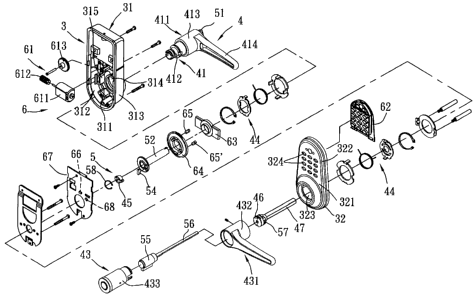
FIG. 1 is an exploded perspective view of the first preferred
embodiment of an electric lock according to this invention;
FIG. 2 is a fragmentary exploded perspective view of the first
preferred embodiment, illustrating positioning of a
hand-operated connecting rod relative to a rotary knob when the
electric lock is in an unlocking state;
FIG. 3 is a fragmentary schematic side view of the first
preferred embodiment in the unlocking state;
CA 02618246 2008-01-16
3
Fig. 4 is a fragmentary schematic side view of the first
preferred embodiment, illustrating positioning of the
hand-operated connecting rod relative to a first handle
when the electric lock is in the unlocking state;
Fig. 5 is a view similar to Fig. 3 but in a locking state;
Fig. 6 is a view similar to Fig. 2 but illustrating
positioning of the hand-operated connecting rod relative
to the rotary knob when the electric lock is in a locking
state;
Fig. 7 is a view similar to Fig. 4 but illustrating
positioning of the hand-operated connecting rod relative
to the first handle when the electric lock is in the locking
state; and
Fig. 8 is a fragmentary sectional view of the second
preferred embodiment of an electric lock according to this
invention.
DETAILED DESCRIPTION OF THE PREFERRED EMBODIMENTS
Referring to Figs. 1, 2, and 3, the first preferred
embodiment of an electric lock according to this invention
is mounted to a door (not shown) , and includes a lock housing
unit 3, a handle unit 4, a manual operation mechanism 5,
and an electric control mechanism 6.
The lock housing unit 3 includes a first lock housing
31 mounted to an inner side surface of the door, and a second
lock housing 32 mounted to an outer side surface of the
door. The first lock housing 31 has an upright wall 311,
and a surrounding wall 313 extending from a periphery of
CA 02618246 2008-01-16
4
the upright wall 311 toward the door to define an
accommodating chamber 312. The upright wall 311 has a
circular mounting hole 314 and two mounting blocks 315 (only
one is shown in Fig. 1) flanking the mounting hole 314 and
extending into the accommodating space 312. The second
lock housing 32 has an upright wall 321 and a surrounding
wall 322 extending from a periphery of the upright wall
321 toward the door. The upright wall 321 has a mounting
hole 323 and a plurality of pushbutton-receiving holes 324
located above the mounting hole 323.
The handle unit 4 includes a first handle 41 disposed
rotatably on the first lock housing 31 and extending into
the mounting hole 314, a second handle 43 disposed rotatably
on the second lock housing 32 and extending into the
mounting hole 323, two return units 44 for respectively
returning the first and second handles 41, 43, a first
connecting seat 45 sleeved on and co-rotatable with the
first handle 41, a second connecting seat 46 connected to
the second handle 43, and a handle-connecting rod 47
extending into and co-rotatable with the first and second
connecting seats 45, 46.
The first handle 41 includes a handle housing 411, and
a mounting seat 412 fixed within the handle housing 411.
The handle housing 411 has a cylindrical mounting portion
413, and a rotary lever portion 414 extending radially and
outwardly from the mounting portion 413. The mounting seat
412 has a surrounding wall 416 defining a mounting passage
CA 02618246 2008-01-16
415. The surrounding wall 416 has a rotation-limiting
portion 40 extending into the accommodating chamber 312.
The rotation-limiting portion 40 is formed with
diametrically opposed first and second notches 401, 402,
5 a
circumferentially extending limiting slot 403 having a
first end 405 and a second end 406 that is in spatial
communication with the first notch 401, and a ring-engaging
groove unit 404 disposed in proximity to an end of the
rotation-limiting portion 40.
The second handle 43 includes a handle housing 431 and
a mounting seat 433 fixed within a mounting portion 432
of the handle housing 431. The first connecting seat 45
has a central portion 451 extending into the mounting
passage 415 in the first handle 41, and two wings 452
extending respectively from two opposite sides of the
central portion 451 and engaging respectively the first
and second notches 401, 402 in the first handle 41 so as
to allow for co-rotation of the first connecting seat 45
with the first handle 41. The second connecting seat 46
is mounted rotatably within the mounting seat 433 of the
second handle 43. The handle-connecting rod 47 is
configured as a rectangular tube, and extends through a
rectangular hole 453 in the first connecting seat 45 and
into the second connecting seat 46. The handle-connecting
rod 47 can drive a spring bolt (not shown) in a known manner.
The manual operation mechanism 5 includes a rotary knob
unit 50 (see Fig. 2), a first attracting member 54 mounted
CA 02618246 2008-01-16
6
fixedly to the rotary knob unit 50, a key-operated lockset
55 mounted to the second handle 43, a lock-connecting rod
56 connected to and rotatable by the rotary knob unit 50
and the key-operated lockset 55, and an engaging plate unit
57 sleeved on and driven by the lock-connecting rod 56 to
allow for or prevent co-rotation of the second handle 43
with the lock-connecting rod 56. The rotary knob unit 50
includes a rotary knob 51 mounted rotatably on the first
handle 41, and a hand-operated connecting rod 52
co-rotatable with the rotary knob 51.
The rotary knob 51 includes a disc portion 511, an
actuation block 512 extending from the disc portion 511
in a direction away from the first handle 41 and allowing
for manual operation, a surrounding wall 513 extending from
a periphery of the disc portion 511 in a direction toward
the first handle 41, and a hole-defining wall 514 extending
from the disc portion 511 in a direction toward the first
handle 41. The surrounding wall 513 is disposed around the
hole-defining wall 514, and has two hook-engaging slots
515 (only one is shown in Fig. 2) formed radially
therethrough. The hole-defining wall 514 defines an
insert hole 516. The hand-operated connecting rod 52 has
a handle-retaining portion 521, an annular mounting portion
522 disposed around the handle-retaining portion 521, and
a connecting portion 523 interconnecting the
handle-retaining portion 521 and the annular mounting
portion 522 to thereby form a curved slot 524 between the
CA 02618246 2008-01-16
7
handle-retaining portion 521 and the annular mounting
portion 522. The handle-retaining portion 521 is formed
with two retaining hooks 525 (only one is shown in Fig.
2) engaging respectively the hook-engaging slots 515 in
the rotary knob 51 so as to allow for co-rotation of the
hand-operated connecting rod 52 with the rotary knob 51.
The annular mounting portion 522 is formed with an annular
flange 526 allowing the first attracting member 54 to be
mounted fixedly therewithin. During assembly of the
rotary knob unit 50 and the first handle 41, the connecting
portion 523 of the hand-operated connecting rod 52 is moved
into the limiting slot 403 in the rotation-limiting portion
40 of the first handle 41 via the first notch 401.
Subsequently, the retaining hooks 525 of the hand-operated
connecting rod 52 are moved respectively into the
hook-engaging slots 515 in the rotary knob 51. As such,
the connecting portion 523 is movable between the first
end 405 and second end 406 of the limiting slot 403 so that
the maximum rotational angle of the hand-operated
connecting rod 52 relative to the first handle 41 is 90 .
An end of the lock-connecting rod 56 engages fittingly the
insert hole 516 in the rotary knob 51 so as to allow for
co-rotation with the rotary knob 51. The engaging plate
unit 57 is disposed within the second connecting seat 46.
The lock-connecting rod 56 is rotatable to activate the
engaging plate unit 57 to thereby lock or unlock the
electric lock. Since such locking and unlocking
CA 02618246 2008-01-16
8
operations do not pertain to this invention, a further
description thereof will be omitted herein for the sake
of brevity. A C-shaped retaining ring 58 is received
within the ring-engaging groove unit 404 in the first handle
41 to prevent removal of the first handle 41 from the first
lock housing 31.
The electric control mechanism 6 includes a power source
unit 61 mounted within the accommodating chamber 312 in
the first lock housing 31, a pushbutton unit 62 mounted
on the second lock housing 32 and aligned with the
pushbutton-receiving holes 324, a positioning seat 63
mounted to the mounting blocks 315 of the first lock housing
31, a clutch gear 64 mounted to the positioning seat 63
and driven by the power source unit 61 to rotate in two
directions, a pair of second and third attracting members
65, 65' mounted fixedly to the clutch gear 64 and spaced
apart from each other by an angle of 1800, a circuit board
67 mounted to the first lock housing 31, a micro-switch
66 disposed on the circuit board 67, and a sensing switch
68. The power source unit 61 includes a motor 611 disposed
in the accommodating space 312 in the first lock housing
31, a worm rod 612 driven by the motor 611, and a reduction
gear 613 driven by the worm rod 612. The clutch gear 64
has a meshing portion 641 meshing with the reduction gear
613, a pair of first and second control portions 642, 642'
projecting toward the circuit board 67 and each rotatable
to contact and activate the micro-switch 66 to thereby stop
CA 02618246 2008-01-16
9
operation of the power source unit 6, and a central hole
643. The meshing portion 641 has two diametrically opposed
mounting holes 644 allowing the second and third attracting
members 65, 65' to be mounted respectively therewithin.
In this embodiment, the first, second, and third attracting
members 54, 65, 65' are magnets. Alternatively, the first
attracting member 54 or the second and third attracting
members 65, 65' may be made of a magnetically conductive
metallic material.
The lock-connecting rod 56 is configured as a plate
having a rectangular cross-section.
With further reference to Figs. 3 and 4, when the
electric lock is in an unlocking state, the lock-connecting
rod 56 is horizontal, and the connecting portion 523 of
the hand-operated connecting rod 52 is disposed at the first
end 405 of the limiting slot 403 in the first handle 41.
Furthermore, the second attracting member 65 is adjacent
to the first attracting member 54, and the first control
portion 642 of the clutch gear 64 is aligned with the
micro-switch 66. Further, the engaging plate unit 57
projects from the second connecting seat 46 to allow for
co-rotation of the second handle 43 with the
handle-connecting rod 47. In this state, when an external
force is applied to pivot one of the first and second handles
41, 43, the handle-connecting rod 47 and the other of the
first and second handles 41, 43 co-rotate therewith to move
the spring bolt. When the external force is released, the
CA 02618246 2008-01-16
first and second handles 41, 43 are returned by the return
units 44 to their original positions.
With particular reference to Figs. 1, 5, 6, and 7, the
electric lock can be locked manually by rotating the rotary
5 knob 51 or inserting a key (not shown) into the lockset
55 and rotating the key. When the rotary knob 51 is rotated
90 , the hand-operated connecting rod 52 and the
lock-connecting rod 56 co-rotate therewith to move the
connecting portion 523 of the hand-operated connecting rod
10 52 to the second end 406 of the limiting slot 403. Hence,
the lock-connecting rod 56 is rotated to a vertical position
to retract the engaging plate unit 57 into the second
connecting seat 46, thereby preventing co-rotation of the
second handle 43 with the lock-connecting rod 56 and, thus,
opening of the door through operation of the second handle
43. During rotation of the hand-operated connecting rod
52, when the lock-connecting rod 56 is rotated to the
vertical position, the first attracting member 54 is
aligned with the sensing switch 68 along a longitudinal
direction of the hand-operated connecting rod 52. When the
sensing switch 68 detects alignment of the first attracting
member 54 therewith (i.e., the locking state of the electric
lock) , a signal is emitted therefrom to the circuit board
67. Hence, if a button-pushing operation is performed on
the pushbutton unit 62 in order to lock the door, operation
of the power source unit 6 can be prevented.
Alternatively, the electric lock may be locked
CA 02618246 2008-01-16
11
electrically by operating the pushbutton unit 62 or a remote
controller (not shown) to activate the motor 611 of the
power source unit 6. When the motor 611 is activated, the
clutch gear 64 is rotated clockwise. Upon clockwise
rotation of the clutch gear 64 by 45 , the second attracting
member 65 comes into alignment with the first attracting
member 54 to generate a magnetic attraction force
therebetween, to thereby allow for subsequent co-rotation
of the hand-operated connecting rod 52 and the rotary knob
51 with the clutch gear 64. When the connecting portion
523 of the hand-operated connecting rod 52 is disposed at
the second end 406 of the limiting slot 403, the second
control portion 642' contacts and activates the
micro-switch 66 to stop operation of the power source unit
61.
To unlock the electric lock electrically, the
pushbutton unit 62 or the remote controller is operated
to rotate the clutch gear 64 counterclockwise.
To unlock the electric lock manually, the rotary knob
51 is rotated counterclockwise.
Upon counterclockwise rotation of the clutch gear 64
by 45 , the third attracting member 65' comes into alignment
with the first attracting member 54 to generate a magnetic
attraction force therebetween to thereby allow for
subsequent co-rotation of the hand-operated connecting rod
52 and the rotary knob 51 with the clutch gear 64.
Fig. 8 shows the second preferred embodiment of an
CA 02618246 2008-01-16
12
electric lock according to this invention, which is
configured as a so-called "auxiliary lock" (i.e., a lock
that does not have any handle) and which is similar in
construction to the first preferred embodiment. In this
embodiment, the rotary knob unit 50 is one piece configured
as a rotary knob, and includes an upright wall 511, an
actuation block 512, and a rotating shaft portion having
an end surface 514' formed with a cross-shaped slot 516.
The cross-shaped slot 516 has two straight slot portions
intersecting each other. The lock-connecting rod 56 has
an end engaging fittingly one of the straight slot portions
of the cross-shaped slot 516 to allow for co-rotation of
the lock-connecting rod 56 and the rotary knob unit 50.
Two first attracting members 54 are disposed fixedly
on the rotating shaft portion of the rotary knob unit 50,
and are spaced apart from each other by an angle of 180 .
The clutch gear 64 is sleeved rotatably around the rotating
shaft portion of the rotary knob unit 50. The second and
third attracting members 65, 65' are disposed fixedly in
the clutch gear 64. Each of the second and third attracting
members 65, 65' is rotatable relative to the rotary knob
unit 50 to align with the corresponding first attracting
member 54 along a radial direction of the rotary knob 51.
Since co-rotation of the clutch gear 64 with the rotary
knob unit 50 is enabled by a magnetic attraction force
generated between the first attracting member (s) 54 and
the second and third attracting members 65, 65', no friction
CA 02618246 2013-05-10
13
occurs among rotating parts of the electric lock. As a result,
wearing of the rotating parts can be prevented, thereby increasing
the service life of the electric lock and precision in controlling
locking and unlocking of the electric lock.
With this invention thus explained, it is apparent that
numerous modifications and variations can be made. The scope of
the claims should not be limited by the preferred embodiments
set forth in the examples, but should be given the broadest
interpretation consistent with the description as a whole.