Note: Descriptions are shown in the official language in which they were submitted.
CA 02618382 2008-02-06
SPECIFICATION
IONTOPHORESIS DEVICE
FIELD OF THE INVENTION
[0001] The present invention relates to an iontophoresis device. In
particular, the present invention relates to an iontophoresis device
capable of preventing or suppressing an unpreferable electrode reaction
in an electrode assembly.
BACKGROUND OF THE INVENTION
[0002] Iontophoresis involves electrically driving a drug dissociated
to plus or minus ions in a solution by means of a voltage to transdermally
transfer the drug into an organism, and has advantages such as a reduced
load to a patient and excellent controllability of the amount of the
drug to be administered.
[0003] Fig. 9 is an explanatory view showing the basic constitution
of an iontophoresis device as a device for performing the above-mentioned
iontophoresis.
[0004] As shown in the figure, the iontophoresis device includes: a
working electrode assembly 110 having an electrode 111 and a drug solution
holding portion 114 holding a solution of a drug that dissociates to
plus orminus drug ions (a drug solution) ; a non-working electrode assembly
120 having an electrode 121 and an electrolyte solution holding portion
122 holding an electrolyte solution; and an electric power source 130
with both of its terminals connected to the electrodes 111 and 121.
A voltage having the same conductivity type as that of a drug ion is
applied to the electrode 111 and a voltage having a conductivity type
opposite to that of the drug ion is applied to the electrode 121 in
a state where the drug solution holding portion 114 and the electrolyte
solution holding portion 122 are brought into contact with the skin
of an organism, whereby the drug ion is administered to the organism.
[0005] One of the problems to be solved in such iontophoresis device
is various electrode reactions occurring in the electrode assemblies
110 and 120.
[0006] For example, in the case where a drug is a cationic drug that
dissociates to plus drug ions, a hydrogen ion or an oxygen gas may be
generated at the electrode 111 and a hydroxide ion or a hydrogen gas
may be generated at the electrode 121 by the electrolysis of water.
In addition, the drug causes a chemical reaction near the electrode
111 to alter upon energization depending on the kind of the drug and
energization conditions. Furthermore, when the drug solution holding
portion 114 contains a chlorine ion, a chlorine gas or hypochlorous
acid may be generated.
[0007] Similarly, in the case where a drug is an anionic drug that
dissociates to minus drug ions, a hydroxide ion or a hydrogen gas may
be generated at the electrode 111 and a hydrogen ion or an oxygen gas
may be generated at the electrode 121 by the electrolysis of water.
In addition, the drug causes a chemical reaction near the electrode
1
CA 02618382 2008-02-06
111 to alter upon energization depending on the kind of the drug and
energization conditions. Furthermore, when the electrolyte solution
holding portion 122 contains a chlorine ion, a chlorine gas or hypochlorous
acid may be generated.
[0008] When such gas as described above is generated in the electrode
assembly 110 or 120, energization from the electrode 111 or 121 to the
drug solution or the electrolyte solution is inhibited. When a hydrogen
ion, a hydroxide ion, and hypochlorous acid are generated in the electrode
assembly 110 or 120, they transfer to a biological interface to have
a detrimental effect on an organism. In addition, the alteration of
a drug may cause unpreferable conditions such as the inability to obtain
an initial drug effect and the production of,a toxic substance.
[0009] Patent Document 1 discloses, as an iontophoresis device capable
of solving such problems as described above, an iontophoresis device
in which a silver electrode is used as an anode and a silver chloride
electrode is used as a cathode.
[0010] In the iontophoresis device, a reaction preferentially occurs,
in which silver in the anode is oxidizedby energization to become insoluble
silver chloride, while silver chloride is reduced at the cathode to
become metal silver. As a result, the generation of various gases and
the production of various ions due to such electrode reactions as described
above can be suppressed.
[0011] However, it is dif f icult to prevent the dissolution of the silver
electrode during storage of the iontophoresis device. In particular,
in the case where the device is intended for administering a cationic
drug, the number of kinds of applicable drugs is extremely limited.
In addition, a morphological change upon production of silver chloride
from the silver electrode is large. Therefore, special consideration
must be given in order to prevent such morphological change from affecting
the properties of the device. As a result, there arises a problem in
that a severe restriction is imposed on the shape of the device (for
example, a lamination structure cannot be adopted). Furthermore, the
iontophoresis device is unable to solve the problem of the alteration
of a drug upon energization.
[0012] Patent Document 2 discloses, as another iontophoresis device
capable of solving the above problems, an iontophoresis device shown
in Fig. 10.
[0013] As shown in the figure, the iontophoresis device is constituted
by: a working electrode assembly 210 including an electrode 211, an
electrolyte solution holding portion 212 holding an electrolyte solution
in contact the electrode 211, an ion exchange membrane 213 of a second
conductivity type, the ion exchange membrane 213 being placed on the
front surface side of the electrolyte solution holding portion 212,
a drug solution holding portion 214 holding a drug solution containing
a drug ion of a first conductivity type, the drug solution holding portion
214 being placed on the front surface side of the ion exchange membrane
213, and an ion exchange membrane 215 of the first conductivity type,
the ion exchange membrane 215 being placed on the front surface side
of the drug solution holding portion 214; and a non-working electrode
2
CA 02618382 2008-02-06
~ assembly 220 and an electric power source 230 similar to those shown
in Fig. 9.
[0014] In the iontophoresis device, the electrolyte solution and the
drug solution are partitioned by the second ion exchange membrane 213
of the second conductivity type. As a result, the composition of the
electrolyte solution can be selected independently of the drug solution.
Accordingly, an electrolyte solution containing no chlorine ion can
be used, and the selection of an electrolyte having a lower oxidation
or reduction potential than the electrolysis of water as the electrolyte
in the electrolyte solution can suppress the production of an oxygen
gas, a hydrogen gas, a hydrogen ion, or a hydroxide ion resulting from
the electrolysis of water. Alternatively,theuseofabufferelectrolyte
solution into which multiple kinds of electrolytes are dissolved can
suppress a change in pH due to the production of a hydrogen ion or a
hydroxide ion. Furthermore, in the iontophoresis device, the transfer
of a drug ion to the electrolyte solution holding portion is blocked
by the second ion exchange membrane, so a problem in that the drug alters
owing to a chemical reaction upon energization is solved.
[0015] On the other hand, the iontophoresis device disclosed in Patent
Document 2 is constituted by a large number of members, and each of
the electrolyte solution holding portion 212 and the drug solution holding
portion 214 must be handled in a wet state (a state with a high water
content) . Therefore, there arises a problem in that the automation of
the production of the device and the mass production of the device are
difficult or that a production cost is hardly reduced.
[0016]
Patent Document 1: US 4,744,787
Patent Document 2: JP 3040517 B
Non-Patent Document 1: "KS Kagaku Senmonsho Dodensei Kobunshi" edited
by Naoya Ogata, Kodansha, published on January, 1990
Non-PatentDocument2:"ShinZairyouseriesDodenseiKoubunshinoSaishin
Ouyou Gijutsu" written by Yukuo Kobayashi, CMC Publishing CO., LTD.,
published on July, 2004
DISCLOSURE OF INVENTION
PROBLEMS TO BE SOLVED
[0017] An objectofthepresentinventionisto provideaniontophoresis
device capable of preventing or suppressing the generation of an oxygen
gas, a chlorine gas, or a hydrogen gas in an electrode assembly.
[0018] Another object of the present invention is to provide an
iontophoresis device capable of preventing or suppressing the generation
of a hydrogen ion, a hydroxide ion, or hypochlorous acid in an electrode
assembly.
[0019] Another object of the present invention is to provide an
iontophoresisdevicecapableofpreventingorsuppressingthealteration
of a drug due to a chemical reaction upon energization.
[0020] Another object of the present invention is to provide an
iontophoresis device which is capable of preventing or suppressing the
generation of such gas or ion as described above or the alteration of
3
CA 02618382 2008-02-06
a drug and which does not cause a large morphological change to an electrode
due to energization.
[0021] Another object of the present invention is to provide an
iontophoresis device which is capable of preventing or suppressing the
generation of such gas or ion as described above or the alteration of
a drug and which has a simplified structure.
[0022] Another object of the present invention is to provide an
iontophoresis device which is capable of preventing or suppressing the
generation of such gas or ion as described above or the alteration of
a drug and the automation of the production of which or the mass production
of which is easily performed.
[0023] Another object of the present invention is to provide an
iontophoresis device which is capable of preventing or suppressing the
generation of such gas or ion as described above or the alteration of
a drug and the production cost of which can be reduced.
MEANS FOR SOLVING PROBLEMS
[0024] Accordingtooneaspectofthepresentinvention, thereisprovided
an iontophoresis device characterized by including at least one electrode
assembly having an electrode in which a doping layer made of a substance
effecting an electrochemical reaction owing to the doping or de-doping
of an ion is formed.
[0025] Inthepresentinvention,theelectrodepossessedbytheelectrode
assembly has a doping layer as a layer of a substance effecting an
electrochemical reaction owing to the doping or de-doping of an ion
(hereinafter, an electrode having such doping layer may be referred
to as the "doping electrode").
[0026] Therefore, energization from an electric power source to an
electrolyte solution or a drug solution is entirely or mostly caused
by the doping of a doping layer with an ion or the de-doping of the
ion from the layer. As a result, an electrode reaction generating a
gas such as an oxygen gas, a chlorine gas, or a hydrogen gas, or an
unpreferable ion such as a hydrogen ion, a hydroxide ion, or hypochlorous
acid can be prevented or at least reduced.
[0027] The term "effecting an electrochemical reaction owing to the
doping of an ion" refers to the fact that, when plus or minus charge
is given to a doping layer, the doping layer captures an ion charged
to the polarity opposite to the charge from an electrolyte solution
or drug solution in contact with the doping layer, and the layer is
doped with the ion (the ion binds to a substance constituting the doping
layer), so the given charge is compensated. The term "effecting an
electrochemical reaction owing to the de-doping of an ion" refers to
the fact that, when plus charge is given to the doping layer, a plus
ion with which the doping layer is doped is de-doped and released from
the doping layer, so the given charge is compensated, or the fact that,
when minus charge is given to the doping layer, a minus ion with which
the doping layer is doped is de-doped and released from the doping layer,
so the given charge is compensated.
[0028] Polyaniline, polypyrrole, polythiophene, or polyacetylene as
4
CA 02618382 2008-02-06
a conductive polymer, or a derivative of each of them, or a mixture
of them is typically used as a material for the doping layer in the
present invention. Of those, polyaniline is most preferably used.
Non-Patent Documents 1 and 2 detail the derivatives of polyaniline,
polypyrrole, polythiophene, or polyacetylene that can be used for the
doping layer of the present invention.
[0029] Variousmethodshavebeenknownasamethodofproducingaconductive
polymer or a method of forming a conductive polymer into a film. Examples
of the methods include: a method involving subjecting a powder-like
conductive polymer chemically synthesized by means of an oxidation
polymerization methodtocompression molding;amethodinvolvingbringing
a conductive polymer into an ink state by means of a polar organic solvent
such as N-methylpyrrolidone, molding the ink-like polymer, and removing
the solvent; and a method involving immersing an appropriate conductive
base material in a solution of a monomer for producing a conductive
polymer and performing electrolytic polymerization to form a conductive
polymer layer on the base material. The doping layer of the present
invention can be formed by means of any one of those arbitrary methods.
[0030] In this case, the entirety of the doping layer may be constituted
only by the conductive polymer, or the doping layer may contain a component
except the conductive polymer. For example, in ordertoimpartmechanical
strength against tear or break to the doping layer, an appropriate woven
or non-woven fabric impregnated with the conductive polymer can be used,
or the conductive polymer and an appropriate polymer binder can be blended
with each other. Alternatively, in order to improve the conductivity
of the conductive polymer, the conductive polymer can be blended with
a conductive filler such as carbon.
[0031] As described below, the conductive polymer may be doped with
a drug ion to be administered to an organism or with an ion for substituting
a drug ionwith which the first ion exchange membrane is doped. Inaddition,
the conductive polymer can be doped with an ion as an electron acceptor
or an electron donor for the purpose of improving the conductivity of
the conductive polymer.
[0032] Examples of a material that can be used for the doping layer
of the present invention except the conductive polymer include carbon
materials such as black lead and graphite.
[0033] As described below with respect to the invention according to
claim 14, the electrode assembly having the doping electrode can be
directly usedasanon-workingelectrodeassembly. Simultaneously, the
electrode assembly having the doping electrode can be used also as a
working electrode assembly by doping the doping layer with a drug ion
before use.
[0034] That is, energization is performed by applying a voltage having
the conductivity type opposite to that of a drug ion to the doping electrode
in a state where the doping layer is immersed in a drug solution containing
the drug ion at an appropriate, whereby the doping layer can be doped
with the drug ion.
[0035] In addition, the drug ion can be administered to an organism
by applying a voltage having the same conductivity type as that of the
CA 02618382 2008-02-06
= drug ion to the doping electrode in a state where the doping layer doped
with the drug ion is brought into contact with the skin of the organism.
[0036] In this case, energization from the doping electrode to the
organism is entirely or partially caused by the de-doping of the drug
ion from the doping layer to transfer to the organism. As a result,
theproduction of the above-described gasor unpreferableionisprevented
or at least reduced.
[0037] Furthermore, the doping layer doped with the drug ion functions
as an ion exchange membrane of the same conductivity type as that of
the drug ion. That is, doping the doping layer with a plus drug ion
imparts, to the doping layer, an ion exchange function of permitting
thepassageofaplusionandblockingthepassageofaminusion. Similarly,
doping the doping layer with a minus drug ion imparts, to the doping
layer, an ion exchange function of permitting the passage of a minus
ion and blocking the passage of a plus ion.
[0038] Therefore, upon administration of the drug ion to an organism,
the transfer of an organism counter ion (an ion present on the surface
of the organismor inthe organism, the ionbeing chargedto the conductivity
type opposite to that of the drug ion) to the doping layer is blocked,
whereby the amount of a current consumed can be reduced, and the efficiency
of administration of a drug can be increased.
[0039] The doping of the doping layer with the drug ion in the case
where the electrode assembly having the doping electrode is used as
a working electrode assembly in the manner as that described above may
be performed at any time during the period commencing on the stage of
the production of the iontophoresis device or the working electrode
assemblyandending onthestageimmediatelybeforeuse(theadministration
of a drug to an organism).
[0040] As described above, an iontophoresis device typically includes
a working electrode assembly holding a drug to be administered to an
organismandanon-workingelectrodeassemblyservingasacounterelectrode
of the working electrode assembly. In this case, in the iontophoresis
device of the present invention, at least one of the working electrode
assembly and the non-working electrode assembly is an electrode assembly
havingadopingelectrode,oreachoftheelectrodeassembliesispreferably
an electrode assembly having a doping electrode.
[0041] Depending on the kind of an iontophoresis device, a drug to
be administered to an organism may be held by each of two electrode
assemblies to be connected to both polarities of an electric power source
(in this case, each of both electrode assemblies serves as a working
electrode assembly and a non-working electrode assembly), or multiple
electrode assemblies may be connected to each polarity of an electric
power source. In such case, in the iontophoresis device of the present
invention, at least one of the electrode assemblies is an electrode
assembly having a doping electrode, or all the electrode assemblies
are preferably electrode assemblies each having a doping electrode.
[0042] An electrode assembly havinga doping electrode has an extremely
simple structure. Therefore, the automation of the production of an
iontophoresis device including an electrode assembly having a doping
6
CA 02618382 2008-02-06
electrode as at least one of a working electrode assembly and a non-working
electrode assembly and the mass production of the device can be easily
performed, and the production cost of the device can be significantly
reduced.
[0043] In the invention according to any one of claims 1 to 3, the
electrode assembly can further include a drug solution holding portion
holding a drug solution containing a drug ion of the first conductivity
type, the drug solution holding portion being placed on the front surface
side of the doping layer (claim 4).
[0044] Suchelectrodeassemblycanbeusedasaworkingelectrodeassembly
in an iontophoresis device. A drug ion in the drug solution holding
portion is administered to an organism by applying a voltage of the
first conductivity type to the doping electrode in a state where the
drug solution holding portion is brought into contact with the skin
of the organism.
[0045] In this case, the doping layer captures an ion of a second
conductivity type from the drug solution holding portion, and the layer
is doped with the ion, whereby energization from the doping electrode
to the drug solution holding portion occurs. Therefore, the generation
of the above-described gas or unpreferable ion can be suppressed.
[ 004 6] The doping layer can be doped with an ion of the first conductivity
type in advance. In this case, energization from the doping electrode
to the drug solution holding portion is caused by the doping with an
ion of the second conductivity type in the drug solution holding portion
and the de-doping of an ion of the first conductivity type from the
dopinglayer. It should be noted that the same holds true for the invention
according to claim 7 or the like in this respect.
[ 0047 ] The doping layer can be doped with an ion of the first conductivity
type through energization as a result of applying a voltage of the second
conductivity type to the doping electrode in a state where the doping
layer is immersed in an electrolyte solution containing an appropriate
concentration of the ion of the first conductivity type.
[0048] In the invention according to claim 4, the electrode assembly
preferably further includes a first ion exchange membrane of the first
conductivity type placed on the front surface side of the drug solution
holding portion (claim 5).
[0049] In the electrode assembly thus constituted, the drug ion in
the drug solution holding portion is administered to an organism through
the first ion exchange membrane by applying a voltage of the first
conductivity type to the doping electrode in a state where the first
ion exchange membrane is brought into contact with the skin of the organism.
[0050] In this case, an additional effect, that is, an increase in
efficiency of administration of the drug ion can be obtained because
the transfer of an organism counter ion to the drug solution holding
portion is blocked by the first ion exchange membrane.
[0051] In the invention according to claim 4 or 5, it is preferable
that:theelectrodeassemblyfurtherincludeasecondionexchangemembrane
of the second conductivity type placed on the front surface side of
the doping layer; and the drug solution holding portion be placed on
7
CA 02618382 2008-02-06
~ the front surface side of the second ion exchange membrane (claim 6)
Intheelectrodeassemblythusconstituted,adrugisadministered
to an organism in the same manner as that described above. In addition,
the alteration of the drug near the doping electrode during energization
is prevented or suppressed because the second ion exchange membrane
blocks the transfer of a drug ion to the side of the doping electrode.
[0052] In this case, the second ion exchange membrane and the doping
layer are preferably joined integrally with each other. The integral
joining can improve energization property between the doping layer and
the second ion exchange membrane and simplify the assembly work of the
electrode assembly. Therefore, the automation of the production of the
electrode assembly and the mass production of the electrode assembly
can be easily performed, or a reduction in production cost can be achieved.
[0053] The second ion exchange membrane and the doping layer can be
joined with each other by, for example, thermocompression bonding.
Alternatively, the joining can be performed by forming the doping layer
by means of any one of the above-described various methods on the second
ion exchange membrane.
[0054] In the invention according to any one of claims 1 to 3, the
electrode assembly can further include: an electrolyte solution holding
portion holding an electrolyte solution, the electrolyte solution holding
portion being placed on the front surface side of the doping layer;
and a first ion exchange membrane of the first conductivity type that
is placed on the front surface side of the electrolyte solution holding
portion and that is doped with a drug ion of the first conductivity
type (claim 7).
[0055] Suchelectrodeassemblycanbeusedasaworkingelectrodeassembly
in an iontophoresis device. A drug ion with which the first ion exchange
membrane is doped can be administered to an organism by applying a voltage
of the first conductivity type to the doping electrode in a state where
the first ion exchange membrane is brought into contact with the skin
of the organism.
[0056] Here,theelectrolytesolutionoftheelectrolytesolutionholding
portion serves to supply an ion of the first conductivity type for
substitutingthedrugioninthefirstionexchange membrane (hereinaf ter,
the ion of the first conductivity type in the electrolyte solution is
referred to as the "first electrolytic ion") and to supply an ion of
the second conductivity type with which the doping layer is to be doped
(hereinafter, the ion of the second conductivity type in the electrolyte
solution is referred to as the "second electrolytic ion").
[0057] That is, the doping layer captures the second electrolytic ion,
and the layer is doped with the ion, whereby energization from the doping
electrodetotheelectrolytesolutionholdingportionoccurs. Inaddition,
the drug ion in the first ion exchange membrane is substituted by the
first electrolytic ion from the electrolyte solution holding portion,
so it can transfer to an organism.
[0058] In the present invention, the first ion exchange membrane can
be doped with a drug ion by immersing the first ion exchange membrane
in a drug solution containing an appropriate concentration of drug ion
8
CA 02618382 2008-02-06
= = for a predetermined time period. The amount of the drug ion with which
the first ion exchange membrane is to be doped can be controlled by
adjusting the concentration of the drug ion, an immersion time, and
the number of times of immersion in this case.
[0059] When the first electrolytic ion has a mobility larger than that
of a drug ion, a higher priority may be placed on the transfer of the
first electrolytic ion to an organism than that on the transfer of the
drug ion to the organism, so the efficiency of administration of a drug
may reduce. Therefore, composition in which the first electrolytic ion
has a mobility comparable to or smaller than that of the drug ion is
preferably selected for the electrolyte solution of the electrolyte
solution holding portion. Alternatively, such reduction in efficiency
of administration as described above can be prevented by using the drug
ion as the first electrolytic ion of the electrolyte solution holding
portion.
[0060] In the present invention, the efficiency of administration of
a drug ion can be increased because the first ion exchange membrane
blocks the transfer of an organism counter ion to the electrolyte solution
holding portion. Furthermore, the efficiency of administration of the
drug ion can be additionally increased because the drug ion is held
by the first ion exchange membrane as a member to be brought into direct
contact with the skin of an organism.
[0061] In addition, the stability of the drug ion during storage is
improved, and the amount of a stabilizer, an antimicrobial agent, an
antiseptic, or the like to be used can be reduced or the storage period
of the device can be prolonged because the first ion exchange membrane
holds the drug ion by being doped with the ion (that is, the drug ion
binds to an ion exchange group in the ion exchange membrane ). In addition,
the stability of the administration of a drug can be improved because
the amount of the drug ion with which the first ion exchange membrane
is to be doped can be strictly adjusted. Furthermore, the assembly work
of the electrode assembly can be simplified because the first ion exchange
membrane with which the drug ion is doped is used instead of the drug
solution holding portion that must have been conventionally used in
awet state. Therefore, theautomationof theproductionof theelectrode
assembly and the mass production of the electrode assembly can be easily
performed, or a reduction in production cost can be achieved.
[0062] In the invention according to claim 7, it is preferable that:
the electrode assembly further include a second ion exchange membrane
of the second conductivity type placed on the front surface side of
the electrolyte solution holding portion; and the first ion exchange
membrane be placed on the front surface side of the second ion exchange
membrane (claim 8).
[0063] In such electrode assembly, a drug is administered to an organism
in the same manner as that described above. In addition, an additional
effect, that is, the prevention of the alteration of the drug upon
energization is achieved because the second ion exchange membrane blocks
the movement of a drug ion to the electrolyte solution holding portion.
[0064] It should be noted that the second ion exchange membrane to
9
CA 02618382 2008-02-06
= =
be used in the present invention must have a slightly low transport
number (for example, a transport number of 0.7 to 0.95) because the
first electrolytic ion cannot transfer to the first ion exchange membrane
in order to substitute the drug ion when the transport number of the
second ion exchange membrane is 1. However, even the use of the second
ion exchange membrane having such low transport number can sufficiently
prevent the transfer of the drug ion to the electrolyte solution holding
portion.
[0065] The term "transport number" as used herein is defined as a ratio
of a charge amount conveyed by the passage of a drug counter ion through
the second ion exchange membrane to the total charge conveyed through
the second ion exchange membrane when a voltage of the first conductivity
typeisappliedtothesideofanelectrolytesolutionheldbytheelectrolyte
solution holding portion in a state where the second ion exchange membrane
is placed between the electrolyte solution and a drug solution containing
appropriate concentrations of drugionand drug counter ion (forexample,
a drug solution used for doping the first ion exchange membrane with
the drug ion).
[0066] In the invention according to claim 8, the electrolysis of water
occurs at an interface between the first and second ion exchange membranes
insomecasesdependingonenergization conditionsandthelike. Therefore,
a semi-permeable membrane capable of permitting the passage of at least
the first electrolytic ion can be interposed between the first and second
ion exchange membranes for preventing the electrolysis.
[0067] The second ion exchange membrane in claim 8 can be replaced
with a semi-permeable membrane. Thesameeffect as that of the invention
according to claim 8 can be achieved by using, as the semi-permeable
membrane, a semi-permeable membrane having molecular weight cut-off
property with which the passage of the first electrolytic ion can be
permitted while the passage of a drug ion is blocked.
[0068] The interface between the second ion exchange membrane and the
first ion exchange membrane, each interface among the second ion exchange
membrane,thesemi-permeablemembrane,andthefirstionexchangemembrane,
and/or the interface between the semi-permeable membrane and the first
ion exchange membrane can be joined integrally by means of, for example,
thermocompression bonding. The integral joining can achieve the same
effect as that described above with respect to claim 6.
[0069] In the invention according to claim 7, it is preferable that:
the electrode assembly further include a second ion exchange membrane
of the second conductivity type placed on the front surface side of
the doping layer; and the electrolyte solution holding portion be placed
on the front surface side of the second ion exchange membrane (claim
9).
[0070] In such electrode assembly, a drug is administered to an organism
in the same manner as in the invention according to claim 7. In addition,
an additional effect, that is, the prevention of the alteration of the
druguponenergizationisachievedbecausethesecondionexchangemembrane
blocks the transfer of a drug ion to the doping electrode.
[0071] The second ion exchange membrane in claim 9 can be replaced
CA 02618382 2008-02-06
with a semi-permeable membrane. The same effect as that of the invention
according to claim 9 can be achieved by using, as the semi-permeable
membrane, a semi-permeable membrane having molecular weight cut-off
property with which the passage of the first electrolytic ion can be
permitted while the passage of a drug ion is blocked.
[0072] The interface between the doping electrode and the second ion
exchange membrane or the interface between the doping electrode and
the semi-permeable membrane can be joined integrally in the same manner
as that described above with respect to claim 6. The integral joining
can achieve the same effect as that described above with respect to
claim 6.
[0073] In the invention according to any one of claims 1 to 3, it is
preferable that: the electrode assembly further include a first ion
exchange membrane of the first conductivity type that is placed on the
front surface side of the doping layer and that is doped with a drug
ion of the first conductivity type; and the doping layer be doped with
an ion of the first conductivity type (claim 10).
[0074] Suchelectrodeassemblycanbeusedasaworkingelectrodeassembly
in an iontophoresis device. A voltage of the first conductivity type
is applied to the doping electrode in a state where the first ion exchange
membrane is brought into contact with the skin of an organism, whereby
an ion of the first conductivity type in the doping layer transfers
to the first ion exchange membrane, and a drug ion in the first ion
exchange membrane substituted by the ion transfers into the organism.
[0075] In this case, energization from the doping electrode to the
first ion exchange membrane is caused by the transfer of an ion of the
first conductivity type in the doping layer to the first ion exchange
membrane. Therefore, the generation of the above-described gas or
unpreferable ion can be suppressed.
[0076] Inthepresent invention, adrugionisadministeredtoanorganism
from the ion exchange membrane of the first conductivity type doped
with the drug ion. Accordingly, the same effects as that of the invention
according to claim 7 such as an increase in efficiency of administration
of a drug and an improvement of the stability of the drug ion are achieved.
[0077] In addition, in the present invention, the doping layer is doped
with an ion of the first conductivity type for substituting a drug ion.
Therefore, the electrolyte solution holding portion in the invention
according to claim 7 can be omitted, so the need for handling a wet
membercanbecompletelyeliminateduponassemblyoftheelectrodeassembly.
Furthermore, the assembly of the electrode assembly requires only two
members: the doping electrode and the first ion exchange membrane.
Accordingly, in the present invention, the assembly work of the electrode
assembly is extremely simplified. In addition, the automation of the
production of the electrode assembly and the mass production of the
electrode assembly can be extremely easily performed, or the production
cost of the electrode assembly can be significantly reduced.
[0078] In the present invention, the doping layer can be doped with
an ion of the first conductivity type in the same manner as that described
above with respect to claim 4, and the first ion exchange membrane can
11
CA 02618382 2008-02-06
be doped with a drug ion in the same manner as that described above
with respect to claim 7.
[0079] The ion of the first conductivity type with which the doping
layer is to be doped is preferably an ion having a mobility comparable
to or smaller than that of the drug ion owing to the same reason as
that described above with respect to claim 7.
[0080] The interface between the doping electrode and the first ion
exchange membrane can be joined integrally by means of, for example,
thermocompression bonding. The integral joining can achieve the same
effect as that described above with respect to claim 6.
[0081] In the invention according to claim 10, it is preferable that:
the electrode assembly further include a second ion exchange membrane
of the second conductivity type placed on the front surface side of
the doping layer; and the first ion exchange membrane be placed on the
front surface side of the second ion exchange membrane (claim 11).
[0082] Insuchelectrodeassembly,thesameeffectasthatoftheinvention
according to claim 10 is achieved. In addition, an additional effect,
that is, the prevention of the alteration of the drug during energization
is achieved because the second ion exchange membrane blocks the transfer
of a drug ion to the doping layer.
[0083] It should be noted that the second ion exchange membrane to
be used in the present invention has a slightly low transport number
(for example, a transport number of 0.7 to 0.95) in the same manner
as in claim 7 owing to the same reason as that described above with
respect to claim 7.
[0084] The second ion exchange membrane in the invention according
to claim 10 can be replaced with a semi-permeable membrane. The same
effect as that of the invention according to claim 10 can be achieved
by using, as the semi-permeable membrane, a semi-permeable membrane
having molecular weight cut-off property with which the passage of the
first electrolytic ion can be permitted while the passage of a drug
ion is blocked.
[0085] The interface between the doping electrode and the second ion
exchange membrane or the semi-permeable membrane and/or the interface
between the second ion exchange membrane or the semi-permeable membrane
and the first ion exchange membrane can be joined integrally by means
of, for example, thermocompression bonding. The integral joining can
achieve the same effect as that described above with respect to claim
6.
[0086] In the invention according to any one of claims 1 to 3, the
doping layer can be doped with a drug ion of the first conductivity
type (claim 12).
[0087] Suchelectrodeassemblycanbeusedasaworkingelectrodeassembly
in an iontophoresis device. A drug ion in the doping layer can be
administered to an organismby applying a voltage of the first conductivity
type to the doping electrode in a state where the doping layer is brought
into contact with the skin of the organism.
[0088] In this case, energization from the doping electrode to the
skin of the organism is caused by the de-doping of the drug ion with
12
CA 02618382 2008-02-06
= which the doping layer is doped to transfer to the organism. Therefore,
the generation of the above-described gas or unpreferable ion can be
suppressed.
[0089] With such constitution, a working electrode assembly can be
constituted by a single member (the doping electrode) . Accordingly,
aproductionstepcan besignificantlysimplified,andthe massproduction
and a reduction in production cost can be easily realized.
[0090] The doping layer doped with a drug ion of the first conductivity
type functions as an ion exchange membrane of the first conductivity
type. Therefore, the transfer of an organism counter ion to the doping
layer upon administration of a drug is blocked, so excellent property
can be obtained in terms of efficiency of administration of a drug.
[0091] The doping layer can be doped with a drug ion through energization
as a result of applying a voltage of the second conductivity type to
the doping electrode in a state where the doping layer is immersed in
a drug solution containing an appropriate concentration of drug ion.
[0092] In the invention according to any one of claims 1 to 3, the
electrode assembly can further include a first ion exchange membrane
of the first conductivity type placed on the front surface side of the
doping layer (claim 13).
[0093] Suchelectrodeassemblycanbeusedasaworkingelectrodeassembly
in an iontophoresis device by doping the first ion exchange membrane,
or the first ion exchange membrane and the doping layer, with a drug
ion. The drug ion with which the first ion exchange membrane is, or
the first ion exchange membrane and the doping layer are doped can be
administered to an organismby applying a voltage of the first conductivity
type to the doping electrode in a state where the first ion exchange
membrane is brought into contact with the skin of the organism.
[0094] The first ion exchange membrane can be doped with a drug ion
through energization as a result of applying a voltage of the second
conductivity type to the doping electrode in a state where the doping
layerisimmersedinadrugsolutioncontaininganappropriateconcentration
of drug ion.
[0095] In this case, a plus ion bound to an ion exchange group in the
first ion exchange membrane and substituted by the drug ion from the
drug solution transfers to the doping layer, so the layer is doped with
the ion. Alternatively, the doping layer is doped with the drug ion
of the drug solution as well depending on conditions for performing
the doping.
[0096] Energization fromthe doping electrode to the first ion exchange
membrane upon administration of a drug is caused by the transfer of
the plus ion or drug ion with which the doping layer is doped as described
above to the first ion exchange membrane. Therefore, the generation
of the above-described gas or unpreferable ion can be prevented. The
drug ion with which the first ion exchange membrane is doped is substituted
by an ion transferring from the doping layer, to thereby transfer to
an organism.
[0097] In the present invention, the efficiency of administration of
a drug can be increased because the first ion exchange membrane blocks
13
CA 02618382 2008-02-06
= the transfer of an organism counter ion to the doping layer.
[0098] Furthermore, in the present invention, unlike the invention
according to claim 12, no constitution is adopted, in which the doping
layerisbroughtintodirectcontactwiththeskinofanorganism. Therefore,
a drug can be safely administered even when a doping layer which is
not preferably brought into contact with the skin of an organism is
used.
[0099] In the present invention, the electrode assembly is composed
only of two members: the doping electrode and the first ion exchange
membrane. In addition, there is no need to handle a wet member upon
assembly of a working electrode assembly. Therefore, in the present
invention, the assembly work of the electrode assembly is extremely
simplified. Asa result, the automation ofthe production oftheelectrode
assembly and the mass product ion of the electrode assembly can be extremely
easily performed, or the production cost of the electrode assembly can
be significantly reduced.
[00100] The doping of the first ion exchange membrane with the drug
ion may be performed at any time during the period commencing on the
stage of the production of an iontophoresis device and ending on the
stage immediately before use (the administration of a drug to an organism) .
[0101] The interface between the doping electrode and the first ion
exchange membrane can be joined integrally by means of, for example,
thermocompression bonding. The integral joining can achieve the same
effect as that described above with respect to claim 6.
[0102] According to another aspect of the present invention, there
isprovidedaniontophoresisdeviceincluding:aworkingelectrodeassembly
holding a drug ion of a first conductivity type; and a non-working electrode
assembly as a counter electrode of the working electrode assembly,
characterized in that the non-working electrode assembly includes an
electrode in which a doping layer made of a substance effecting an
electrochemical reaction owing to the doping or de-doping of an ion
is formed (claim 14).
[0103] In such iontophoresis device, a voltage of the second conductivity
type is applied to the doping electrode of the non-working electrode
assembly upon administration of a drug, but the generation of: a gas
such as a hydrogen gas, an oxygen gas, or a chlorine gas; or an unpreferable
ion such as a hydrogen ion, a hydroxide ion, or hypochlorous acid at
the non-working electrode assembly at this time can be prevented.
[0104] That is, when the doping layer is not doped with any ion of
the second conductivity type, energization in the non-working electrode
assembly is caused by the transfer of an ion of the first conductivity
type on the skin of an organism or in the organism to the doping layer
such that the layer is doped with the ion. When the doping layer is
doped with an ion of the second conductivity type, the energization
is caused by the de-doping of the ion of the second conductivity type
from the doping layer to transfer to the side of the organism in addition
to the doping of the doping layer with the ion of the first conductivity
type.
[0105] The working electrode assembly in the present invention may
14
CA 02618382 2008-02-06
= hold a drug ion at a drug solution holding portion holding a drug solution
like the invention according to claim 4 or the like. Alternatively,
the working electrode assembly may hold the drug ion with which the
first ion exchange membrane or the doping layer is doped like the invention
according to claim 7, 10, 12, or the like. In addition, the working
electrode assembly of the present invention is not necessarily need
to have a doping electrode.
[0106] Intheinventionaccordingtoclaiml4,thenon-workingelectrode
assembly preferably further includes a third ion exchange membrane of
the first conductivity type placed on the front surface side of the
doping layer (claim 15).
[0107] Insuchelectrodeassembly, energization is performed in a state
where the third ion exchange membrane is brought into contact with the
skin of an organism. Therefore, an iontophoresis device capable of
administering a drug ion without bringing the doping layer into direct
contact with the skin is realized.
[0108] Itshould benotedthatenergizationinthenon-workingelectrode
as sembly is mainly causedby the transfer of an ion of the first conductivity
type on the skin of an organism or in the organism to the doping layer
such that the layer is doped with the ion.
[0109] In the invention according to claim 14, it is preferable that:
the no-working electrode assembly further include a third ion exchange
membrane of the second conductivity type that is placed on the front
surface side of the doping layer; and the doping layer be doped with
an ion of the second conductivity type (claim 16).
[0110] Suchelectrodeassemblyrealizesaniontophoresisdevicecapable
of administering a drug ion without bringing the doping layer into direct
contact with a skin in the same manner as in the invention according
to claim 15.
[0111] Itshould benotedthatenergizationinthenon-workingelectrode
assemblyismainlycausedbythede-dopingofanionofthesecondconductivity
type from the doping layer to transfer to the side of an organism.
[0112] The interface between the doping electrode and the third ion
exchange membrane in the invention according to claim 15 or 16 can be
joined integrally by means of, for example, thermocompression bonding.
The integral joining can achieve the same effect as that described above
with respect to claim 6.
[0113] Intheinventionaccordingto claiml4,thenon-workingelectrode
assemblycanfurtherincludeasecondelectrolytesolution holdingportion
holding an electrolyte solution, the second electrolyte solution holding
portion being placed on the front surface side of the doping layer.
In this case, energization is caused by, for example, the transfer of
the first electrolytic ion in the second electrolyte solution holding
portion to the doping layer such that the layer is doped with the ion
and the transfer of the second electrolytic ion to an organism.
[0114] It is preferable that: the doping electrode according to any
one of claims 1 to 16 further include a conductive base material; and
the doping layer be stacked on the conductive base material (claim 17) .
[0115] As described above, the conductivity of the doping layer can
CA 02618382 2008-02-06
= be improved by doping the layer with an ion as an electron acceptor
or an electron donor. Alternatively, an iontophoresis device capable
of adm'inistering a drug with improved efficiency can be realized by
placing the doping layer on the conductive base material to reduce the
surfaceresistanceofthedopingelectrodeinsuchamannerthatenergization
can be performed from the doping layer at a uniform current density.
[0116] The doping layer can be formed on the conductive base material
by means of, for example, a method involving: applying, to the conductive
basematerial,apowder-likeconductivepolymerblendedwithanappropriate
polymer binder or a solution of a conductive polymer in an appropriate
polar organic solvent; and subjecting the resultant to curing, solvent
removal, or the like, or a method involving: immersing the conductive
base material in a solution of a monomer for producing a conductive
polymer; and performing electrolytic polymerization.
[0117] In the invention according to claim 17, the conductive base
material is preferably a conductive sheet made of a carbon fiber or
carbon fiber paper (claim 18).
[0118] In this case, the doping electrode can be formed without using
a metallic member. As a result, a metal ion eluted from such metallic
member can be prevented from transferring to an organism to do harm
to the health. In addition, energization can occur from the doping
electrode at a uniform current density because the carbon fiber or carbon
fiberpaperisamaterialhavingalowsurfaceresistance. Aniontophoresis
device including an electrode assembly having enough flexibility to
follow the irregularities of the skin of an organism or the movement
of the organism can be provided because the carbon fiber or carbon fiber
paper is a material having high flexibility.
[0119] In this case, an electrode described in JP 2004-317317 A or
JP 2005-222892 A by the applicant of the present invention can be used.
[0120] That is, in the invention according to claim 18, the electrode
can further include a terminal member with carbon mixed in a polymer
matrix, the terminal member being attached to the conductive sheet (claim
19). Alternatively,theelectrodecanfurtherincludeanextensionportion
that is formed integrally with the conductive sheet and that is made
of a carbon fiber or carbon fiber paper.
[0121] The term "drug" as used herein refers to a substance which may
be ormaynot be prepared, which has a certain drug effect or pharmacological
effect, and which is applicable to an organism for purposes including
the therapy, recovery, and prevention of a disease and the promotion
and maintenance of the health.
[0122] The term "drug ion" as used herein refers to an ion which is
produced by the dissociation of a drug to ions and which is responsible
for a drug effect or a pharmacological action, and the term "drug counter
ion" as usedherein refers to a counter ion of the drug ion. The dissociation
of the drug to a drug ion may occur as a result of the dissolution of
the drug into a solvent such as water, an alcohol, an acid, or an alkali,
or may occur as a result of, for example, the application of a voltage
or the addition of an ionizing agent.
[0123] The term "skin" as used herein refers to the surface of an organism
16
CA 02618382 2008-02-06
to which a drug can be administered by iontophoresis, and includes a
mucosa in an oral cavity. The term "organism" as used herein refers
to a human being or an animal.
[0124] The term "first conductivity type" as used herein refers to
plus or minus electrical polarity, and the term "second conductivity
type" as used herein refers to the electrical polarity (minus or plus)
opposite to the first conductivity type.
[0125] Each of the first electrolytic ion and the second electrolytic
ion in the electrolyte solution of the electrolyte solution holding
portion in the present invention is not needed to be of a single kind,
and one or both of the ions may be of multiple kinds. Similarly, each
of the drug ion in the drug solution holding portion and the drug ion
with which the first ion exchange membrane or the doping layer is doped
is not needed to be of a single kind, and may be of multiple kinds.
[0126] Known examples of an ion exchange membrane include various ion
exchange membranes such as (1) a heterogenenous ion exchange membrane
obtained by: dispersing an ion exchange resin into a binder polymer;
and forming the resultant into a film through, for example, molding
under heat and (2) a homogeneous ion exchange membrane obtained by:
impregnating and filling a base material such as cloth, a net, or a
porousfilm with a solution prepared by dissolving a composition composed
of a monomer, a cross-linkable monomer, a polymerization initiator,
or the like into which an ion exchange group can be introduced or a
resin having a functional group into which an ion exchange group can
beintroducedintoasolvent; subjectingthe resultantto polymerization
or solvent removal; and subjecting the resultant to a treatment for
introducing an ion exchange group as well as an ion exchange resin formed
into a membrane shape. Any one of those arbitrary ion exchange membranes
can be used for the ion exchange membrane of the present invention.
Of those, an ion exchange membrane of a type in which the pores of a
porousfilmarefilledwithanionexchangeresinisparticularlypreferably
used.
[0127] More specifically, an ion exchange membrane into which a cation
exchange group is introduced such as a NEOSEPTA (CM-1, CM-2, CMX, CMS,
or CMB) manufactured by Tokuyama Co., Ltd can be used for the cation
exchangemembrane. An ion exchange membrane into whichananionexchange
group is introduced such as a NEOSEPTA (AM-1, AM-3, AMX, AHA, ACH, or
ACS) manufactured by Tokuyama Co. , Ltd can be used for the anion exchange
membrane.
[0128] The term "ion exchange membrane of the first conductivity type"
as used herein refers to an ion exchange membrane having a function
of selectively passing an ion of the first conductivity type. That is,
the "ion exchange membrane of the first conductivity type" is a cation
exchange membrane when the first conductivity type is plus, while the
"ion exchange membrane of the first conductivity type" is an anion exchange
membrane when the first conductivity type is minus.
[0129] Similarly, the term "ion exchange membrane of the second
conductivity type" as used herein refers to an ion exchange membrane
having a function of selectively passing an ion of the second conductivity
17
CA 02618382 2008-02-06
type. That is, the "ion exchange membrane of the second conductivity
type" is a cation exchange membrane when the second conductivity type
is plus, while the "ion exchange membrane of the second conductivity
type" is an anion exchange membrane when the second conductivity type
is minus.
[0130] Examples of a cation exchange group to be introduced into the
cation exchange membrane include a sulfonic group, a carboxylic group,
and a phosphoric group. The transport number of an ion exchange membrane
can be controlled depending on the kind of a cation exchange group to
be introduced. For example, the use of a sulfonic group as a strong
acidic group provides a cation exchange membrane having a high transport
number.
[0131] Examples of an anion exchange group to be introduced into the
anion exchange membrane include a primary amino group, a secondary amino
group, a tertiary amino group, a quaternary ammonium group, a pyridyl
group, an imidazole group, a quaternary pyridinium group, andaquaternary
imidazolium group. The transport number of an ion exchange membrane
can be controlled depending on the kind of an anion exchange group to
be introduced. For example, the use of a quaternary ammonium group or
a quaternary pyridinium group as a strong basic group provides an anion
exchange membrane having a high transport number.
[0132] Known examples of a treatment for introducing a cation exchange
groupincludevariousapproachessuchassulfonation,chlorosulfonation,
phosphonation, and hydrolysis. Known examples of a treatment for
introducing an anion exchange group include various approaches such
as amination and alkylation. The transport number of an ion exchange
membrane can be adjusted by adjusting conditions under which a treatment
for introducing an ion exchange group is performed.
[0133] In addition, the transport number of an ion exchange membrane
can be adjusted depending on, for example, the amount of an ion exchange
resin in the ion exchange membrane and the pore size of the membrane.
For example, in the case of an ion exchange membrane of a type in which
a porous film is filled with an ion exchange resin, an ion exchange
membrane obtained by filling a porous film with an ion exchange resin
at a filling ratio of preferably 5 to 95 mass%, more preferably 10 to
90 mass%, or particularly preferably 20 to 60 mass% can be used, the
porous film having formed thereon a large number of small pores having
a mean pore size of preferably 0.005 to 5.0 pm, more preferably 0.01
to 2.0 pm, or most preferably 0.02 to 0.2 pm (a mean flow pore size
measured in conformance with the bubble point method (JIS K3832-1990) )
at a porosity of preferably 20 to 95%, more preferably 30 to 90%, or
most preferably 30 to 60% and having a thickness of preferably 5 to
140 pm, more preferably 10 to 120 pm, or most preferably 15 to 55 pm.
The transport number of the ion exchange membrane can be adj usted depending
also on the mean pore size of the small pores and the porosity of the
porous film, and the filling ratio of the ion exchange resin.
[0134] The term "blocking of the passage of an ion" to be described
for an ion exchange membrane of the first conductivity type or the second
conductivity type in the specification does not always mean the blocking
18
CA 02618382 2008-02-06
of the passage of all ions. The term includes the case where, even when
the passage of an ion occurs with a certain speed, the degree of the
passage is so small that the passage of a drug ion is suppressed to
the extent that no alteration of a drug occurs near an electrode even
if the device is stored over a practically sufficient period, or the
passage of an organism counter ion is suppressed to the extent that
theefficiencyofadministration ofthedrug can besufficientlyincreased.
[0135] Similarly, the term "permission of the passage of an ion" to
be described for an ion exchange membrane of the first conductivity
type or the second conductivity type in the specification does not mean
that no restrictions are imposed on the passage of an ion. The term
includes the case where an ion is allowed to pass with a sufficiently
high speed or amount as compared to an ion having a conductivity type
opposite to that of the former ion even when the passage of the ion
is restricted to some extent.
[0136] The terms "blocking of the passage of an ion" and "permission
of the passage of an ion" to be described for a semi-permeable membrane
in the specification have the same meanings as those described above,
anddo not mean the blocking of the passage of all ions or that no restrictions
are imposed on the passage of an ion.
BREIF DESCRIPTION OF THE DRAWINGS
[0137] [Fig. 1] An explanatory view showing the schematic constitution
of an iontophoresis device according to an embodiment of the present
invention.
[Figs. 2] Figs. 2(A) to 2(D) are explanatory sectional views each showing
the constitution of a working electrode assembly of an iontophoresis
device according to an embodiment of the present invention.
[Figs. 3] Figs. 3(A) to 3(D) are explanatory sectional views each showing
the constitution of a working electrode assembly of an iontophoresis
device according to an embodiment of the present invention.
[Figs . 4] Figs. 4(A) and 4(B) are explanatory sectional views each showing
the constitution of a working electrode assembly of an iontophoresis
device according to an embodiment of the present invention.
[Figs. 5] Figs. 5(A) and5(B) are explanatory sectional views each showing
the constitution of a working electrode assembly of an iontophoresis
device according to an embodiment of the present invention.
[Figs. 6] Figs. 6(A) to 6(D) are explanatory sectional views each showing
the constitution of a non-working electrode assembly of an iontophoresis
device according to an embodiment of the present invention.
[Figs. 7] Fig. 7(A) is a plan view of an electrode to be used for an
iontophoresisdeviceaccordingtoanembodimentofthepresentinvention,
Fig. 7(B) is a sectional view taken along the line A-A of Fig. 7(A),
and Fig. 7(C) is a sectional view showing a modification of Fig. 7 (B) [Figs.
8] Fig. 8(A) is a plan view of an electrode according to another
aspect to be used for an iontophoresis device according to an embodiment
of the present invention, Fig. 8(B) is a sectional view taken along
the line A-A of Fig. 8(A), and Fig. 8(C) is a sectional view showing
a state where the electrode is housed in a container.
19
CA 02618382 2008-02-06
[Fig. 9] An explanatory view showing the constitution of a conventional
iontophoresis device.
[Fig. 10] An explanatory view showing the constitution of another
conventional iontophoresis device.
BEST MODE FOR CARRYING OUT THE INVENTION
[0138] Hereinafter, an embodiment of the present invention will be
described with reference to the drawings.
[0139] Fig.lisanexplanatory view showing the schematic constitution
of an iontophoresis device X according to the present invention.
[0140] In the following, for convenience of description, an
iontophoresisdeviceforadministeringadrugwhosedrugcomponent
dissociates to plus drug ions (for example, lidocaine
hydrochloride or morphine hydrochloride) will be exemplified.
An iontophoresis device for administering a drug whose drug
component dissociates tominus ions(forexample,ascorbicacid),
the device being capable of achieving substantially the same
effect as that of the following embodiment, can be constituted
by reversing the polarity of an electric power source, the
conductivity type of each ion exchange membrane, and the
conductivity type of an ion with which a doping layer or a cation
exchange membrane is doped in the following description.
[0141] As shown in the figure, the iontophoresis device X includes:
an electric power source 30; a working electrode assembly 10 connected
to the plus pole of the electric power source 30 via an electric supply
line 31; and a non-working electrode assembly 20 connected to the minus
pole of the electric power source 30 via an electric supply line 32.
[0142] The working electrode assembly 10/the non-working electrode
assembly 20 is a container 16/26 composed of an upper wall 16u/26u and
an outer peripheral wall 16s/26s. A space capable of housing various
structures to be described later is formed in the container 16/26, and
a lower surface 16b/26b of the container 16/26 is opened.
[0143] The container 16 or 26 can be formed of an arbitrary material
such as a plastic, but is preferably formed of a flexible material capable
of: preventing the evaporation of water from the inside of the container
and the penetration of foreign matter from the outside; and following
the irregularities of the skin of an organism or the movement of the
organism. In addition, a removable liner composed of an appropriate
material for preventing the evaporation of water and the mixing of foreign
matter during storage of the iontophoresis device X can be stuck to
the lower surface 16b/26b of the container 16/26. An adhesive layer
for improving adhesiveness to a skin upon administration of a drug can
be arranged on a lower end portion 16e/26e of the outer peripheral wall
16s/26s.
[0144] The container 16 or 26 is not necessarily arranged in the absence
of a wet member such as a drug solution holding portion or an electrolyte
solution holding portion (a member with a high water content) like working
electrode assemblies 10H to 10K and non-working electrode assemblies
20A to 20C to be described later.
CA 02618382 2008-02-06
[0145] A battery, a constantvoltage device, aconstant current device,
a constant voltage/current device, or the like can be used as the electric
power source 30. It is preferable to use a constant current device whose
current can be adjusted in the range of 0.01 to 1.0 mA/cm2, or preferably
0.01 to 0.5 mA/cm2, and which operates under safe voltage conditions,
specifically at 50 V or less, or preferably 30 V or less.
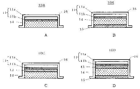
[0146] Figs. 2(A) to 2(D) are explanatory sectional views showing the
constitutions of working electrode assemblies 10A to lOD each of which
can be used as the working electrode assembly 10 of the iontophoresis
device X.
[0147] The working electrode assembly 10A includes: an electrode 11
having a conductive base material lla connected to the electric supply
line 31 and a doping layer llb formed on one surface of the base material
lla and composed of polyaniline; and a drug solution holding portion
14 holding a drug solution in contact with the doping layer llb.
[0148] The electrode 11 may include, for example, the base material
lla formed of a carbon sheet and the doping layer llb formed by applying
a polyaniline solution in which a polyaniline salt is mixed in an NMP
(N-methylpyrrolidone) solution containing PVDF (polyvinylidene
fluoride) onto the base material lla followed by drying.
[0149] 200 mg of polyaniline solution containing the polyaniline salt,
PVDF, and 14MP at the weight ratio of 1: 1: 9, in which the polyaniline
saltwaspreparedbyaddingl-Nhydrochloricacidtopolyaniline-emeraldine
base followed by filtration and drying, were applied onto the carbon
sheet having the thickness of 300 m and diameter of 17 mm. The resultant
was dried in vacuum at 100 C for 1 hour to produce the electrode 11
experimentally. The chronopotentiometry and the measurement of cyclic
voltammogram were performed using the measurement cell shown in Fig.
3 (A) .
[0150] Fig. 3(B) shows the measurement result for the capacitor
capacitance of electrode 11 under the constant current condition of
0.3 mA/cm2 by chronopotentiometry. It was confirmed that the electrode
11 had extremely large capacitor capacitance.
[0151] Fig.3(C) showsthemeasurementresultsofthecyclicvoltammogram
(a) in the case where a non-woven fabric immersedwith a solution containing
0. 9% NaCl and 2% HPC (hydroxypropyl cellulose) was used as a electrolyte
solution layer in the measurement cell and (b) in the case where a non-woven
fabric immersed with a solution containing 10% lidocaine hydrochloride
and 2% HPC was used as a electrolyte solution layer in the measurement
cell. Note that the range of potential sweep was set to -1.2 to +1.2
V in the case of (a) and the range of potential sweep was set to -0.8
to +0.8 V in the case of (b), and the potential sweep rate was set to
mV/sec in the both cases of (a) and (b) to perform the measurement.
Fig. 3(C) shows that the electrode 11 is excellent in charge and discharge
properties and has high resistance to the deterioration and the like
caused by the oxidation-reduction cycle.
[0148] The drug solution is a solution of a drug whose drug component
dissociates to plus drug ions. The drug solution holding portion 14
can hold the drug solution in a liquid state, or can hold the drug solution
21
CA 02618382 2008-02-06
by impregnating an absorbing carrier such as a gauze, filter paper,
or a gel with the drug solution.
[0149] In the working electrode assembly 10A, a plus voltage is applied
to the electrode 11 in a state where the drug solution holding portion
14 is brought into contact with the skin of an organism, whereby a drug
ion inthe drug solutionholdingportion 14 is administeredto the organism.
In this case, energization from the electrode 11 to the drug solution
holding portion 14 is entirely or partially caused by the transfer of
a minus ion in the drug solution to the doping layer llb such that the
layer is doped with the ion. Therefore, the generation of an oxygen
gas or a chlorine gas or the production of a hydrogen ion or hypochlorous
acid due to energization can be prevented or at least reduced.
[0150] The doping layer llb has a thickness of typically 10 nm to 100
pm, or particularly preferably 1 to 10 pm.
[0151] The working electrode assembly lOB includes: the electrode 11
and the drug solution holding portion 14 identical to those of the working
electrode assembly 10A; and further the cation exchange membrane 15
placed on the front surface side of the drug solution holding portion
14.
[0152] The working electrode assembly lOB achieves the same effect
as that of the working electrode assembly 10A concerning the prevention
of: the generation of a gas; or the production of an unpreferable ion
upon energization. The working electrode assembly lOB achieves an
additional effect, that is, an increase in efficiency of administration
of a drug ion because the transfer of an organism counter ion to the
drug solution holding portion 14 is blockedby the cation exchange membrane
15.
[0153] The working electrode assembly 10C includes: the electrode 11
and the drug solution holding portion 14 identical to those of the working
electrode assembly 10A; and an anion exchange membrane 13 placed between
the electrode 11 and the drug solution holding portion 14.
[0154] In the working electrode assembly lOC, energization from the
electrode 11 to the drug solution holding portion 14 is caused by the
transfer of a minus ion in the drug solution holding portion 14 to the
doping layer llb via the anion exchange membrane 13 such that the layer
is doped with the ion. Therefore, the working electrode assembly lOC
achieves the same effect as that of the working electrode assembly 10A
concerning the prevention of: the generation of a gas; or the production
of an unpreferable ion upon energization.
[0155] Furthermore, the working electrode assembly lOC achieves an
additional effect, that is, the prevention of the decomposition and
alteration of a drug upon energization because the transfer of a drug
ion in the drug solution holding portion 14 to the doping layer llb
is blocked by the anion exchange membrane 13.
[0156] The working electrode assembly lOD includes: the electrode 11
and the drug solution holding portion 14 identical to those of the working
electrode assembly 10A; the anion exchange membrane 13 placed between
the electrode 11 and the drug solution holding portion 14; and the cation
exchange membrane 15 placed on the front surface side of the drug solution
22
CA 02618382 2008-02-06
= holding portion 14.
[0157] Therefore, the working electrode assembly 10D achieves the same
effect as that of the working electrode assembly 10A concerning the
prevention of : the generation of a gas; or the production of an unpreferable
ion upon energization. The working electrode assembly 10D achieves
additional effects, that is, the prevention of the decomposition and
alteration of a drug upon energization and an increase in efficiency
of administration of the drug as in the case of the working electrode
assemblies lOB and lOC.
[0158] In each of the working electrode assemblies lOC and lOD, the
electrode 11 and the anion exchange membrane 13 can be joined and integrated
with each other by means of an approach such as thermocompression bonding.
This action can improve a state of energization from the electrode 11
to the anion exchange membrane 13 or simplify the assembly work of each
of the working electrode assemblies 10C and lOD.
[0159] Figs. 3(A) to 3(C) are explanatory sectional views showing the
constitutions of working electrode assemblies 10E to lOG according to
still another aspect each of which can be used as the working electrode
assembly 10 of the iontophoresis device X.
[0160] The working electrode assembly 10E includes: the electrode 11
identical to that of the working electrode assembly 10A; an electrolyte
solution holding portion 12 holding an electrolyte solution in contact
with the doping layer llb; and the cation exchange membrane 15 placed
on the front surface side of the electrolyte solution holding portion
12 and doped with a plus drug ion.
[0161] In the working electrode assembly 10E, a plus voltage is applied
to the electrode 11 in a state where the cation exchange membrane 15
is brought into contact with the skin of an organism, whereby the drug
ion with which the cation exchange membrane 15 is doped is administered
to the organism.
[0162] In this case, a drug can be administered with high efficiency
because the cation exchange membrane 15 blocks the transfer of an organism
counter ion to the electrolyte solution holding portion 12.
[0163] Inaddition,energizationfromtheelectrodelltotheelectrolyte
solution holding portion 12 is entirely or partially causedby the transfer
of a minus ion in the electrolyte solution to the doping layer llb such
that the layer is doped with the ion. Therefore, the generation of an
oxygen gas or a chlorine gas or the production of a hydrogen ion or
hypochlorous acid due to energi zation can be prevented or at least reduced.
[0164] Energization from the electrolyte solution holding portion 12
to the cation exchange membrane 15 is caused by the transfer of a plus
ion in the electrolyte solution holding portion 12 to the cation exchange
membrane 15 . The plus ion is substituted by a drug ion that has transferred
to an organism, to thereby bind to an ion exchange group in the cation
exchange membrane 15.
[0165] The electrolyte solution holding portion 12 of the working
electrode assembly l0E may hold the electrolyte solution in a liquid
state, or may hold the electrolyte solution by impregnating an absorbing
carrier such as a gauze, filter paper, or a gel with the electrolyte
23
CA 02618382 2008-02-06
= solution.
[0166] When a plus ion in the electrolyte solution holding portion
12 has a mobility larger than that of a drug ion, the transfer of the
plus ion to an organism preferentially may occur, so the efficiency
of administration of a drug may reduce. Therefore, the electrolyte
solution of the electrolyte solution holding portion 12 preferably has
a constitution free of a plus ion having a mobility comparable to or
larger than that of a drug ion.
[0167] The cation exchange membrane 15 can be doped with a drug ion
by immersing the cation exchange membrane 15 in a drug solution containing
an appropriate concentration of the drug ion.
[0168] The working electrode assembly lOF includes: the electrode 11,
the electrolyte solution holding portion 12, and the cation exchange
membrane 15 identical to those of the working electrode assembly lOE;
and further the anion exchange membrane 13 placed between the electrolyte
solution holding portion 12 and the cation exchange membrane 15.
[0169] The working electrode assembly 10F achieves the same effect
as that of the working electrode assembly l0E concerning the prevention
of: the generation of a gas; or the production of an unpreferable ion
upon energization. The working electrode assembly lOF achieves an
additional effect, that is, the prevention of the alteration of a drug
near the electrode 11 upon energization because the transfer of the
drug ion with which the cation exchange membrane 15 is doped to the
electrolyte solution holding portion 12 is blocked by the anion exchange
membrane 13.
[0170] Causing energization from the electrolyte solution holding
portion 12 to the cation exchange membrane 15 in the working electrode
assembly lOF requires that a plus ion in the electrolyte solution holding
portion 12 should pass through the anion exchange membrane 13 to transfer
tothecationexchangemembranel5. Therefore,ananionexchangemembrane
having a slightly low transport number is used for the anion exchange
membrane 13.
[0171] IntheworkingelectrodeassemblylOF, the electrolysis of water
occurs at an interface between the anion exchange membrane 13 and the
cation exchange membrane 15 in some cases depending on energization
conditions and the like. Therefore, a semi-permeable membrane capable
of permitting the passage of at least a plus ion in the electrolyte
solution holding portion 12 can be further placed between the anion
exchange membrane 13 and the cation exchange membrane 15 for preventing
the electrolysis. The interface between the anion exchange membrane
13 and the cation exchange membrane 15 or each interface among the anion
exchangemembranel3,thesemi-permeablemembrane,andthecationexchange
membrane 15 canbe j oined by means of an approach such as thermocompression
bonding. This action can improve energization property between them
and handleability thereof.
[0172] The anion exchange membrane 13 in the working electrode assembly
lOF permits the passage of a plus ion in the electrolyte solution holding
portion 12. Meanwhile, the same effect as that described above can be
obtainedeven when themembrane is replacedwith asemi-permeablemembrane
24
CA 02618382 2008-02-06
= capable of blocking the passage of a drug ion.
[0173] The working electrode assembly lOG includes: the electrode 11,
the electrolyte solution holding portion 12, and the cation exchange
membrane 15 identical to those of the working electrode assembly lOE;
and the anion exchange membrane 13 placed between the electrode 11 and
the electrolyte solution holding portion 12.
[0174] In the working electrode assembly lOG, energization from the
electrode 11 to the electrolyte solution holding portion 12 is caused
by the transfer of a minus ion in the electrolyte solution holding portion
12 to the doping layer via the anion exchange membrane such that the
layer is doped with the ion. Therefore, the working electrode assembly
lOG achieves the same effect as that of the working electrode assembly
10E concerning the prevention of : the generation of a gas ; or the production
of an unpreferable ion upon energization.
[0175] Energization from the electrolyte solution holding portion 12
to the cation exchange membrane 15 occurs in the same manner as in the
case of the working electrode assembly 10E. Furthermore, an additional
effect, that is, the prevention of the decomposition and alteration
of a drug upon energization is achieved because the transfer of the
drug ion with which the cation exchange membrane 15 is doped to the
doping layer llb is blocked by the anion exchange membrane 13.
[0176] The electrode 11 and the anion exchange membrane 13 are joined
and integrated with each other by means of an approach such as
thermocompression bonding, whereby energization property between them
and the handleability of them can be improved.
[0177] Figs. 4(A) and 4(B) are explanatory sectional views showing
the constitutions of working electrode assemblies 10H and 10I according
to still another aspect each of which can be used as the working electrode
assembly 10 of the iontophoresis device X.
[0178] The working electrode assembly lOH includes: the electrode 11
havingthe conductive base material lla connectedto the electric supply
line 31 and the doping layer llb formed on one surface of the base material
lla and doped with a plus ion; and the cation exchange membrane 15 placed
on the front surface side of the doping layer llb and doped with a drug
ion.
[0179] In the working electrode assembly 10H, a plus voltage is applied
to the electrode 11 in a state where the cation exchange membrane 15
is brought into contact with the skin of an organism, whereby the drug
ion with which the cation exchange membrane 15 is doped is administered
totheorganism. Asaresult,adrugcanbeadministeredwithhighefficiency
in the same manner as in the case of the working electrode assembly
10E.
[0180] In the working electrode assembly lOH, energization from the
electrode 11 to the cation exchange membrane 15 is caused by the transfer
of the plus ion with which the doping layer llb is doped to the cation
exchange membrane 15. Therefore, the generation of an oxygen gas or
a chlorine gas or the production of a hydrogen ion or hypochlorous acid
due to energization is prevented or at least reduced. The plus ion that
has transferred from the doping layer llb to the cation exchange membrane
CA 02618382 2008-02-06
= = 15 is substituted by a drug ion that has transferred to an organism,
to thereby bind to an ion exchange group in the cation exchange membrane
15.
[0181] As shown in the figure, the working electrode assembly lOH has
an extremely simple structure composed only of the electrode 11 and
the cation exchange membrane 15, and there is no need to handle a wet
member upon assembly of the working electrode assembly 10H. Therefore,
the automation of the production of the working electrode assembly 10H
and the mass production of the working electrode assembly 10H can be
extremelyeasilyperformed,andtheproductioncostoftheworkingelectrode
assembly 10 can be significantly reduced.
[0182] The electrode 11 and the cation exchange membrane 15 are joined
and integrated with each other by means of an approach such as
thermocompression bonding, whereby energization property between them
and the handleability of them can be improved.
[0183] The doping layer llb of the working electrode assembly lOH can
be doped with a plus ion through energization with the electrode 11
as a minus pole in a state where the doping layer llb is immersed in
an appropriate electrolyte solution. In addition, the cation exchange
membrane 15 can be doped with a drug ion in the same manner as that
described above with respect to the working electrode assembly 10E.
[0184] The doping layer llb is preferably doped with a plus ion having
a mobility smaller than that of a drug ion owing to the same reason
as that described above with respect to the working electrode assembly
10E. The plus ion can be a drug ion identical to or different from the
drug ion with which the cation exchange membrane 15 is doped.
[0185] The working electrode assembly 10I includes: the electrode 11
andthecationexchangemembraneidenticaltothoseoftheworkingelectrode
assembly 1OH; and the anion exchange membrane 13 placed between the
electrode 11 and the cation exchange membrane 15.
[0186] In the working electrode assembly 10I, as in the case of the
working electrode assembly lOH, the generation of an oxygen gas or a
chlorine gas or the production of a hydrogen ion or hypochlorous acid
upon administration of a drug is prevented, and there is no need to
handle a wet member upon assembly. In addition, an additional effect,
that is, the prevention of the decomposition and alteration of a drug
upon energization is achieved because the transfer of the drug ion with
which the cation exchange membrane 15 is doped to the electrolyte solution
holding portion 12 is blocked by the anion exchange membrane 13.
[0187] Causingenergizationfromtheelectrodelltothecationexchange
membrane 15 in the working electrode assembly 10I requires that the
plus ion with which the doping layer llb is doped should pass through
the anion exchange membrane 13 to transfer to the cation exchange membrane
15. Theref ore, an anion exchange membrane havingaslightlylowtransport
number is used for the anion exchange membrane 13.
[0188] The electrode 11, the anion exchange membrane 13, and the cation
exchange membrane are joined and integrated with one another by means
of an approach such as thermocompression bonding, whereby energization
property among them and the handleability of them can be improved.
26
CA 02618382 2008-02-06
[0189] The same effect as that described above can be achieved even
when the anion exchange membrane 13 in the working electrode assembly
10I is replaced with a semi-permeable membrane that blocks the passage
of a drug ion while permitting the passage of a plus ion in the electrolyte
solution holding portion 12.
[0190] Figs. 5(A) and 5(B) are explanatory sectional views showing
the constitutions of working electrode assemblies lOJ and 10K according
to still another aspect each of which can be used as the working electrode
assembly 10 of the iontophoresis device X.
[0191] The working electrode assembly 10J includes the electrode 11
having the conductive base material lla connected to the electric supply
line 31 and the doping layer llb formed on one surface of the base material
lla.
[0192] In the working electrode assembly 10J, the doping layer llb
is doped with a drug ion, and then a plus voltage is applied to the
electrode 11 in a state where the doping layer llb is brought into contact
with the skin of an organism, whereby the drug ion with which the doping
layer llb is doped is administered to the organism.
[0193] Energization from the doping layer llb to the skin of the organism
is caused by the movement of the drug ion. Therefore, the generation
of an oxygen gas or a chlorine gas or the production of a hydrogen ion
or hypochlorous acid due to energization is prevented or at least reduced.
[0194] In addition, the doping layer llb doped with the drug ion as
a plus ion has a cation exchange function, so the transfer of an organism
counter ion from the side of the skin to the doping layer llb upon
administration of a drug is blocked and the drug can be administered
with high efficiency.
[0195] As shown in the figure, the working electrode assembly 10J has
anextremelysimplestructurecomposedonlyoftheelectrodell. Therefore,
the automation of the production of the working electrode assembly lOJ
and the mass production of the working electrode assembly lOJ can be
extremelyeasilyperformed,andtheproductioncostoftheworkingelectrode
assembly can be significantly reduced.
[0196] The doping layer llb can be doped with the drug ion through
energization with the electrode 11 as a minus pole in a state where
thedopinglayerllbisimmersedinadrugsolutioncontaininganappropriate
concentration of drug ion. The doping may be performed at the stage
of the production of the iontophoresis device X or the working electrode
assembly lOJ, or may be performed immediately before the administration
of a drug.
[0197] The working electrode assembly 10K includes: the electrode 11
havingthe conductive base material lla connectedto the electric supply
line 31 and the doping layer llb formed on one surface of the base material
lla; and the cation exchange membrane 15 placed on the front surface
side of the electrode 11.
[0198] IntheworkingelectrodeassemblylOK,thecationexchangemembrane
15 is, or the cation exchange membrane 15 and the doping layer llb are
doped with a drug ion, and then a plus voltage is applied to the electrode
11 in a state where the cation exchange membrane 15 is brought into
27
CA 02618382 2008-02-06
contact with the skin of an organism, whereby the drug ion with which
the cation exchange membrane 15 is, or the cation exchange membrane
15 and the doping layer llb are doped is administered to the organism
via the cation exchange membrane 15.
[0199] In the working electrode assembly 10K, energization from the
electrode 11 to the cation exchange membrane 15 is caused by the transfer
of the ion with the doping layer llb is doped to the cation exchange
membrane. Therefore, the generation of an oxygen gas or a chlorine gas
or the production of a hydrogen ion or hypochlorous acid due to energi zation
is prevented or at least reduced.
[0200] In addition, the drug can be administered with high efficiency
because the transfer of an organism counter ion from an organism to
the doping layer llb is blocked by the cation exchange membrane 15.
[0201] The working electrode assembly 10K has an extremely simple
structure composed only of the electrode 11 and the cation exchange
membrane 15. Therefore, the automation of the production of the working
electrode assembly 10K and the mass production of the working electrode
assembly 10K can be extremely easily performed, and the production cost
of the working electrode assembly can be significantly reduced.
[0202] In addition, the working electrode assembly 10K is structured
in such a manner that the doping layer llb does not directly contact
with a skin. Therefore, a drug can be administered with no possibility
that harm or the like is done to the health of an organism even when
the doping layer llb made of a substance which is not preferably brought
into contact with the organism is used.
[0203] The cation exchange membrane 15, or the cation exchange membrane
15 and the doping layer llb, can be doped with the drug ion through
energization with the electrode 11 as a minus pole in a state where
the cation exchange membrane 15 is immersed in a drug solution containing
an appropriate concentration of drug ion. The doping may be performed
at the stage of the production of the iontophoresis device X or the
working electrode assembly 10K, or may be performed immediately before
the administration of a drug.
[ 0204 ] The electrode 11 and the cation exchange membrane 15 are joined
and integrated with each other by means of an approach such as
thermocompression bonding, whereby energization property between them
and the handleability of them can be improved.
[0205] Figs. 6(A) to 6(D) are explanatory sectional views showing the
constitutions of non-working electrode assemblies 20A and 20D each of
which can be used as the non-working electrode assembly 20 of the
iontophoresis device X.
[0206] The non-working electrode assembly 20A includes an electrode
21 having a conductive base material 21a connected to the electric supply
line 32 and a doping layer 21b formed on the base material 21a.
[0207] In the non-working electrode assembly 20A, when a minus voltage
is applied to the electrode 21 in a state where the doping layer 21b
is brought into contact with an organism, energization is caused by
the transfer of a plus ion from the skin of the organism to the doping
layer 21b such that the layer is doped with the ion. Therefore, the
28
CA 02618382 2008-02-06
generation of a hydrogen gas or the production of a hydroxide ion upon
energization is prevented or at least reduced.
[0208] When a layer doped with a minus ion in advance is used as the
doping layer 21b of the non-working electrode assembly 20A, energization
is caused by the transfer of the minus ion to the skin of an organism
and the transfer of a plus ion from the skin of the organism to the
doping layer 21b. Even in this case, the generation of a hydrogen gas
or the production of a hydroxide ion is prevented or at least reduced.
[0209] The non-working electrode assembly 20A has the same constitution
as that of the working electrode assembly 10I, so the non-working electrode
assembly 20A and the working electrode assembly 10J can be produced
by means of the same process. As a result, the production process of
an iontophoresis device can be significantly simplified. In addition,
the automation of the production of the iontophoresis device and the
mass production of the iontophoresis device can be easily performed,
and the production cost of the iontophoresis device can be significantly
reduced.
[0210] The non-working electrode assembly 20B has the electrode 21
identical to that of the non-working electrode assembly 20A and a cation
exchange membrane 25C placed on the front surface side of the doping
layer 21b.
[0211] Inthenon-workingelectrodeassembly20B,energizationiscaused
by the transfer of a plus ion from the skin of an organism to the doping
layer 21b via the cation exchange membrane 25C such that the layer is
doped with the ion. Therefore, the generation of a hydrogen gas or the
production of a hydroxide ion upon energization is prevented or at least
reduced.
[0212] Inaddition,thenon-workingelectrodeassembly20Bisstructured
in such a manner that the doping layer 21b does not directly contact
with a skin. Therefore, a drug can be safely administered even when
the doping layer 21b made of a substance which is not preferably brought
into contact with an organism is used.
[0213] The electrode 21 and the cation exchange membrane 25C can be
joined and integrated with each other by means of an approach such as
thermocompressionbonding. Thisactioncanimproveenergizationproperty
between them and the handleability of them.
[0214] The non-working electrode assembly 20B hasthesameconstitution
as that of the working electrode assembly 10K, so the non-working electrode
assembly 20B and the working electrode assembly 10K can be produced
by means of the same process. As a result, the production process of
an iontophoresis device can be significantly simplified. In addition,
the automation of the production of the iontophoresis device and the
mass production of the iontophoresis device can be easily performed,
and the production cost of the iontophoresis device can be significantly
reduced.
[0215] The non-working electrode assembly 20C includes: the electrode
21 having the conductive base material 21a connected to the electric
supply line 32 and the doping layer 21b formed on the base material
21a and doped with a minus ion; and an anion exchange membrane 25A placed
29
CA 02618382 2008-02-06
on the front surface side of the doping layer 21b.
[0216] In the non-working electrode assembly 20C, when a minus voltage
is applied to the electrode 21 in a state where the anion exchange membrane
25A is brought into contact with an organism, a minus ion with which
the doping layer 21b is doped transfers to the anion exchange membrane
25A, and the minus ion additionally transfers to the organism, or a
counter ion bound to an ion exchange group in the anion exchange membrane
25A and substituted by the minus ion transfers to the organism, whereby
energization occurs. Therefore, the generation of a hydrogen gas or
the production of a hydroxide ion upon energization is prevented.
[0217] The electrode 21 and the anion exchange membrane 25A can be
joined and integrated with each other by means of an approach such as
thermocompressionbonding. Thisactioncanimproveenergizationproperty
between them and the handleability of them.
[0218] The non-working electrode assembly 20D includes: the electrode
21 identical to that of the non-working electrode assembly 20A; an
electrolyte solution holding portion 22 holding an electrolyte solution
in contact with the doping layer 21b; and the anion exchange membrane
25A placed on the front surface side of the electrolyte solution holding
portion 22.
[0219] In the non-working electrode assembly 20D, when a minus voltage
is applied to the electrode 21 in a state where the anion exchange membrane
25A is brought into contact with an organism, energization is caused
by the transfer of a plus ion in the electrolyte solution holding portion
22 to the doping layer 21b such that the layer is doped with the ion.
Therefore, the generation of a hydrogen gas or the production of a hydroxide
ion upon energization is suppressed.
[0220] Energization between the electrolyte solution holding portion
22 and the skin of the organism is caused by the transfer of a minus
ion in the electrolyte solution holding portion 22 to the skin of the
organism via the anion exchange membrane 25A.
[0221] Fig. 7(A) is a plan view of an electrode 40 to be particularly
preferably used as the electrode 11 of each of the working electrode
assemblies 10A to 10K or as the electrode 21 of each of the non-working
electrode assemblies 20A to 20D, and Fig. 7(B) is a sectional view taken
along the line A-A of Fig. 7(A).
[0222] In the figures, reference numeral 41 denotes a conductive base
material composed of a carbon fiber, and a doping layer 42 made of a
conductive polymer or the like is formed on one surface of the base
material 41. A terminal member 43 composed of a male fitting portion
43a, a body portion 43b, and a joining portion 43c is attached to the
other surface of the base material 41.
[0223] The terminal member 43 is obtained by curing, in a die placed
on the base material 41, a composition, which is prepared by blending
a polymer matrix such as silicon rubber with graphite, black lead, carbon
black, or a carbon filler such as fine powder of glass-like carbon or
a short fiber obtained by cutting a carbon fiber, through heating and
vulcanization. The composition is hardened in a state where it is
impregnatedintoacarbonfiberconstitutingthebasematerial4l,whereby
CA 02618382 2008-02-06
the base material 41 and the terminal member 43 are integrated with
each other at the joining portion 43c.
[0224] The electrode 40 enables energization from the doping layer
42 at a uniform current densitybecause a carbon fiber has high conductivity
and high flexibility. As a result, the working electrode assemblies
10A to 10K and the non-working electrode assemblies 20A to 20D each
having enough flexibility to follow the irregularities of the skin of
an organism or the movement of the organism can be realized.
[0225] In addition, connection from the electric power source 30 to
the electric supply lines 31 and 32 can be performed by means of a connector
having a female fitting portion that fits into the male fitting portion
43a. Even when a metallicmaterial is used for the female fitting portion,
the metal of the connector is prevented from eluting to transfer to
an organism because the male fitting portion 43a is separated from the
base material 41 by the body portion 43b.
[0226] The terminal member 43 may be attached to the base material
41 by means of an arbitrary method. For example, as shown in Fig. 7(C) ,
the attachment can be performed by: forming engaging portions 43d and
43e on the terminal member 43; and inserting the engaging portion 43e
into a small pore arranged on the base material 41.
[0227] Fig. 8(A) is a plan view of an electrode 50 according to another
aspect to be particularly preferably used as the electrode 11 of each
of the working electrode assemblies l0A to 10K or as the electrode 21
of each of the non-working electrode assemblies 20A to 20D, and Fig.
8(B) is a sectional view taken along the line A-A of Fig. 8(A).
[0228] In the figures, reference numeral 51 denotes a base material
composed of a carbon fiber having a circular conductive sheet portion
51a and an elongated extension portion 51b extending from the conductive
sheet portion 51a. A doping layer 52 is formed on one surface of the
conductive sheet portion 51a.
[0229] The electrode 50 enables energization from the doping layer
52 at a uniform current density as in the case of the electrode 40.
As a result, the working electrode assemblies 10A to 10Kand the non-working
electrode assemblies 20A to 20D each having enough flexibilityto follow
the irregularities of the skin of an organism or the movement of the
organism can be realized.
[0230] As shown in Fig. 8(C), the electrode 50 is used in combination
with the container 16/26 having an opening 16h/26h formed on the outer
peripheral wall 16s/26s or the upper wall 16u/26u, and is housed in
the container 16/26 in a state where the extension portion 51b is led
from the opening 16h/26h.
[0231] Connection from the electric power source 30 to the electric
supply lines 31 and 32 can be performed at the led extension portion
51b by means of a connector such as an alligator clip attached to the
tip of each of the electric supply lines 31 and 32.
[0232] In the case of an iontophoresis device housing therein a member
having a high water content such as the electrolyte solution holding
portion 12 or 22, or the drug solution holding portion 14 like the working
electrode assemblies 10A to 10E and the non-working electrode assembly
31
CA 02618382 2008-02-06
= 20D, a water-repellent portion 51c impregnated with a fluorine-based
resin, a silicone-based resin, a silane-based resin, or the like to
provide water repellency is arranged at the extension portion 51b placed
at the opening 16h or 26h. As a result, water can be prevented from
leaking from a working electrode assembly or a non-working electrode
assembly. Alternatively, when a metallic member is used for the connector
such as an alligator clip, a metal ion eluted from the member can be
prevented from penetrating into a working electrode assembly or a
non-working electrode assembly.
[0233] Each of the base materials 41 and 51 of the electrodes 40 and
50 can achieve the same effect as that described above even when each
of the materials is formed of carbon fiber paper. The carbon fiber or
carbon fiber paper of the base material 41 or 51 is impregnated with
a soft polymer such as silicon rubber or thermoplastic polyurethane,
whereby a reduction in quality of an electrode due to the falling of
a carbon fiber can be prevented, and the handleability of the electrode
40 or 50 can be improved.
[0234] The present invention has been described above by way of several
embodiments. However, the present invention is not limited to those
embodiments, and can be variously altered within the scope of claims.
[0235] For example, the specific shape and dimensions of an electrode
assembly, an electrode, or the like are shown merely as examples in
each embodiment. The present invention is not limited to the shapes,
dimensions, and the like shown in the embodiments.
[0236] In addition, in each of the above embodiments, description has
been given of the case where a conductive base material having formed
thereon a doping layer is used as an electrode. However, the base material
is not necessarily conductive, and an electrode can be formed only of
a doping layer without the use of a base material.
[0237] The iontophoresis device of the present invention can be
constituted by combining one or more of the working electrode assemblies
10A to 10K and one or more of the non-working electrode assemblies 20A
to 20D. In addition, the iontophoresis device of the present invention
can be constituted by combining one or more of the working electrode
assemblies 10A to 10K and the non-working electrode assembly 120 or
210 shown in Fig. 9 or 10, or by combining one or more of the non-working
electrode assemblies 20A to 20D and the working electrode assembly 110
or 210 shown in Fig. 9 or 10.
[0238] Alternatively, a drug can be administered as follows. While
any one of the working electrode assemblies 10A to 10K is used, the
iontophoresis device itself is provided with no non-working electrode
assembly, and, for example, a voltage is applied to the working electrode
assembly in a state where the working electrode assembly is brought
into contact with the skin of an organism and a part of the organism
is brought into contact with a member to serve as the ground. Even in
thiscase,thebasiceffectofthepresentinvention,thatis,theprevention
of: the generation of an oxygen gas, a hydrogen gas, a chlorine gas,
or the like; or the production of a hydrogen ion, a hydroxide ion, or
hypochlorous acid in a working electrode assembly upon energization
32
CA 02618382 2008-02-06
= is achieved. Therefore, such iontophoresis device is also included in
the scope of the present invention.
[0239] Furthermore, in each of the above embodiments, description has
been given of the case where the working electrode assembly, the non-working
electrode assembly, and the electric power source are constituted
separately. It is also possible that those elements are incorporated
in a single casing or an entire device incorporating them is formed
in a sheet shape or a patch shape, whereby the handleability thereof
is enhanced, and such iontophoresis device is also included in the scope
of the present invention.
33