Note: Descriptions are shown in the official language in which they were submitted.
CA 02618410 2008-02-05
WO 2007/016774 PCT/CA2006/001294
1
TITLE OF THE INVENTION
Transmission.
FIELD OF THE INVENTION
[0001] The present invention relates to the field of power transmission. More
specifically, the present invention is concerned with a transmission.
BACKGROUND OF THE INVENTION
[0002] Transmissions are used to couple a power source such as, for
example, a motor to an output member. To that effect, the transmission
includes a
transmission input rotating at an input angular speed and a transmission
output rotating
at an output angular speed. The transmission input is mechanically coupled to
the power
source and the transmission output is mechanically coupled to the output
member.
[0003] Transmissions may perform many functions. For example, a
transmission may convert the input angular speed to an output angular speed
that differs
from the input angular speed. One way of performing this conversion involves
one or
more gears disposed between the transmission input and output. However,
converting
an input angular speed to an output angular speed that differs greatly from
the input
angular speed requires typically the use of many interlinked gears. The use of
interlinked gears typically decreases the power transmission efficiency of the
transmission as each gear typically causes power losses of the order of a few
percents.
[0004] Another manner of converting angular speeds includes using a
hydraulic system for transmitting the power from the transmission input to the
transmission output. By controlling the flow of fluid within such a hydraulic
transmission,
CA 02618410 2008-02-05
WO 2007/016774 PCT/CA2006/001294
2
the ratio between the input and output angular speeds may be varied. However,
hydraulic systems are typically relatively expensive to manufacture as they
require
relatively tight manufacturing tolerances and need to be relatively robust. In
addition,
hydraulic systems are typically relatively heavy, especially as compared to
mechanical
systems including gears.
[0005] Another function that may be performed using a transmission is to
reverse a rotation direction. For example, the transmission may use an even
number of
gears located between the transmission input and output to convert a rotation
in a first
direction to a rotation in a second direction opposite the first direction.
One
disadvantage of doing a change in rotation direction in this manner is that a
change in
direction only occurs discretely. In other words, changing the direction of
rotation as
described hereinabove does not allow to reduce the output angular speed to
zero and to
subsequently increase the output angular speed in the opposite direction.
Instead,
using such a gear typically allows only to discretely change the rotation of a
first speed
in a first direction to a rotation in the same first speed but in the opposite
direction. In
addition, as mentioned hereinabove, the use of gears typically implies that
there are
relatively large power losses within the transmission.
[0006] In some cases, it is required that the transmission input be decoupled
from the transmission output so that the transmission output may, for example,
be
stopped while the power source is kept running. This is, for example, the case
in the
automotive industry wherein it is required that the engine can keep on running
while the
vehicle in which the engine is provided is stopped. In the automotive
industry, this is
achieved in two different manners.
[0007] In the first manner, a transmission is provided between the wheels and
CA 02618410 2008-02-05
WO 2007/016774 PCT/CA2006/001294
3
the motor and clutch allows to selectively engage the transmission with the
motor.
Therefore, when the clutch is disengaged, the motor runs freely while the
wheeis of the
vehicle may turn at any desired speed. In the other manner, power transmission
is
effected by a transmission using a viscous fluid transmitting the power
between the
transmission input and the transmission output. Since there is not direct
mechanical link
between the engine and the wheeis, it is possible to stop the wheels, for
example, using
the brakes of a vehicle, while keeping the engine running. In this case, the
engine
simply creates a torque at the output of the transmission that is opposed by
the brakes
of the vehicle. However, these two manners of uncoupling the motor from the
wheels
are relatively complex and require that the components used to that effect be
relatively
robust and, therefore, relatively expensive to manufacture.
[0008] Against this background, there exists a need in the industry to provide
a novel transmission. An object of the present invention is therefore to
provide an
improved transmission.
SUMMARY OF THE INVENTION
[0009] In a broad aspect, the invention provides a transmission for converting
an input rotational motion having an input angular speed into an output
rotational motion
having an output angular speed. The transmission includes:
[0010] - a transmission body;
[0011] - a first rotating component rotatably mounted to the transmission
body, the first rotating component being rotatable at a first angular speed
about a
rotation axis;
CA 02618410 2008-02-05
WO 2007/016774 PCT/CA2006/001294
4
[0012] - a second rotating component mounted to said transmission body in
a substantially parallel and spaced apart relationship relatively to the first
rotating
component, the second rotating component being rotatable about the rotation
axis at a
second angular speed;
[0013] - an output component mounted to the transmission body
substantially concentrically relatively to the first and second rotating
components, the
output component being rotatable about the rotation axis at the output angular
speed;
[0014] - a first coupling mechanism operatively coupled to the first and
second rotating components such that a rotation of the first rotating
component causes a
rotation of the second rotating component, the first coupling mechanism being
fixed
relatively to the transmission body;
[0015] - a second coupling mechanism, the second coupling mechanism
including a substantially disc-shaped member rotatably mounted to the output
component substantially radially spaced apart from the rotation axis, the
substantially
disc-shaped member being disposed between and engaged with the first and
second
rotating components;
[0016] - wherein
[0017] - rotating the first and second rotating components produces a
substantially circumferential movement of the disc-shaped member relatively to
the
rotation axis, which causes a rotation of the output component relatively to
the frame;
and
CA 02618410 2008-02-05
WO 2007/016774 PCT/CA2006/001294
[0018] - at least one of the first and second coupling mechanisms is a
variable ratio mechanism allowing to selectively vary a ratio between the
first angular
speed and the output angular speed.
[0019] Advantageously, the transmission is relatively easy and inexpensive to
manufacture and relatively easy to use.
[0020] Furthermore, a transmission ratio between the input angular speed
and the output angular speed may be varied over a relatively large interval
without using
complex gear systems.
[0021] In some embodiments of the invention, the variable ratio mechanism is
of the continuously variable type such as, for example, of the toroidal type.
In these
embodiments, it is possible to continuously vary a ratio between the input
angular speed
and the output angular speed. In addition, in some embodiments of the
invention, the
ratio between the input and output angular speeds may go through zero and
become
negative continuously by varying the transmission ratio of the continuously
variable
mechanism.
[0022] In some embodiments of the invention, a lock allows to block the
continuously variable mechanism at a fixed ratio of input to output angular
speed.
[0023] In some embodiments of the invention, a brake allows to block the
circumferential movement of the disc-shaped member relatively to the first and
second
members when the continuously variable transmission is in a configuration
resulting in
zero output speed. Therefore, this brake allows to ensure that the output
speed remain
fixed at zero, which could be difficult to achieve if only the continuous
mechanism
CA 02618410 2008-02-05
WO 2007/016774 PCT/CA2006/001294
6
allowing to vary the transmission ratio were used to that effect.
[0024] Other objects, advantages and features of the present invention will
become more apparent upon reading of the following non-restrictive description
of
preferred embodiments thereof, given by way of example only with reference to
the
accompanying drawings.
BRIEF DESCRIPTION OF THE DRAWINGS
[0025] In the appended drawings:
[0026] Figure 1, in a perspective cross-sectional view, illustrates a
transmission in accordance with an embodiment of the present invention;
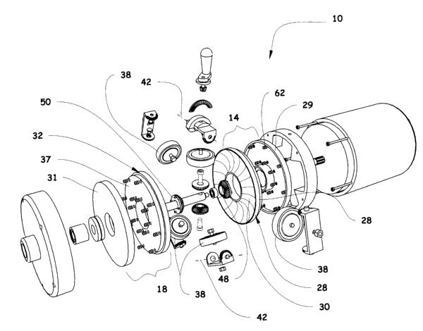
[0027] Figure 2, in an exploded view, illustrates the transmission of Figure
1;
[0028] Figure 3, in a perspective view, illustrates a roller support of the
transmission of Figure 1 supporting traction rollers;
[0029] Figure 4, in a perspective view, illustrates a roller support
supporting
traction rollers in accordance with an alternative embodiment of the present
invention;
[0030] Figure 5a, in perspective partial cross-sectional view, illustrates an
actuator usable in the transmission of Figure 1, the actuator being shown with
an
actuator handle thereof in an unlocked position;
[0031] Figure 5b, in perspective partial cross-sectional view, illustrates the
CA 02618410 2008-02-05
WO 2007/016774 PCT/CA2006/001294
7
actuator of Figure 5a, the actuator handle being shown in a locked position;
[0032] Figure 5c, in perspective partial cross-sectional view, illustrates the
actuator of Figure 5a, the actuator handle being shown in the unlocked
position;
[0033] Figure 5d, in perspective partial cross-sectional view, illustrates the
actuator of Figure 5a, the actuator handle being shown in a brake engaging
position;
[0034] Figure 6, in a perspective cross-sectional view, illustrates a
transmission in accordance with an alternative embodiment of the present
invention;
[0035] Figure 7, in an exploded view, illustrates the transmission of Figure
6;
[0036] Figure 8, in a perspective partial cross-sectional view, illustrates a
roller support of the transmission of Figure 6 supporting traction rollers;
[0037] Figure 9, in a perspective view, illustrates a roller support of the
transmission of Figure 6 supporting traction rollers;
[0038] Figure 10, in a perspective view, illustrates an actuator of the
transmission of Figure 6;
[0039] Figure 11, in a partial perspective view, illustrates the actuator of
the
transmission of Figure 6 with a brake thereof in a released configuration;
[0040] Figure 12, in a partial perspective view, illustrates the actuator of
the
CA 02618410 2008-02-05
WO 2007/016774 PCT/CA2006/001294
8
transmission of Figure 6 with the brake thereof in an engaged configuration;
and
[0041] Figure 13, in a perspective partial cross-sectional view, illustrates a
transmission in accordance with another alternative embodiment of the present
invention.
DETAILED DESCRIPTION
[0042] Referring to Fig. 1, there is shown a transmission 10 for converting an
input rotation in motion having an input angular speed into an output rotation
motion
having an output angular speed. The transmission 10 includes a transmission
body 12.
A first rotating component 14 is rotatably mounted to the transmission body
12. The first
rotating component 14 is rotatable at a first angular speed about a rotation
axis 16.
[0043] A second rotating component 18 is mounted to the transmission body
12 in a substantially parallel and spaced apart relationship relatively to the
first rotating
component 14. The second rotating component 18 is rotatable about the rotation
axis
16 at a second angular speed.
[0044] An output component 20 is mounted to the transmission body 12
substantially concentrically relatively to the first and second rotating
components 14 and
18. The output component 20 is rotatable about the rotation axis 16 at the
output
angular speed.
[0045] A first coupling mechanism 22 is operatively coupied to the first and
second rotating components 14 and 18 such that the rotation of the first
rotating
component 14 causes a rotation of the second rotating component 18. The first
coupling
CA 02618410 2008-02-05
WO 2007/016774 PCT/CA2006/001294
9
mechanism 22 is fixed relatively to the transmission body 12.
[0046] A second coupling mechanism 24 is also provided. The second
coupling mechanism 24 includes a substantially disc-shaped member such as, for
example, a pinion gear 26, mounted to the output component 20 substantially
radially
spaced apart from the rotation axis 16. The substantially disc-shaped member
26 is
disposed between and engaged with the first and second rotating components 14
and
18.
[0047] Rotating the first and second rotating components 14 and 18 produces
a substantially circumferential movement of the disc-shaped member 26
relatively to the
rotation axis 16. In turn, this causes a rotation of the output component 20
relatively to
the transmission body 12.
[0048] The first coupling mechanism 22 is a variable ratio mechanism
allowing to selectively vary a ratio between the first angular speed and the
output speed.
However, in alternative embodiments of the invention, the second coupling
mechanism
or both the first and the second coupling mechanisms are variable ratio
mechanisms
allowing to selectively vary a ratio between the first angular speed and the
output speed.
[0049] In some embodiments of the invention, such as for example in the
embodiments shown in the Figures, the variable ratio mechanism is a
continuously
variable ratio mechanism allowing to continuously vary the ratio between the
output and
input speeds. However, in alternative embodiments of the invention, the
variable ratio
mechanism is a discretely variable mechanism allowing to vary the ratio
between the
output and input speeds in discrete steps.
CA 02618410 2008-02-05
WO 2007/016774 PCT/CA2006/001294
[0050] In some embodiments of the invention, the first rotating component 14
is coupled to a motor 11 through an input shaft 13. Therefore, the first
rotating
component 14 is rotated relatively to the transmission body 12 by the motor
11.
[0051] As better seen in Fig. 2, the first rotating component 14 includes a
first
component toric disc 28. The second rotating component 18 includes a second
rotating
component toric disc 32. The first and second rotating component toric discs
28 and 32
define a substantially annular space 36 therebetween (better seen in Fig. 1).
To that
effect, the first and second rotating component toric discs 28 and 32 each
define
respectively a first and second component grooves 30 and 34, the first and
second
component grooves 30 and 34 being substantially annular and having a
substantially arc
segment shaped cross-section.
[0052] Referring to Fig. 1, the first coupling mechanism 22 includes at least
two motion transmitting traction rollers 38 located in the substantially
annular space 36.
The motion transmitting traction rollers 38 each engage the first and second
rotating
component toric discs 28 and 32.
[0053] As better seen in Fig. 3, a roller support 40 supports the motion
transmitting traction rollers 38. Each of the motion transmitting traction
rollers 38 is
pivotally mounted to the roller support 40 so as to be selectively pivotable
about a
respective roller pivot axis 42, only one of which is shown in Fig. 3. The
roller pivot axes
42 are substantially tangential to and substantially co-planar with the
circumference of a
circle 33 extending substantially parallel to the first and second component
toric discs 28
and 32.
[0054] Each of the traction rollers 38 is further rotatable about a respective
CA 02618410 2008-02-05
WO 2007/016774 PCT/CA2006/001294
11
roller rotation axis 46 substantially perpendicular to the roller pivot axis
42 about which
the traction roller 38 is pivotable. While the transmission 10 includes five
motion
transmitting traction rollers 38, it is within the scope of the invention to
have a
transmission having any other suitable number of motion transmitting traction
rollers 38.
[0055] Returning to Fig. 1, the first rotating component 14 includes a
substantially annular first component face gear 48. The first component face
gear 48 is
substantially concentric relatively to the output component 20 and located
radially
inwardly relatively to the first component groove 30 and the motion
transmitting traction
rollers 38. The first component face gear 48 is operatively coupled to the
first toric disc
28 such that the first component face gear 48 and the first toric disc 28
rotate jointly at
the first angular speed.
[0056] The second rotating component 18 includes a substantially annular
second component face gear 50. The second component face gear 50 is
substantially
concentric relatively to the output component 20 and located radially inwardly
relatively
to the second component groove 34 and the motion transmitting traction rollers
38. The
second component face gear 50 is operatively coupled to the first toric disc
28 such that
the second component face gear 50 and the second toric disc 32 rotate jointly
at the first
angular speed.
[0057] The first and second component face gears 48, 50 face each other
and the pinion gear 26 engages both the first and second component face gears
48, 50.
It should be noted that while the output member 20 extends through the second
component face gear 50, all the second rotating component 18, including the
second
component face gear 50, is rotatable relatively to the output member 20.
CA 02618410 2008-02-05
WO 2007/016774 PCT/CA2006/001294
12
[0058] Referring to Fig. 1, the pinion gear 26 is mounted to a pinion shaft
52.
The pinion shaft 52 is operatively coupled to the output component 20 so that
a
substantially circumferential movement of the pinion gear 26 causes a rotation
of the
output component 20.
[0059] The transmission 10 shown in Figs. 1 and 2 includes two pinion gears
26 each mounted to a respective pinion shaft 52. Each of the pinion shafts 52
is
operatively coupled to the output component 20 so that a substantially
circumferential
movement of the pinion gears 26 causes a rotation of the output component 20.
In
alternative embodiments of the invention, a transmission similar to the
transmission 10
includes any other suitable number of pinion gears.
[0060] The transmission 10 has been described generally hereinabove.
Hereinbelow, a more detailed description of some components of the
transmission 10 is
found.
[0061] Referring to Fig. 1, in some embodiments of the invention, a biasing
component 62 is operatively coupled to the transmission body 12 and to the
first and
second component toric discs 28 and 32 for biasing the first and second
component toric
discs 28 and 32 towards each other. For example, the biasing component 62
includes
springs biasing the first and second component toric discs 28 and 32 towards
each
other.
[0062] The transmission body 12 includes a transmission body first section 64
and a transmission body second section 66. The transmission body first and
second
sections 64, 66 are each substantially cylindrical and include respectively a
transmission
body first end wall and a transmission body second end wall 65, 67. A support
body 57
CA 02618410 2008-02-05
WO 2007/016774 PCT/CA2006/001294
13
of the roller support 40 is inserted between the transmission body first and
second
sections 64 and 66. The transmission body first section 64, the transmission
body
second section 66 and the support body 57 are secured to each other so as to
form an
enclosure using transmission body fasteners 68. For example, the transmission
body
fasteners 68 include a nut and a bolt, thereby allowing to access the interior
of the
transmission 10 for maintenance, repairs or other purposes relatively easily.
[0063] Referring to Fig. 2, in some embodiments of the invention, the first
and
second component toric discs 28 and 32 respectively include a first toric disc
base 29
and a second toric disc base 31. The first and second toric disc bases 29 and
31 are
rotatably mounted inside the transmission body 12 and each receive
respectively a first
and a second toric component 35 and 37. The first and second toric components
35
and 37 are mounted facing each other between the first and second component
toric
disc bases 29 and 33. The springs forming the biasing element 62 are provided
between the first component toric disc base 29 and the first toric component
35 and
between the second component toric disc base 31 and the second toric component
35.
However, in alternative embodiments of the invention, the first and second
component
toric discs 28 and 32 may take any other suitable configuration.
[0064] The output component 20 includes an output shaft 54 extending
through the second rotating component 18. The output shaft 54 includes a
pinion
coupling portion 56 located between the first and second component toric discs
28 and
32. The pinion shafts 52 are mechanically coupled to the pinion coupling
portion 56.
[0065] Referring to Fig. 3, the roller support 40 includes a substantially
annular support body 57 and at least two roller holders 59, each receiving a
respective
motion transmitting traction roller 38. Each of the roller holders 59 is
pivotally mounted
CA 02618410 2008-02-05
WO 2007/016774 PCT/CA2006/001294
14
to the support body 57 so as to be selectively pivotable about a respective
one of the
roller pivot axes 42. In some embodiments of the invention, the roller holders
59 are
operatively coupled to each other so as to be jointly pivotable about their
respective
roller pivot axes 42.
[0066] The transmission 10 includes an actuator 58 operatively coupled to the
roller holders 59 for selectively pivoting the roller holders 59 about their
respective roller
pivot axes 42. The actuator 58 includes an actuator axle 72 to which is
mounted an
actuator gear 74. The actuator gear 74 is rotatable about an actuator rotation
axle 73
extending substantially radially outwardly using an actuator handle 70 that is
mounted
eccentrically relatively to the actuator axle 72 through a handle mounting
component 71.
The actuator axle 72 extends through the roller support 40 and the actuator
gear 74 is
located substantially adjacent the roller holder 59, as described in further
details
hereinbelow.
[0067] The support body 57 defines roller holder receiving recesses 76. Each
of the roller holder receiving recesses 76 receives a respective roller holder
59. For
example, each roller holder 59 includes a roller holder base 78 and two roller
holder
arms 80 extending substantially perpendicularly therefrom in a spaced apart
relationship
relatively to each other. Therefore the roller holders 59 are substantially U-
shaped.
[0068] Each of the roller holder arm 80 defines an arm first end 82 located
substantially adjacent the roller holder base 78 and an opposed arm second end
84
located distally relatively to the roller holder base 78. The arm second ends
84 are
substantially arc segment shaped.
[0069] Arm teeth 86 are provided substantially adjacent the arm second ends
CA 02618410 2008-02-05
WO 2007/016774 PCT/CA2006/001294
84. The roller holders 59 and the support body 57 are configured and sized so
that the
arm teeth 86 of adjacent roller holders 54 engage each other. Therefore,
pivoting one of
the roller holders 59 causes the other roller holders to pivot substantially
similarly. The
reader skilled in the art will readily appreciate that the roller holders 59
may be
operatively coupled to each other so that pivoting one of the roller holders
59 causes the
other roller holders 59 to pivot in any other suitable manner.
[0070] A traction roller axle 88 is affixed to each of the roller holder bases
78
and extends substantially radially inwardly therefrom. The traction holder
axles 88 each
rotatably receive one of the motion transmitting traction rollers 38 so that
the motion
transmitting traction rollers 38 are substantially parallel to the roller
holder base 78.
[0071] One the roller holders 59' located substantially adjacent the actuator
gear 74 includes a roller holder gear 88. The roller holder gear 88 is
substantially
annular and extends substantially perpendicularly to the actuator gear 74 and
to the
circle 33. The roller holder gear 88 engages the actuator gear 74 so that a
rotation of the
actuator gear 74 results in the roller holders 59 pivoting about their
respective roller pivot
axis 42.
[0072] In some embodiments of the invention, for example in the embodiment
shown in Fig. 4 and described in further details hereinbelow, the actuator 58
includes a
lock. The lock is operable between a locked configuration and an unlocked
configuration. In the locked configuration, the lock prevents the roller
holders 59 from
rotating about their respective holder pivot axes 42. In the unlocked
configuration, the
lock allows the rotation of the roller holders 59 about their respective
holder pivot axes
42.
CA 02618410 2008-02-05
WO 2007/016774 PCT/CA2006/001294
16
[0073] In some embodiments of the invention, the actuator 58 includes a
brake 60 operable between an engaged configuration and a released
configuration. The
brake 60 is operatively coupled to the pinion gear 26 for preventing a
rotation of the
pinion gear 26 when the brake 60 is in the engaged configuration. When the
brake 60 is
in the released configuration, a rotation of the pinion gear 26 is allowed.
[0074] Fig. 4 illustrates an alternative embodiment of the invention wherein
the roller holders 59' are coupled to each other so as to be jointly rotatable
about their
respective roller pivot axes 42 in an alternative manner. Instead of having
arm teeth 86
formed at the end of roller holder arms, the roller holders 59' shown in Fig.
4 each
include a respective roller holder coupling member 90 located substantially
opposed to
the roller holder base 78 relatively to the traction rollers 38. Alternative
roller holder
arms 80' which do not include teeth extend from the roller holder base 78
similarly to the
roller holder arms 80.
[0075] Each of the roller holder coupling member 90 is secured to the
traction roller axle 88 and includes a holder coupling member base 92
substantially
parallel to the roller holder base 78. Two holder coupling member arms 94
extend
substantially outwardly respectively from both ends of each holder coupling
member
base 92. Each of the coupling member arms 94 includes a coupling member arm
first
end 96 located substantially adjacent the holder coupling member base 92 and a
coupling arm second end 98 located distally relatively to the holder coupling
member 92.
[0076] Coupling arm teeth 100 and form substantially into each coupling
member arms 94 substantially adjacent the coupling arm second ends 98. The
coupling
arm teeth 100 of adjacent roller holders 59' engage each other so that
pivoting one of
the roller holders 59' relatively to its respective roller pivot axis 42
results in all the roller
CA 02618410 2008-02-05
WO 2007/016774 PCT/CA2006/001294
17
holders 59' pivoting jointly about their respective holder pivot axes 42 by
substantially
the same angle.
[0077] Also, as shown in Fig. 4, in some embodiments of the invention, the
pinion gears 26 are supported by a pinion support 102. Pinion support 102 is
substantially annular and defines a pinion support passageway 104 extending
substantially longitudinally therethrough. The pinion gears 26 and the pinion
shafts 52
are supported within the pinion support passageway 104.
[0078] The pinion support 102 further defines a pinion support circumferential
surface 107. The pinion support circumferential surface 107 includes pinion
support
grooves 111 extending substantially longitudinally and transversely radially
thereinto. In
other words, the pinion support grooves 111 extend helicoidally relatively to
the
longitudinal axis 16. The pinion support grooves 111 are usable for stopping a
rotation of
the pinion gears 26 relatively to the support body 12, thereby providing a
brake for
preventing the output member 20 from rotating. The pinion support grooves 111
extend
substantially obliquely onto the pinion support circumferential surface 107
relatively to
the longitudinal axis 16 of the transmission 10.
[0079] Fig. 4 also illustrates an alternative actuator 58'. The actuator 58'
is
similar to the actuator 58 except that it includes an actuator lock and
actuates the brake
60. To that effect, as better seen in Fig. 5a, the actuator 58' includes the
actuator gear
74 and the actuator axle 72. The actuator axle 72 extends through an actuator
base
105, which is securable to the transmission body 12, and is coupled to an
actuator body
106 including an actuator handle 109 mounted eccentrically relatively to the
actuator
axle 72. An actuator body 106 is located opposite the actuator gear 74
relatively to the
actuator axle 72. The actuator axle 72 is operatively coupled to the actuator
handle 109
CA 02618410 2008-02-05
WO 2007/016774 PCT/CA2006/001294
18
such that rotating the actuator handle 109 about the actuator axle 72 rotates
the
actuator gear 74.
[0080] In opposition to the actuator 58, the actuator handle 109 is not fixed
relatively to the actuator body 106 but is mounted so as to be pivotable about
an axis
substantially perpendicular to the rotation axis of the actuator gear 72 in a
plane
substantially perpendicular to the actuator body 106 passing through the
actuator axle.
[0081] To that effect, referring to Fig. 5a, the actuator body 106 includes an
actuator body handle support such as, for example, a fork including two
support arms
201, only one of which is seen in Fig. 5a. The support arms 201 are
substantially
parallel to each other and in a spaced apart relationship relatively to each
other.
[0082] The handle 109 and a brake engaging member 203 are mounted to
the support arms 201. The brake engaging member 203 is substantially elongated
and
defines a substantially elongated engaging member-to-handle coupling aperture
205.
The brake engaging member 203 defines an engaging member first end 207 and a
substantially longitudinally opposed engaging member second end 209. The brake
engaging member 203 is pivotally mounted to the support arms 201 substantially
adjacent the engaging member first end 207 so as to be pivotable in a plane
substantially parallel to a plane in which the handle 109 is pivotable. The
engaging
member-to-handle coupling aperture 205 is substantially longitudinally
elongated.
[0083] A handle support axle 120 extends between the support arms 201. A
handle support cylinder 122 is mounted substantially eccentrically to the
handle support
axle 120. The handle support cylinder 122 extends through the engaging member-
to-
handle coupling aperture 205. The handle support axle 120 is operatively
coupled to the
CA 02618410 2008-02-05
WO 2007/016774 PCT/CA2006/001294
19
actuator handle 198 such that a rotation of the actuator handle 109 results in
the handle
support cylinder 122 rotating within the engaging member-to-handle coupling
aperture
205.
[0084] The brake engaging member 203 allows to lock the actuator handle
109 so as to prevent a rotation of the roller holders 59 relatively to their
respective roller
pivot axes 46.
[0085] In some embodiments of the invention, a brake rod 124 extends
substantially radially into the transmission body 12. The brake rod 124
extends through
the roller holder 59' located substantially in register with the actuator 58'
so as to be
substantially radially movable relatively thereto. The brake rod 124 is
coupled to a
biasing element 126 biasing the brake rod 124 substantially away from the
pinion
support grooves 104. A brake actuating component 128 is operatively coupled to
the
biasing element 126 for selectively moving at least a portion of the brake
biasing
element 126 towards the pinion gears 26 so as to move brake rod 124 into one
of the
pinion support grooves 111.
[0086] In this configuration, called the engaged configuration, the brake rod
124 engages the pinion support grooves 111 so as to prevent the pinion support
102
from rotating. For example, this movement of the brake biasing element 126 is
provided
through the brake actuating component 128 operatively coupled to the actuator
handle
109 such that pivoting the actuator handle 109 towards the brake actuating
component
128 causes the brake rod 124 to be biased towards the pinion support 102.
[0087] The actuator handle 109 is movable between a locked position, shown
in Fig. 5b, an unlocked position, shown in Figs 5a and 5c, and a brake
actuating position
CA 02618410 2008-02-05
WO 2007/016774 PCT/CA2006/001294
shown in Fig 5d. In the locked position, the handle 109 extends substantially
towards the
actuator axle 72 and biases the engaging member second end 209 towards the
actuator
base 105 as the cylinder 122 rotates within the aperture 120. The brake
engaging
member 203 then frictionally engages the actuator base 105 and therefore locks
the
actuator handle 109 so that the actuator gear 74 does not rotate.
[0088] In the unlocked position, the brake engaging member 203 is spaced
apart from the actuator base 105 and the handle extends substantially radially
outwardly. In this position, the brake rod 124 is spaced apart from the pinion
support
grooves 104 which, therefore, allows the pinion support 108 to rotate about
the rotation
axis 16 in response to the pinion gears 26 rotating relative to the first and
second face
gears. The brake 60 is therefore in the released configuration.
[0089] In the brake actuating position, the actuator handle 109 extends
substantially away from the actuator axle 72 and moves the brake actuating
component
128 so as to bias the brake rod 124 towards the pinion support 102 so that the
brake 60
achieves an engaged configuration. If the brake rod 124 is not aligned with
one of the
pinion support groove 108, any slight motion of the pinion support 102 caused
by small
deviation from an exact parallel configuration of the traction rollers 59 will
cause the
pinion support 102 to rotate such that one of the pinion support grooves 111
is
substantially in register with the brake rod 124. The brake rod 124 will,
therefore, be
able to engage the pinion support groove 108.
[0090] It should be noted that the pinion support grooves 111 are oriented
such that a rotation of the pinion support 102 in a given direction will cause
an opposite
effect on the traction rollers resulting in a compensation of this movement of
the pinion
support 102. Then, relatively small mechanical constraints are present in the
actuator
CA 02618410 2008-02-05
WO 2007/016774 PCT/CA2006/001294
21
brake 60 and the pinion support 102.
[0091] In use, the motor 12 rotates the first rotating component 14 at a first
angular speed. This causes the first component toric disc 28 and the first
component
face gear 48 to both rotate at the first angular speed. This rotational motion
is
transmitted to the second rotating component 18 through the motion
transmitting traction
rollers 38, which causes the second rotating component 18 to rotate at the
second
angular speed. This causes the second component face gear 50 and the second
component toric disc 32 rotate at the second angular speed. The movement of
the
second coupling mechanism 24 and of the output component 20 depends on the
orientation of the motion transmitting traction rollers 38.
[0092] When the motion transmitting traction rollers 38 are such that they
engage the first and second component toric discs 28 and 32 at a substantially
similar
radial distance from the rotation axis 16, the first and second component face
gears 48
and 50 rotate at the same absolute angular speed but in opposite directions.
This
causes the pinion gears 26 to rotate about the pinion shafts 52 but to remain
circumferentially fixed relatively to the transmission body 12. Therefore, in
this
configuration, shown in Fig. 1, the output member 20 is not rotating.
[0093] If the motion transmitting traction rollers 38 are pivoted about their
roller pivot axes using the actuator 58, 58', the output component will rotate
either in the
same direction as the input shaft 13 or in an opposite direction to the input
shaft 13,
depending on the orientation of the motion transmitting traction rollers 38.
[0094] First, the situation in which the motion transmitting traction rollers
38
are pivoted such that a radial distance between the rotation axis 16 and the
contact
CA 02618410 2008-02-05
WO 2007/016774 PCT/CA2006/001294
22
point between the motion transmitting traction rollers 38 and the first
component toric
disc 28 is smaller than a radial distance between the rotation axis 16 and the
motion
transmitting traction rollers 38 at a location at which they contact the
second component
toric disc 32 is considered. In this case, when the motion transmitting
traction rollers 38
rotate 360 degrees about their respective roller rotation axes 46, the first
rotating
component 14 rotates over a larger angle than the second rotating component 18
since
the motion transmitting traction rollers 38 are circumferentially fixed
relatively to the
transmission body 12. Also, the first rotating component 14 rotates in a
direction
opposite to a direction in which the second rotating component 18 rotates.
[0095] Therefore, the second face gear 50 will rotate in a direction opposed
to
the rotation of the first face gear 48 at a lower angular speed than the first
face gear 50.
In turn, the pinion gears 26 have a circumferential motion in the same
direction as the
input shaft 13. Finally, this will cause the output member 20 to rotate in the
same
direction as the input shaft 13, but at a lower anguiar speed.
[0096] In the opposite case, the second component face gear 50 is rotated
with in the same direction as the first component face gear 48 and at an
absolute
angular speed that is larger than the angular speed of the first component
face gear 48,
which will result in the circumferential motion of the pinion gears 26 to be
in opposite
direction to the rotational direction of the input shaft 13, which will
therefore cause the
output component 20 to rotate in opposite direction to the input shaft 13.
[0097] Therefore, the transmission 10 allows to selectively rotate the output
member 20 in the same direction as the input shaft 13, rotate the output
member 20 in
opposite direction to the input shaft 13 or to stop the rotation of the output
member 20.
CA 02618410 2008-02-05
WO 2007/016774 PCT/CA2006/001294
23
[0098] Pivoting the motion transmitting traction rollers 38 about the roller
pivot
axes 42 is performed by moving the actuator handle 109 so as to cause the
actuator
gear 74 to rotate. As the actuator gear 74 rotates, it moves the roller
holders 59, 59'
with which it is engaged. In turn, this causes all the roller holders 59, 59'
to pivot to
substantially the same angle.
[0099] The transmission 10 therefore allows to couple the motor 11 to the
output member 20 to allow the output member to rotate in two directions and to
be stably
stopped while the motor 11 is powered at a substantially constant speed. Of
course, the
motor may also be operated at a variabie speed without departing from the
scope of the
invention. Also, a ratio between the input speed and the output speed is
continuousiy
variable. Furthermore, in the transmission 10, the maximal speed of rotation
of the
output member 20 in one specific direction is larger than the maximal speed of
rotation
of the output member 20 in a direction opposed to one specific direction for a
predetermined input speed. This is desireable in many applications, for
example for
vehicles which are typically operated at faster speed when going in a forward
going
direction than when going in a rearward direction.
[0100] Figs. 6 and 7 illustrate an alternative transmission 10a. The
transmission 10a differs from the transmission 10 in that it is the second
coupling
mechanism 24a that is a variable ratio mechanism allowing to selectively vary
a ratio
between the first angular speed and the output angular speed.
[0101] To that effect, the transmission 10a includes a first rotating
component
14a, the first rotating component 14a including a first component toric disc
28a. Also,
the transmission 10a includes a second rotating component 18a, the second
rotating
component 18a including a second rotating component toric disc 32a. The first
and
CA 02618410 2008-02-05
WO 2007/016774 PCT/CA2006/001294
24
second rotating component toric discs 28a and 32a define a substantially
annular space
36a therebetween. The first and second component toric discs 28a and 32a are
substantially similar to the first and second component toric discs 28 and 32
of the
transmission 10 shown in Figs. 1 through 5D. Therefore, the first and second
component toric discs 28a and 32a will not be described in further details.
[0102] The second coupling mechanism 24a includes at least two motion
transmitting traction rollers 38a located in the substantially annular space
36a. The
motion transmitting traction rollers 38a each engage the first and second
rotating
component toric discs 28a and 32a.
[0103] Referring to Fig. 8, a roller support 40a supports each of the motion
transmitting traction rollers 38a. Each of the motion transmitting traction
rollers 38a is
pivotally mounted to the roller support 40a so as to be selectively pivotable
about a
respective roller pivot axis 42a. The roller pivot axis 42a is substantially
tangential to
and substantially co-planar with the circumference of a circle 33a extending
substantially
parallel to the first and second rotating component toric discs 28a and 32a.
Each of the
traction rollers 38a is further rotatable about a respective roller rotation
axis 46a, each
roller rotation axis 46a being substantially perpendicular to a respective one
of the roller
pivot axes 42a.
[0104] The roller supports 40a are movable substantially circumferentially
relatively around the transmission rotation axis 16 relatively to the
transmission body
12a. The roller supports 40a are operatively coupled to an output component
20a so
that the substantially circumferential movement of the motion transmitting
traction rollers
38a causes a rotation of the output component 20a.
CA 02618410 2008-02-05
WO 2007/016774 PCT/CA2006/001294
[0105] As better seen in Fig. 7, the first rotating component 14a includes a
substantially annular first component gear 48a. The first component gear 48a
is
substantially concentric relatively to the output component 20a. The first
component
gear 48a is located radially outwardly relatively to the motion transmitting
traction rollers
38a.
[0106] The second rotating component 18a includes a substantially annular
second component gear 50a. The second component gear 50a is substantially
concentric relatively to the output component 20a. The second component gear
50a is
located radially outwardly relatively to the motion transmitting traction
rollers 38a.
[0107] A first coupling mechanism 22a, seen in Figs 6, engages the first and
second component gears 48a and 50a so that the rotation of the first rotating
component
48a causes a rotation of a second component 48a. For example, the first
coupling
mechanism 28a includes a pinion gear 26a engaging both first and second
component
gears 48a and 50a.
[0108] In some embodiments of the invention, the first coupling mechanism
22a includes at least two pinion gears 26a each engaging both said first and
second
component gears 48a and 50a. One of the at least two pinion gears 26a is
usable for
tapping an output rotational motion. The other one of the at least two pinion
gears 26a
is rotatable by a power input. When the two pinion gears 26a have
substantially the
same number of teeth, the two pinion gears 26a rotate at the same angular
speed.
Therefore, the pinion gear 26a usable for tapping an output rotational motion
effectively
taps into a rotational motion having the same rotation speed as the other
pinion gear
through which power is input into the transmission 10a.
CA 02618410 2008-02-05
WO 2007/016774 PCT/CA2006/001294
26
[0109] However, in alternative embodiments of the invention, power is input
into the transmission 10a in any other suitable manner. For example, it is
within the
scope of the invention to rotate the first input component 14a relatively to
the
transmission body 12a using a motor, similarly to the embodiment of the
invention
shown in Fig. 1.
[0110] In other embodiments of the invention, for example in the transmission
10b shown in Fig. 13, the first coupling mechanism 22b includes a coupling
mechanism
input 138 for receiving an input rotational motion and two output gears 132
and 134
each engaging a respective one of a first and a second component gears 48b and
50b.
The first coupling mechanism 22b is configured such that the first and second
output
gears 132 and 134 rotate first and second component gears 48b and 50b such
that the
first and second rotation speeds differ from each other. This may be achieved,
for
example, using a gear train 136 interposed between the coupling mechanism
input 138
and the two output gears 132 and 134.
[0111] As better seen in Fig. 8, the roller support 40a includes a
substantially
annular support body 141. The roller support 40a includes at least two roller
holders
59a each receiving a respective motion transmitting traction roller 38a. Each
of the roller
holders 59a is pivotally mounted to the support body 141 so as to be
selectively
pivotable about a respective one of the roller pivot axes 42a. The roller
holders 59a are
operatively coupled to each other so as to be jointly pivotable about their
respective
roller pivot axes 42a.
[0112] As seen in Fig. 10, an actuator 58a is operatively coupled to the
roller
holders 59a for selectively pivoting the roller holders 58a about their
respective roller
pivot axes 42a. The actuator 58a is described in further details hereinbelow.
CA 02618410 2008-02-05
WO 2007/016774 PCT/CA2006/001294
27
[0113] In some embodiments of the invention, the actuator 58a includes a
brake 60a, operable between an engaged configuration, seen in Fig. 12, and a
released
configuration, seen in Fig. 11.
[0114] The brake 60a is operatively coupled to the roller supports 59a for
preventing a substantially circumferential movement of the motion transmitting
traction
rollers 38a when the brake 60a is in the engaged configuration. When the brake
60a is
in the released configuration, the substantially circumferential movement of
the motion
transmitting traction rollers 38a is allowed.
[0115] Referring to Fig. 6, in some embodiments of the invention, the second
coupling mechanism 24a includes at least two output pinions 140. Each of the
output
pinions 140 is rotatable about a respective output pinion rotation axis 142
extending
substantially radially. The output pinions 140 are located between the first
and second
rotating components 14a and 18a. The output pinions 140 are operatively
coupled to
the motion transmitting traction rollers 38a so that upon the traction rollers
38a moving
circumferentially relatively to the transmission body 12a, the output pinions
140 rotate
circumferentially relatively to the transmission body 12a.
[0116] The output component 20a includes two output shafts 143 rotatably
mounted to the transmission body 12a. The output shafts 143 are operatively
coupled to
the output pinions 140 so that a circumferential movement of the output
pinions 140
causes the output shafts 143 to differentially rotate relative to the
transmission body. In
other words, the output pinions 140 and the output shafts 143 form a
differential having
a power input at the output pinions 140.
[0117] To that effect, each of the output shafts 143 extends through a
CA 02618410 2008-02-05
WO 2007/016774 PCT/CA2006/001294
28
respective one of the first and second rotating components 14a and 18a. Each
of the
output shafts 143 supports an output shafts gear 144 located at one end
thereof. The
output shaft gears 144 each engage the output pinions 140. Each of the output
shafts
143 is independently rotatable relatively to the transmission body 12a and
relatively to
the first and second rotating components 14a and 18a.
[0118] The transmission 10a has been described generally hereinabove.
Hereinbelow, a non-limiting specific embodiment of the transmission 10a is
described in
further details. The reader skilled in the art will readily appreciate that
many of the
details described hereinbelow may be implemented in many alternative manners
without
departing from the scope of the present invention as defined in the appended
claims.
[0119] Fig. 8 shows the support body 141 and the support holders 59a. The
support body 141 includes a support body fixed member 146 from which support
body
pins 147 extend substantially radially outwardly. The support body fixed
member 146 is
fixed as it does no rotate circumferentially freely about the transmission
rotation axis 16.
The support body 141 further includes a support body rotatable element 148
mounted to
the support body fixed member 146 so as to be rotatable about the transmission
rotation
axis 16.
[0120] The roller holders 59a are secured to the support body 141. The roller
holders include a roller holder body 150 for receiving the motion transmitting
traction
rollers 38a. The roller holders bodies 150 are each mechanically coupled to a
roller
holder shaft 152 extending substantially radially inwardly towards the
rotation axis 16a.
The roller holder shafts 152 are all mechanically coupled to a support central
member
154. Each of the roller holder shafts 152 supports a respective one of the
output
pinions. The output pinions 140 are mounted to the roller holder shafts so as
to be
CA 02618410 2008-02-05
WO 2007/016774 PCT/CA2006/001294
29
rotatable freely about their respective output pinions rotation axes 142.
[0121] Each of the roller supports 59a includes a roller pivotable component
166 pivotally mounted to the support body rotatable element 148 so as to be
pivotable in
a substantially longitudinally and radially extending plane. Roller support-to-
roller body
connecting components 155 interconnect the motion transmitting traction
rollers 38a to
the roller body 140.
[0122] To that effect, each of the roller pivotable component 166 includes two
connecting component radial members 162 extending substantially radially
inwardly
from a respective connecting component circumferential member 160. The
connecting
component circumferential member 160 is coupled to the support body 141 so as
to be
rotatable about an axis extending substantially tangentially to the
circumference of the
support body 141. The connecting component radial members 162 each engage a
respective roller support-to-roller body connecting components 155 so as to be
slidable
relatively thereto. To that effect, each of roller support-to-roller body
connecting
components 155 defines two roller body passageways 157 extending substantially
radially relatively thereto.
[0123] Referring to Fig. 9, the support body 141 is supported by a
substantially annular support outer member 164. The support outer member 164
defines support outer member grooves 169 extending substantially helicoidally
respectively to the transmission body 12a. In other words, the support outer
member
grooves 169 extend substantially longitudinally and substantially
circumferentially
relatively to the transmission body 12a. The support outer member grooves 169
each
receive a respective one of the support body pins 147.
CA 02618410 2008-02-05
WO 2007/016774 PCT/CA2006/001294
[0124] Body guiding grooves 171 are provided into the transmission body 12a
substantially in register with each support body pin 147 and extend
substantially radially
outwardly from the transmission body inner surface towards the transmission
body outer
surface. The body guiding grooves extend substantially longitudinally and
therefore
restrain a movement of the support body pins 147 in the longitudinal
direction. Also, as
shown in Fig. 10, a worm gear 170 extends substantially circumferentially onto
the
support outer member 164.
[0125] Referring to Fig. 11, the actuator 58a includes an actuator motor 172
such as, for example, an actuator electrical motor that is controllable using
a
conventional controller. The actuator motor 172 is coupled to at least one
actuator
output groove 174 engaging the worm gear 170. The actuator output groove 174
and
the worm gear 170 are substantially parallel relatively to each other.
Therefore, rotating
the actuator output groove 174 results in the worm gear 172 to move
substantially
circumferentially relatively to the actuator motor 172.
[0126] In some embodiments of the invention, the actuator 58a includes a
brake 60a. The brake 60a is operable between the engaged configuration and the
released configuration. Referring to Fig 11, wherein the brake 60a is shown in
the
released configuration, the brake 60a includes a brake mobile member 181
slidably
mounted onto a brake body 183. Electrical contacts 182a and 182b extend from
the
brake body 183 circumferentially spaced apart from each other. The brake
mobile
member 181 is mounted so as to be slidable between the electrical contacts
182a and
182b.
[0127] The brake body 183 is pivotally mounted to the transmission body 12a
so as to be mobile between a mobile member disengaged position and a mobile
CA 02618410 2008-02-05
WO 2007/016774 PCT/CA2006/001294
31
member engaged position. In the mobile member disengaged position, the brake
mobile
member 181 is uncoupled from the support body 141 and the brake 60a is in the
released configuration, as seen in Fig. 11. In the brake engaged
configuration, the
brake mobile member 181 extends through brake grooves 180 formed into the
support
body outer member 174 and engages the support body 141, as shown in Fig. 12.
The
brake mobile member 181 frictionally engages the support body 141 so as to
move
relatively to the brake grooves 180 when the motion transmitting traction
rollers 38a
move circumferentialiy relatively to the transmission body 12.
[0128] The electrical contacts 182a and 182b are operatively coupled to the
actuator motor 172 so as to cause the motion transmitting traction rollers 38a
to be
pivoted about their holders pivot axes 42a in a direction leading the motion
transmitting
traction rollers 38a to move in a direction opposite to the direction in which
the brake
mobile member 181 has moved to reach one of the respective one of the
electrical
contacts 182a and 182b. Therefore, the electrical contacts 182a and 182b cause
a
movement opposite to any perturbation that may occur to the support body 141.
It
should be noted that the brake 60a may only be in the engaged configuration
when the
traction rollers 38a are such that they engage the first and second rotating
components
14a and 18a at a substantially similar radial distance from the transmission
rotation axis
16a. Indeed, it is only in this configuration that the traction rollers 38a do
not move
circumferentially relatively to the transmission body 12a and in which the
brake 60a is
required.
[0129] In use, pivoting the motion transmitting traction rollers 38a
relatively to
the holder pivot axis 42a causes the motion transmitting traction rollers 38a
to engage
the first and second rotating components 14a and 18a at different radial
distances. This
causes the motion transmitting traction rollers 38a to move circumferentially
relatively to
the transmission body 12a, similarly to the way in which the pinion gears 26
move
CA 02618410 2008-02-05
WO 2007/016774 PCT/CA2006/001294
32
circumferentially relatively to the first and second rotating components 14
and 18 in the
transmission 10.
[0130] It should be noted that in the transmission 10a, the rotational angular
speed of the first and second rotating components is fixed and that it is by
varying the
inclination of the motion transmitting traction rollers 38a that the
rotational speed of the
output shafts 142 is changed. The output shafts 142 are mounted in a
differential
arrangement such that the average of the rotation speed of the two output
shafts 142 is
equal to the speed to which the motion transmitting traction rollers 38a move
circumferentially relatively to the transmission body 12a.
[0131] As seen from Fig. 11, when the actuator motor 172 is actuated, the
support outer member 164 moves substantially circumferentially. In turn, this
causes the
support body pins 147 to move substantially circumferentially and therefore to
move
substantially longitudinally as they are constrained to move within the
support outer
member grooves 169. Therefore, this causes the support body 141 to move
substantially longitudinally which, in turn, causes the motion transmitting
traction rollers
38a to pivot about the roller supports pivot axes.
[0132] The reader skilled in the art will readily appreciate that components
that are rotatably mounted relatively to other components may be mounted
relatively to
each other in any suitable manner such as, for example, using bearing or
bushings.
[0133] Although the present invention has been described hereinabove by
way of preferred embodiments thereof, it can be modified, without departing
from the
spirit and nature of the subject invention as defined in the appended claims.