Note: Descriptions are shown in the official language in which they were submitted.
CA 02618437 2008-02-07
WO 2007/020637 PCT/IL2006/000946
1
UNIVERSAL ELECTRONIC IMMOBILIZING FOR A VEHICLE
FIELD OF THE TNVENTION
The present invention relates generally to systems that prevent vehicle theft
and, more particularly, to systems that wirelessly disable one or more vehicle-
enabling
components and to universal electronic Immobilizing for a vehicle.
BACKGROUND OF THE INVENTION
Mechanical veliicular locking devices that lock a manually operated vehicle
component provide some fonn of physical impediment to the normal operation of
the
vehicle.
The mechanical steering-wheel locking crosspiece, for example, comprises a
lockable crosspiece that is manually biased and locked against a vehicle
steering
wheel. One en.d of the crosspiece typically extends outward of the steering
wheel so
that upon rotation, the end contacts a surface associated with the vehicle
passenger
cabin, thereby preventing full rotation of the steering wheel.
Other locking crosspieces tliat bias and lock against manualiy operated
veiZicle
components include, inter a1ia, crosspieces that bias against a gearshift and
a
handbrake lever.
The locking crosspiece is simple to use, can be implemented on a wide variety
of vehicle brands, can be purchased off-the-shelf and deployed without
intervention of
a vehicle mechanic. Additionally, the locking crosspiece is easily spotted
tlirough the
vehicle windoNvs, thereby acting as a visual detelTent to a would-be vehicle
thief.
Electronic in-anobilizers that are not visible, for example, may not provide a
deterrent
until the thief has already entered the vehicle; often following damage to the
vehicle
door locks and/or windows.
The locking crosspiece, however, has a significant drawback in that it is
typically uiilocked using a simple key, making the vehicle an easy theft
target by an
experienced thief with a lock-pick.
Further, the locking crosspiece is a stand-alone device that the operator may
choose to deploy without activating a secondary device, for example a device
that
electronically disables an electronic vehicle-enabling component, for example
a
barlcing system, a fuel punip or total vehicle ininobilizer. Without such
secondary
CA 02618437 2008-02-07
WO 2007/020637 PCT/IL2006/000946
2
activation, the vehicle becomes an easy and tempting target to a would-be
vehicle
thief.
Additionally, the locking crosspiece requires a separate key to lock and
unlock. Finding the crosspiece key in a purse, pocket or on a ring of keys can
be a
nuisance that may deter the vehicle operator from using the steering wlieel
crosspiece
lock altogether. In general it is unusual for users to be prepared to use both
an
immobilizer and a physical lock together. Those who have an immobilizer do not
make use of an additional physical lock because of the additional bother.
SUMMARY OF THE INVENTION
Some embodiments of the present invention successfully address at least soine
of the shortcomings of the prior art by providing a vehicle security system
for
securing a vehicle against theft, the system comprising, a driving function
disablemeilt coniponent configured to bias against a moveable vehicle
component,
thereby to disable a driving function when biased, a remotely operable
transducer
configured to maintain or release biasing in the driving fiinction
disablen7ent
component, atid a wireless handheld transceiver conf'igured to transn-iit a
wireless
drive-activating signal to operate the transducer.
In einbodiments, the transducer includes a locking mechanism for locking the
driving fiinction disablement component in the biased position. In
embodiments, the
moveable vehicle component is any one of the group consisting of a steering
wheel, a
tire, a clutch, a gearshift, an accelerator pedal, a hand brake lever, and a
brake pedal.
In enibodiments, the system further comprises an inunobilizer and the wireless
handheld transceiver is fiirther configured to operate the immobilizer. In
embodiments, the immobilizer comprises an electronic vehicle component-
inunobilizing relay.
In embodiments, the electronic vehicle component is any one of the group
consisting of, a motor ignition, a fuel pump, a fuel injector, a gearshift, a
total vehicle
imunobilizer, and a. brake lock. In embodiments, the transceiver operable
inunobilizing relay is configured to replace a standard vehicle-inunobilizing
relay.
In embodiments, the drive transceiver includes a docking button such that
pressing the button activates the wireless drive transceiver to receive
wireless signals
from the handheld transceiver. In embodiments, the activated transceiver and
the
CA 02618437 2008-02-07
WO 2007/020637 PCT/IL2006/000946
3
wireless handheld transceiver automatically wirelessly communicate upon the
activation.
In embodiments, the wireless handheld transceiver additionally itlcludes a
manual input configured to activate wireless transmission of the wireless
signal
following pressing the docking button.
Li embodiments, the transducer includes a timing sensor configured to sense a
fixed period of time in the absence of vehicle movement and release of the
biasing
against the moveable component and, following the period of time, reinduce the
biasing.
In enlbodinlealts, the relay additionally includes a time delay circuit which,
following a set period time after receiving a wireless relay signal and in the
absence
of vehicle movement and moveable component movement, the relay again
inunobilizes the electronic component.
In embodiments, the wireless handheld transceiver, the wireless drive
transceiver and the itrunobilizer include programmable memory components
configured to be programmed with a unique code such that, the liandheld
transceiver
wirelessly transmits the code, the wireiess drive transceiver receives and
recognizes
the wirelessly transmitted code and releases the biased disablement component,
and
the inunobilizer receives and recognizes the transmitted code and enables the
vehicle
cotnponent.
In embodiments, the wireless handheld transceiver, the wireless drive
transceiver and the immobilizer include programmable memory components
configured to be programmed with unique codes such that, the handheld
transceiver
wirelessly transmits a first code and a second code, the wireless drive
transceiver
receives and recognizes the wirelessly transznitted first code and releases
the biased
disablement component, and the immobilizer receives and recognizes the
transmitted
second code and enables the vehicle component.
In embodiments at least one of the, wireless handheld transceiver, the
iinmobilizer, and the wireless drive transceiver, includes a progranunable
input for
inputting the wireless code.
In embodiments, the system includes a drive activation time delay circuit that
delays unlocking the locking member by a given period of time following a
CA 02618437 2008-02-07
WO 2007/020637 PCT/IL2006/000946
4
user-activated input, the time delay circuit being operatively associated with
at least
one of, the wireless handheld transceiver, and the drive wireless transceiver.
In embodiments, the moveable component further includes a manually
activated lock coiifigured to manually release the biasing. In embodiments,
the
manually activated locking mecllanism comprises a lock barrel configured to
receive
a user-deployable key. In embodiments, the disablement component is configured
to
be manually biased against the moveable vehicle component. In embodiments, the
disablement coinponent is configured to be manually removed from the component
following releasing the biasing in the component.
In embodimeiits, the driving function disablement component comprises a bar
that is slidingly set in a hollow tube. In enibodiments, the driving function
disablement component includes at least one first projection configured to
press
against the moveable vehicle component when the disablement component is in
the
biased configizration.
In embodiments, the disablement canponent is configured to bias against a
vehicle steering wheel and at least one end of the disablement conlponent is
cotifigured to extend beyond the wheel and contact a surface associated witii
a
passenger cabin of the vehicle during rotating of the wheel, thereby
substantially
preventing rotation of the wheel.
BRIEF DESCRIPTION OF THE DRAWINGS
The invention is herein described, by way of example only, with reference to
the accompanying drawings. With specific reference now to the drawings in
detail, it
is stressed that the particulars sliown are by way of example and for puiposes
of
illustrative discussion of the prefeiTed method of the present invention only,
and are
presented in the cause of providing what is believed to be the most useful and
readily
understood description of the principles and conceptual aspects of the
invention. In
this regard, no attempt is made to show structural details of the invention in
more
detail than is necessary for a fundamental understanding of the invention, the
description taken with the drawings making apparent to those skilled in the
art how
the methods of the invention may be embodied in practice.
CA 02618437 2008-02-07
WO 2007/020637 PCT/IL2006/000946
Figure 1 shows a schematic diagranZ of a vehicle disabling system installed in
a veliicle, according to an embodiment of the invention;
Figures 2A-2D show lockable steering wheel cross-pieces in various stages of
deployment, according to an embodiment of the invention;
s Figure 3 shows details of a locking nlechanism on the cross-piece shown in
Figure 2A, according to an embodiment of the invention;
Figures 4A-4B show alternative embodiments of the crosspiece shown in
Figure 2A, according to embodiments of the invention; and
Figure 5 shows a detailed schematic representation of an electronic associated
to witli said vehicle disabling system shown in Figure 1; according to an
embod'unent of
the invention.
DESCRIPTION OF EMBODIMENTS OF THE INVENTION
The present invention relates to a lockable crosspiece that is easily biased
and
locked in position on a manually operated vehicle driving component and that
optionally works in conjunction with a wireless electronic vehicle component
disabler, such as an immobilizer.
The principles and uses of the teachings of the present invention may be
better
understood with reference to the accoinpanying description, Figures and
examples. In
the Figures, like reference numerals refer to like parts tln=oughout.
Before explaining at least one embodiment of the invention in detail, it is to
be
understood that the invention is not limited in its application to the details
set forth
herein. The invention can be implemented with other embodiments and can be
practiced or carried out in various vvays.
It is also understood that the pliraseology and terminology employed herein is
for descriptive plu-pose and should not be regarded as litniting.
Unless otherwise defined, all technical and scientific teims used herein
have the same meaning as cominonly understood by one of ordinary skill in the
art to
which the invention belongs. In addition, the descriptions, materials,
methods, and
examples are illustrative only and not intended to be limiting. Methods and
materials
similar or equivalent to those described herein can be used in the practice or
testing of
the present invention.
CA 02618437 2008-02-07
WO 2007/020637 PCT/IL2006/000946
6
As used herein, the terms "conipristng" and "includitig" or gratnmatical
variants thereof are to be taken as specifying the stated features, integers,
steps or
components but do not preclude the addition of one or more additional
features,
integers, steps, cotnponents or groups thereof. This term encompasses the
telms
"consisting of' and "consisting essentially of'.
As used herein, "a" or "an" mean "at least one" or "one or more". The
use of the phrase "one or more" herein does not alter this intended meaning of
"a" or
"an".
Operation of System 100
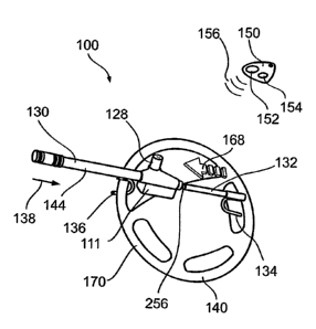
Figure 1 is a schematic diagram of a vehicle disabling system 100 installed in
a vehicle 102. According to an embodiment of the invention system 100
iticludes a
biasable locking cotnponent or lockable crosspiece 144 that is shown biased
against a
vehicle steering wlieel 140 - a movable driving component.
In an exemplary embodiment, in response to transmission of wireless signals
156 from a hand-held wireless transceiver 150 a ratchet extension 117 (Figure
3) is
activated and removed from ratchet 256, allowing unbiasing and reinoval of
crosspiece 144 from steering wheel 140 as explained below.
Additionally, system 100 includes an electronic relay 142 having a wireless
transceiver 143 that receives wireless signals 156 from handheld transceiver
150. In
an exemplary embodiment, upon shutting vehicle 102 by shutting a motor
ignition
160, relay 142 disables motor ignition 160 in a manner that prevents
activation of
ignition 160 until transceiver 143 receives signals 156. Thus, relay 142
effectively
itntnobilizes vehicle 102.
Additionally or alternatively, relay 142 is connected to alternative
electronic
components including, inter alia, a brake lock 146 and/or a fuel pump 148.
In an exemplary embodiment, relay 142 including transceiver 143 is
configured to fit a standard vehicle-inunobilizing relay receptacle.
Additionally, relay
142 incotporates polarity independent circuitry so that relay 142 is empowered
by the
availability of voltage between any pair of contacts on relay 142. These
features
ensure that relay 142 is easily retrofitted in a postproduction vehicle in a
simply
procedure that, in sonZe instances is performed by the driver of vehicle 102.
CA 02618437 2008-02-07
WO 2007/020637 PCT/IL2006/000946
7
An exemplary description of an immobilizer relay 142 that can be installed in
a standard relay receptacle is seen in Pending U.S. Patent Applications
10/275,212
and 10/883,858, filing dates, Noveniber 1 2002 and July 2 2004, respectively.
In exemplary embodiments, handheld transceiver 150 includes a key ring 153
to conveniently attach thereto a key 174 used in nlanually addressing a key
lock 124
on crosspiece 144 as will be explained below.
In addition, liandheld transceiver 150 includes a first actuator button 152
and
second activator button 154 that produce a first wireless signal 156 and a
second
wireless signal 157.
In som.e embodinlents, as described above, first wireless signals 156 are
received by crosspiece transceiver 125 and relay transceiver 143 to allow
removal of
crosspiece 144 and enablement of relay 142 respectively. In such enibodiments,
button 154 is optionally utilized to send wireless signals 157 to activate a
wireless
receiver and opener 104 associated with a fuel hatch 106.
In other enibodiments, signal 156 activates crosspiece transceiver 125, while
signal 157 activates relay transceiver 143. As will be explained below,
signals 156
and/or 157 optionally comprise any type of wireless signai, including radio
frequency
(RF) and in.fiared signals; the many configurations of buttons 152 and 154 and
types
of signals 156 and 157 produced, being well-known to those familiar with the
art.
Figure 2A shows an exemplary lockable crosspiece 144 in greater detail,
including a manual key lock 128, mechanism housing 111. A bar 132 having a
first
positioning hook 134, slides into a hollow tube 130 having a second
positioning hook
136.
Figure 2B shows exemplary deployment of crosspiece 144 on steering wheel
140 in which positioning hook 136 is positioned against a rim 170 of steering
wheel
140 and bar 132 is advanced out of hollow tube 130 in a direction 138 so that
positioning hook 134 presses against steering wheel rim 170. Ratchets 256
positioned
along bar 132 interface with a locking mechanism explained below, locking
crosspiece 144 on steering wlieel 140.
To utilock crosspiece 144 using handheld transceiver 150, actuator button 152
is pressed to causes emission of a wireless signal 156, that is received by a
wireless
receiver 125 (shown in figure 3) within housing 111, that causes a drive 123
to rotate
a worm gear 162 against a first gear 164, which causes a second gear 166 to
rotate,
CA 02618437 2008-02-07
WO 2007/020637 PCT/IL2006/000946
8
thereby actuating a lever that presses against a ratchet barrel 113 causing
ratclzet
extension 117 to remove from ratchets 256, allowing movement of bar 132 into
tube
130.
Returning to Figure 2C, with ratchet 256 unlocked, bar 132 is manually
retracted toward housing 111 in direction 168 so that positioning hook 134
disengages
from wheel ri.un 170, allowing tube 130 to move in direction 138, thereby
allowing
disengagement of positioning hook 136 from rim 170.
Figure 2D shows key 174 being moved in a direction 176 to engage lock 128
and turn lock in a direction 178. As seen in Figure 3, lock 128 engages a
swivel pin
191 that rotates to engage a piston 119. As swivel pin 191 rotates in
direction 178,
piston 119 moves in a direction 195 in a shaft 180, thereby pulling extension
117
from ratchets 256 and allowing bar 132 to move into tube 130 so that
crosspiece 144
may be removed from steering wheel 140 as shown in Figure 2D.
Alternative Enibodiments
Figure 4A shows crosspiece 144 being biased between a handbrake lever 182
and a vehicle chassis surface 184.
Figure 4B shows system 200 in which crosspiece 144 is biased between a gear
shifter 192 and a securing post 197; the many applications of crosspiece 144
being
well-known to those familiar with the art.
In an exemplary embodunent, system 200 demonstrates the disanning of
crosspiece 144 in preparation for driving. Initially, the driver enters
vehicle 102 and
presses a docking button 190 located on housing 111 so that drive transceiver
125
sends a signal 194 that is received by handheld transceiver 150. in some
embodiments, transceiver 150 automatically sends autocnatic wireless signals
193 to
drive transceiver 125 and within a period of time, for example two or three
seconds,
crosspiece 144 will automatically unlock and immobilizer relay 142 will
mobilize
ignition 160 so that veliicle 102 is drivable. The driver can then remove and
store
crosspiece 144.
In alternative embodiments, for example when handheld trazisceiver 150
operates in manual mode, the driver enters vehicle 102 and presses button 190
which
generates signal 194. The driver then presses button 152 to generate wireless
signals
CA 02618437 2008-02-07
WO 2007/020637 PCT/IL2006/000946
9
157 so that crosspiece 144 is released and inunobilizer relay 142 mobilizes
ignition
160.
Should the driver not start vehicle 102 within a set period of time, for
example
within 20-30 seconds after pressing button 152, innnobilizer relay 142
reactivates
inunobilization of the ignition.
In an exemplary embodiment, when leaving vehicle 102, the driver merely
biases crosspiece between post 197 and gearshift 192 and presses button 190;
after
which crosspiece 144 automatically locks and inunobilizer relay 142
inunobilizes
ignition 160.
to Wlien using handlield transceiver 150 in nianual mode, following biasing of
crosspiece 144, the driver presses button 190 and then button 152 to initiate
the
above-noted irmnobilization process.
Note that in some embodiments, for example when crosspiece 144 is not
easily accessed, the driver presses button 154 to activate immobilizer relay
142 alone.
Additionally or alternatively, the driver can utilize any additional systems
rvith respect
to vehicle 102. For example to activate relay 142, the driver may use a liand
held
device 105 comprising inter alia, a separate handheld wireless immobilizer or
a
wireless pager.
Electronic Circuitry
Referring to Figure 5, we find the circuitry of system 100, which includes a
remote control receiver, 201. The decoding of the randoin encrypted codes is
done in
processor 202. Timing and driving pulse for the motor are also generated in
processor
202. Transistors 203, 204, 205 and 206 provide drive capability for the niotor
Ml,
which latches or unlatches the pin to the mechanical steering wheel lock.
To extend the life of the battery supply, the receiver is optionally in a
"sleep
mode" and is revived by pressing button 210 on the system before deactivation.
In an
exenlplary embodiment, the power source is 204 x AAA Alkaline batteries; and
does
not exclude other types of batteries such as Lithium and its derivatives.
In embodiments, diode 208 provides polarity protection as well as dropping
the 6 volts to approximately 5 .3 volts suitable for operating the 5 volt
processor.
Rechargeable batteries are optionally used in conjutiction with a charging
socket
provided on the system components.
CA 02618437 2008-02-07
WO 2007/020637 PCT/IL2006/000946
The miit is optionally plugged into the cigarette lighter socket. In an
exemplary embodiment, a 3 -4 year life can be expected from the batteries.
In embodiments, pseudo random or other encryption is used for the RF
coding. The code received is optionally transmitted by a remote controlled
5 transmitter, manually operated or by a remote control operated automatically
by
movement or other means, the latter offering automatic deactivation. Within 2
seconds of pressing the "wake up" button on the system, the system unlocks if
the
driver of the vehicle car-ries the special remote.
Optionally, plugging a small unit, which contains an encoder and transmitter,
10 into the cigarette lighter socket, deactivates the system on turning on the
vehicle's
ignition.
System 100 is designed to work with different RF remote control units.
The coding for corrununication between the remote control and the receiver in
the electronic unit attached to the steering wheel lock is optionally
encrypted using
64-bit encryption. The output from the processor provides drive via a buffer
to
energize the open/shut motor.
A signal from a remote control is received by the electronic docking unit and
decoded. It is compared with the stored codes in the processor niemory and if
a match
is found, a signal is suitably shaped, timed and buffered to drive a loiv
cuiTent motor
which drives a pin to release or close the locking mechanism of a typical
steering
wheel lock.
In an exemplary embodiment, the unit is powered by 4 x AAA batteries 209.
Rechargeable batteries are optionally used in conjunction with a charging
socket
included in the docking housing. NiCd, NiMh, Li.lon type batteries, iuter
alia, are
optionally be used. In an exemplary embodiment, a 2-year life is expected from
Alkaline AAA batteries.
It is appreciated that certain features of the invention, which are, for
clarity,
described in the context of separate embodiments, may also be provided in
combination in a single enlboditmnt. Conversely, various features of the
invention,
which are, for brevity, described in the context of a single embodiment, may
also be
provided separately or in any suitable subcombination.
CA 02618437 2008-02-07
WO 2007/020637 PCT/IL2006/000946
11
Although the invention has been described in conjunction with specific
embodiments thereof, it is evident that many alternatives, modifications and
variations
will be apparent to those skilled in the art.
Accordingly, the invention is intended to enibrace all such alternatives,
s modifications and variations that fall within the spirit and broad scope of
the
appended claims. All publications, patents and patent applications mentioned
in this
specification are herein incorporated in their entirety by reference into the
specification, to the same extent as if each individual publication, patent or
patent
application was specifically and individually indicated to be incorporated
herein by
reference. In addition, citation or identification of any reference in this
application
shall not be construed as an admission that such reference is available as
prior at-t to
the present invention.