Note: Descriptions are shown in the official language in which they were submitted.
CA 02618457 2008-01-15
PATENT
Docket No: 475411
MODULAR WEIGHT SYSTEMS FOR AUTOMOBILES
RELATED APPLICATIONS
[0001] This application claims the benefit of priority to U.S. Provisional
Patent Application Serial No. 60/885,088, filed January 16, 2007, which is
hereby
incorporated by reference in its entirety.
BACKGROUND
[0002] Due to their design and intended use, a number of vehicles contain
a significant amount of empty space (e.g., pick-up trucks, cargo vans,
minivans,
trailers, 18-wheelers). This empty space creates a weight imbalance that tends
to
reduce a driver's control on snow and ice. In an attempt to increase traction,
many
owners of lightweight vehicles place cinder blocks, bricks, sand bags, logs or
other
heavy items in the cargo space of their vehicles. Not only does this practice
reduce
the useful area within the vehicle, it also creates a serious risk of injury
or death if the
items become flying projectiles during an accident or sudden stop.A somewhat
safer
weighting device is a large rectangular water bladder that may be filled with
a garden
hose and placed in a trunk of a car or bed of a pick-up truck. However, these
bladders
contain between 12.5 and 50 gallons of water and weigh between 100 and 400
pounds
when full. A puncture of the bladder can therefore release large quantities of
water
within a trunk or car interior, and removal of an intact bladder may be
difficult or
impossible when the water within it is frozen. Further, these water bladders
have
convex top surfaces that are unsuitable for the stable transport of most
items.SUMMARY
[0004] The present instrumentalities overcome the problems outlined
above by providing modular weight systems for automobiles. The modular weight
systems disclosed herein include a plurality of tiles that may be placed in an
automobile cargo space. The tiles are configured to be joined together in a
releasably
mateable fashion so that the weight systems do not obstruct the cargo space or
become dislodged during movement.
[0005] In an embodiment, a modular weight system for an automobile
1
CA 02618457 2008-01-15
includes a first tile and a second tile, the first tile and the second tile
configured to
releasably mate to one another to form the modular weight system. The first
tile and
the second tile each have a surface area (in inches) to weight (in pounds)
ratio of less
than 30:1.
[0006] In an embodiment, a modular weight system for an automobile
includes a first tile and a second tile, the first tile and the second tile
configured to
releasably mate to one another to form the modular weight system. The first
tile and
the second tile each weigh at least twenty pounds and have a surface area (in
inches)
to weight (in pounds) ratio of less than 30:1.
[0007] In an embodiment, a method of using a modular weight system to
improve automobile traction includes providing a first tile and a second tile,
the first
tile and the second tile configured to releasably mate to one another to form
the
modular weight system. The first tile and the second tile each have a surface
area (in
inches) to weight (in pounds) ratio of less than 30:1. The modular weight
system is
placed in a cargo space of an automobile.
BRIEF DESCRIPTION OF THE FIGURES
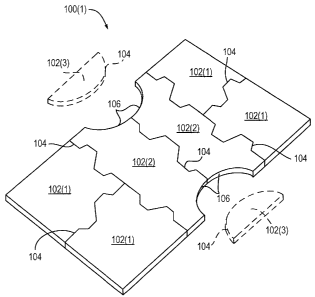
[00081 FIG. I is a top perspective view of an exemplary modular weight
system configured for placement in a bed of a pick-up truck.
[0009] FIG. 2 is a top plan view of an exemplary modular weight system
configured for placement in a square or rectangular cargo space of an
automobile.
[0010] FIG. 3 is a top perspective view of a tile having an internal cavity,
according to an embodiment.
[0011] FIG. 4 is a top perspective view of a tile having an internal cavity
and a hinged lid, according to an embodiment.
[0012] FIG. 5 is a partial cutaway view of a tile having a doped inner
material and an outer coating, according to an embodiment.
[0013] FIG. 6 is a top perspective view of a tile including a top portion
and a bottom portion that are bonded together.
DETAILED DESCRIPTION
[0014] As used herein, the term "automobile" refers to a device for the
2
Docket No.: 475411
CA 02618457 2008-01-15
ground transportation of passengers or cargo, where the device may or may not
be
independently powered. For example, the term "automobile" may refer to various
types of cars, buses, pick-up trucks, flatbed trucks, trailers, 18-wheelers,
cargo vans,
minivans, SUV's and the like.
[0015] As used herein, "mating" of tiles may be accomplished when two
or more tiles are sized and shaped to join or fit together in an
interconnected and
interlocking manner. Interlocking of mated tiles provides a substantially snug
fit,
such that motion of each tile is constrained relative to the tile(s) with
which it is
mated, and little or no space exists between the edges of mated tiles. For
example,
two or more tiles may be mated using interlocking or interdigitated tabs.
[0016] Reference will now be made to the attached drawings, where like
numbers represent similar elements in multiple figures. Numbering without
parentheses is used to denote a genus (e.g., modular weight system 100),
whereas
numbering with parentheses denotes a species within a genus (e.g., modular
weight
system 100(2)). Multiple elements within a figure may not be labeled for the
sake of
clarity.
[0017] FIG. I is a top perspective view of an exemplary modular weight
system 100(1) configured for placement in a bed of a pick-up truck (not
shown). In
operation, modular weight system 100(1) is sized and shaped to fit snuggly
within the
bed of a particular model and brand of truck, thereby minimizing movement of
system
100(1) during driving. Modular weight system 100(1) includes a plurality of
individual tiles 102(1) and 102(2), which are releasably mated to one another
at edges
104 of tiles 102 (e.g., by aligning edges 104 and setting them in place with a
rubber
mallet). Within system 100(1), tiles 102(1) are configured as corner pieces,
and tiles
102(2) are configured as center pieces having cutout portions 106 to
accommodate
wheel wells of a pick-up truck.
[0018] In an alternate embodiment, when it is unnecessary to
accoinmodate wheel wells of an automobile, tiles 102(3) may be aligned with
cutout
portions 106. In one example, tiles 102(3) may contain interlocking tabs for
mating
of tiles 102(3) with tiles 102(2). Use of tiles 102(3) converts system 100(1)
into a
rectangular weight system similar to system 100(2) of FIG. 2.
[0019] Although FIG. I shows six (or eight) tiles 102, it will be
3
Docket No.: 475411
CA 02618457 2008-01-15
appreciated that various layouts involving two, three, four, five, six, seven,
eight,
nine, ten or more tiles 102 may be used to create modular weight system 100.
Modular weight system 100 may form various regular or irregular shapes without
departing from the spirit and scope of what is described herein. Further, tabs
202
(FIG. 2), which are used to releasably mate edges 104 of tiles 102, may be
formed in
various sizes and shapes.
[0020] FIG. 2 is a top plan view of one exemplary modular weight system
100(2) configured for placement in a square or rectangular cargo space of an
automobile, such as a trunk or trailer. Length, L, and width, W, of system
100(2) may
be adjusted to accommodate cargo spaces of various sizes by the addition or
subtraction of tiles 102(4). As discussed above, tiles 102(3) may be used to
convert
system 100(1) into a rectangular system such as system 100(2). In another
embodiment, tiles 102(1) of FIG. 1 may be joined directly to form a square or
rectangular system such as system 100(2).
[0021] In general, tiles 102 have substantially flat top and bottom surfaces,
which provide for the stable transport of most items, and the tiles are
generally
fabricated from chemically inert and durable material(s). Tiles 102 may, for
example,
be fabricated from metal, rubber, plastic (e.g., polyurethane) or a
combination thereof
(e.g., silicon rubber coated metal). Rubber or plastic tiles 102 may be
fabricated using
well known extrusion and iiijection molding procedures, whereas metal tiles
102 may
be created using known metal working or melt casting techniques.
[0022] In an embodiment, use of materials which are resistant to
ultraviolet radiation (UV) may decrease a rate of decomposition of a modular
weight
system that experiences extended sun exposure (e.g., in an open pick-up
truck). UV
resistant material may be used to form a monolithic tile 102, or it may be
used as a
coating disposed around tile 102.
[0023] In an embodiment, a tile 102 may be fabricated, at least in part,
from a magnetic material, such as stainless steel, cerainic or iron oxide,
Fe304.
Magnetic attraction between the tile and body of the automobile may help to
immobilize the tile(s) during automobile movement. For example, a surface of
tile
102 intended to contact the automobile may be fabricated of stainless steel,
and other
surfaces, e.g., top and/or side surfaces, may be coated with a plastic, rubber
or UV
4
Docket No.: 475411
CA 02618457 2008-01-15
coating. In another embodiment, the magnetic field associated with a magnetic
material may be sufficient to penetrate a coating that covers the entirety of
tile 102.
[0024] The weight of each tile 102 is, for example, between 20 - 200
pounds, preferably between 40 - 100 pounds, and most preferably between 50 -
80
pounds. For personal vehicles, it is desirable that tiles 102 each weigh an
amount that
an average, healthy adult can lift without strain or injury. For commercial
vehicles,
heavier tiles may be used and, if necessary, the tiles may be placed in a
cargo space
using machinery (e.g., a fork lift). Modular weight systems 100 typically
weigh
between 40 - 2000 pounds, preferably between 100 - 1000 pounds, and most
preferably between 200 - 800 pounds.
[0025] Generally, each tile 102 has a width of about 24 - 75 inches, a
length of about 24 - 75 inches, and a height or thickness of about 1- 4
inches. Tiles
102 typically have a ratio of surface area (in inches) to weight (in pounds)
that is less
than 30:1, preferably between 2.5:1 to 25:1, more preferably between 3.5:1 to
15:1,
and most preferably between 4.5:1 to 10:1.
[0026] The weight of each tile 102 may be controlled by appropriate
selection of the fabrication material(s). In an embodiment, tile 102 may be
formed as
a monolithic mass where the physical weight of the fabrication material may be
sufficient to improve automobile traction. In another embodiment, tile 102 may
be
filled or doped with a heavy filler material, such as sand, stone or shot.
When the
filler material is stone or shot, for example, the material may have a
diameter between
0.1 and 1 inch, preferably between 0.1 and 0.5 inches. Additionally, a coating
may be
disposed around a monolithic tile, a filled tile, or a doped tile to maintain
integrity
and/or increase durability of the tile. For example, tile 102 may comprise a
monolithic steel plate coated with rubber.
[0027] FIG. 3 is a top perspective view of a tile 102(5) having an internal
cavity 302 for receiving filler material 304. Following insertion of filler
material 304
into cavity 302, a lid 306(1) may be factory bonded or glued to a base 308.
Alternatively, cavity 302 may be filled by an end user and lid 306(1) may
securely,
and optionally releasably, mate with base 308. In an embodiment, a latching
and/or
locking mechanism may be used to secure lid 306(1) to base 308. In another
embodiment, epoxy may be used to permanently mate lid 306(l) and base 308. As
Docket No.: 475411
CA 02618457 2008-01-15
described above with respect to FIG. 2, tabs 202 may releasably mate edges of
one
tile 102(5) with an adjacent tile 102(5).
[0028] FIG. 4 is a top perspective view of a tile 102(6) having an internal
cavity 302 and hinged lid 306(2). In addition to one or more hinges 402, tile
102 may
contain a latching and/or locking mechanism to secure filler material 304
within tile
102(6).
[0029] In another example, filler material 304 may be distributed
throughout the fabrication material. FIG. 5 is a partial cutaway view of one
tile
102(7) having a doped inner material 502 and an outer coating 504. For
example,
inner material 502 may be rubber doped with a filler material 304 (e.g., steel
shot),
which is then encased within a coating 504 of silicone rubber. In another
embodiment, inner material 502 and coating 504 may be formed of the same
fabrication material (e.g., rubber) except that inner material 502 may be
doped and
coating 504 may not contain filler material. In yet another embodiment, inner
material 502 may be doped with a fine grain filler material 304, such as sand,
and
coating 504 may not be present.
[0030] FIG. 6 is a top perspective view of a tile 102(8) having a top
portion 602 and a bottom portion 604 that are permanently or semi-permanently
bonded together. For example, top and bottom portions 602, 604 may be bonded
together using epoxy, rubber cement, glue, caulk, welding material or another
bonding material known in the art. Although FIG. 6 shows tile 102(8)
containing
only two portions 602 and 604, it will be appreciated that tile 102(8) may
alternatively
include three, four, five, ten, twenty or more portions.
[0031] In an embodiment, top portion 602 and bottom portion 604 may be
similarly shaped so that there are no overhanging parts when portions 602 and
604 are
aligned and bonded. In another embodiment (shown in FIG. 6), top portion 602
and
bottom portion 604 have different shapes, and one or more overhanging parts
606
exist. It will be appreciated that a second tile 102(8)' (not shown) that is
configured
to be joined with tile 102(8) will have an arrangement of overhanging parts
606 that is
complementary to that of tile 102(8). Tiles 102(8) and 102(8)' may therefore
be
interdigitated or interlocked along a vertical axis defined by the thickness
of a tile
102. Interdigitation along the vertical axis, as well as along the lateral and
6
Docket No.: 475411
CA 02618457 2008-01-15
longitudinal axes (FIG. 2, L and W) using tabs 202, provides improved
stability
during vehicle movement.
[0032] In one example, one or more overhanging parts 606 of tile 102(8)
may be bonded to one or more complementary overhanging parts 606' of tile
102(8)'.
Bonding of the overhanging parts 606, 606' may be permanent, semi-permanent or
temporary. For example, temporary bonding may be accomplished using Velcro ,
magnets, reusable adhesives and/or other means known in the art.
[0033] Changes may be made in the above systems and methods without
departing from the scope hereof. It should thus be noted that the matter
contained in
the above description or shown in the accompanying drawings should be
interpreted
as illustrative and not in a limiting sense. The following claims are intended
to cover
all generic and specific features described herein, as well as all statements
of the
scope of the present systems and methods, which, as a matter of language,
might be
said to fall there between.
7
Docket No.: 475411