Note: Descriptions are shown in the official language in which they were submitted.
CA 02618582 2008-01-18
=
01204.044000
- 1 -
TITLE
RETRACTING SAFETY PEN NEEDLE
BACKGROUND OF THE INVENTION
Field of the Invention
[0001] The invention is directed to a passive safety system that may be
associated with an injection pen needle to protect a patient and/or healthcare
professional using the pen needle from accidental needle sticks. The pen
needle
according to the invention provides for the non-injection end of a needle in a
pen
needle to be retracted into the device for safety.
Description of the Related Art
[0002] Accidental needlestick injuries from contaminated needles expose
healthcare workers to the risk of infection from blood-borne pathogens,
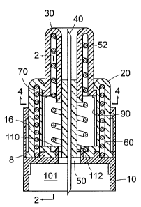
including
the viruses that cause hepatitis B and C, and HIV. According to the Centers
for
Disease Control and Prevention, healthcare workers in the United States
experience an estimated 600,000 exposures to blood each year, with RNs
sustaining an overwhelming majority of these incidents.
[0003] While the injection device of choice in the U.S. remains the syringe,
the
demand for pen needles is growing rapidly. The use of self-injection pen
needle
devices is increasing due to the relative convenience, portability, and ease
of use
of these devices as compared to single use syringes. Pen needles are also
CA 02618582 2008-01-18
- 2 -
becoming more commonplace in the hospital/clinical setting because certain
drugs, such as human growth hormone and osteoporosis medications, are
available only in pen needle form.
[0004] Healthcare workers have sustained needlestick injuries while removing
pen needles from injection devices and subsequently disposing of them after
administering an injection to patients. The needles are typically removed
after
each injection to minimize contamination of the medication in the cartridge
and
to prevent needle re-use. Removal of the needle generally requires the re-
shielding of the injection end (also referred to herein as the "patient end")
of the
needle using the outer protective cover in which it was supplied. Injuries
from
the patient end of the needle commonly occur at this time, but they can also
occur
during the removal of the pen needle from the pen as a result of the exposed
non-
patient end of the needle. To wholly address the problem of needle stick
injuries,
it would be desirable to have pen needles with safety features on both ends of
the
needle.
[0005] U.S. Patent No. 6,986,760 B2, assigned to the assignee of the present
application, teaches a pen needle and safety shield system wherein a safety
shield, which normally encloses the needle cannula prior to use, permits
retraction of the safety shield during injection and automatically extends and
locks the shield in the extended enclosed position following use. The pen
needle
also prevents retraction of the shield during assembly of the shield and
needle
cannula and hub assembly on the pen injector.
[0006] U.S. Patent No. 6,855,129 B2 discloses a safety needle assembly having
a
cylindrical housing with a needle mounted thereon for mounting onto a medical
injection device. A shield is telescopically movable relative to the housing
between a distal position, in which the shield covers the end of the needle,
and a
proximal position, in which the needle is exposed. A spring located inside the
housing urges the shield in the distal direction. A locking element on the
device is
provided inside the housing with outwardly pointing locking protrusions. The
locking element is a separate part provided between the spring and the shield
and
it is longitudinally moved simultaneously with the shield relative to the
housing
during use, so that the protrusions on the locking element are guided from a
first
CA 02618582 2008-01-18
,
- 3 -
position where the shield is in the distal position, to a second position
where the
shield is in the proximal position, to a third position where the locking
protrusions are blocked by a blocking surface provided on the inside surface
of
the housing, so that further movement of the shield is irreversibly
immobilized.
[0007] In contrast to the prior art, where the needle is fixedly mounted in a
hub,
in the present invention, the needle is movable with respect to the hub and
may
thus be retracted to a safe position within the hub after an injection is
administered. Thus, the present invention addresses the need for a safety
mechanism on the non-patient end of the needle.
SUMMARY OF THE INVENTION
[0008] In one aspect of the invention, a non-injection end passive safety
system
for a pen needle comprises: a) a needle having an injection end and a non-
injection end; b) a hub housing the principle components of the device,
including
a needle carrier and a shield; c) a needle carrier firmly securing the needle,
situated in and moving coaxially with respect to the hub; d) a shield having a
travel element engaging a corresponding element in the carrier, permitting
axial
movement of the shield with respect to the carrier and engaging a locking
element on the carrier to lock the shield in a position covering the needle;
e) a
shield return spring biasing the shield in a direction away from the carrier
toward
the injection end of the needle; and 1) a carrier activation spring biasing
the
carrier in a direction away from the hub in a direction toward to the
injection end
of the needle. The device is assembled so that, after an injection is
administered,
the carrier moves the needle toward the injection end and into the body of the
hub, effectively storing the needle within the hub to safely shield the
needle.
BRIEF DESCRIPTION OF THE FIGURES
[0009] Fig. 1 is a cross section of the injector pen needle showing the hub,
carrier and shield.
[0010] Fig. 2 is a cross sectional detail of the device shown in Fig. 1,
viewed
along line 2-2, showing the engagement mechanism between the shield and the
carrier.
CA 02618582 2008-01-18
- 4 -
[0011] Fig. 3 shows the system of Fig. 1, with the patient-end shield in the
full
locked out position, and the non-patient end of the needle retracted into the
hub.
[0012] Fig. 4 is a cross sectional detail of the device shown in Fig. 1,
viewed
along line 4-4, showing the engagement mechanism between the shield and the
carrier.
[0013] Fig. 5 is a detail showing the mechanism for releasing the carrier from
the hub.
[0014] Fig. 6 is a detail showing the mechanism for releasing the carrier from
the hub in a released position.
[0015] Fig. 7 shows a shield with a shield insert.
DETAILED DESCRIPTION OF THE PREFERRED EMBODIMENTS
[0016] The safety shield system according to the invention is "passive"
because
the shielding of the non-injection end of the needle is automatic upon
administering an injection, as the needle is drawn into the hub. In other
words,
user-executed steps are not required specifically to shield the needle.
[0017] As used herein, the terms "injection end" and "non-injection end" refer
to
directions on the device, regardless of whether the particular element is
involved
in the injection. Thus (for example only) the hub and the shield both have an
injection end and a non-injection end. The injection end is toward the end of
the
device that is normally pressed against a patient's body to administer an
injection, and the non-injection end is toward the opposite end of the device.
[0018] A pen needle is generally longer than it is wide. Movement on the
longitudinal axis is referred to herein as "axial" movement. The perpendicular
direction is the "radial" direction, and the direction traveled when an
element is
twisted around the longitudinal axis is the "circumferential" direction. As
used
herein, the injection or non-injection end of the needle is "covered" when the
tip
of the end of the needle does not extend beyond the end wall of the shield, or
beyond the recess in the hub, notwithstanding that the tip of the needle may
be
quite close to the aperture in the shield or hub, and exposed to view.
[0019] Fig. 1 illustrates an embodiment of the retracting passive safety
shield
system according to the invention in the state that it is removed from its
CA 02618582 2008-01-18
- 5 -
packaging and is ready for use. The system includes a hub 10, which attaches
to
the pen injector (not shown) via recess 101, and houses the other components,
including carrier 20, shield 30, and a needle 40. The hub 10 has a recess 101
to
receive a pen-injector in the non-injection end, and an aperture 50 to permit
passage of the needle 40 into the medication within the pen injector. The term
"pen injector" (also sometimes referred to as the "cartridge") may refer to
the
cartridge housing, or to the housing together with the enclosed medication
vial, as
the context requires. The needle 40 is securely mounted on the carrier 20,
which
is situated on the hub 10. The carrier/needle assembly is movable with respect
to
the hub, as described below.
[0020] The materials of construction are not critical. The structural
elements,
such as the hub, shield and needle carrier are typically injection molded
parts,
whereas the needle and springs are typically metal.
[0021] In Fig. 1, the shield 30 is in an extended position, covering the end
of the
needle. In use, the shield 30 is forced into the hub to allow injection,
compressing spring 52 as the device is pressed against a patient's skin,
exposing
the needle to the patient's tissue. The spring thereafter exerts force on the
shield
so that it again covers the injection-end of the needle 40 after injection.
The
carrier 20 holds the needle 40 firmly in place and is secured to the hub 10
until
after injection, when the carrier is released from the hub 10 (as described
below),
and moves, with the needle 40, toward the injection end and into the body of
the
hub 10, effectively storing the needle 40 in the hub 10 prior to the user
removing
the pen injector. This prevents accidental needle sticks that can occur at the
non-
injection end of the device.
[0022] In the initial stages of an injection, shield 30 moves with respect to
carrier
20 in an axial direction with a travel element on the shield engaging a
corresponding element on the carrier permitting axial movement of the shield
with respect to the carrier. For example, the shield may comprise buttons 70
on
the base of the shield engaging corresponding tracks 130 and 90 in the
carrier, as
shown in the details of Fig. 2. As shield 30 is pressed during an injection,
the
buttons 70 travel in corresponding tracks 130, and at the full travel
position, one
or more buttons are guided into return track 90. When the shield is fully
CA 02618582 2014-05-26
- 6 -
extended, the shield lock out detent 150 captures the button 70 and locks the
shield in place. The buttons 70 are preferably spaced equidistantly around the
base of the shield 30, for example, three buttons may be located 120 degrees
apart from one another.
[0023] In the embodiments shown, an element on the hub engages with a
corresponding element on the carrier to releasably lock the carrier to the
hub.
"Releasably" in this context means that through the normal operation of the
device, the needle carrier is enabled to move axially within the hub. For
example, three axially extending tabs 110 on the hub, inboard of the radial
side
wall of the hub, may engage corresponding edges of through holes 112 on the
carrier, fixing the carrier in place while the shield moves axially toward the
hub
during the initial stages of an injection. Thereafter, as shown in Fig. 4 and
Fig.
5, the leading edge 19' of the shield may be shaped to press the tabs 110
inward,
freeing the carrier when the shield reaches its full travel position. The
force of
the spring 60 then forces the carrier toward the injection end, retracting the
needle within the hub.
[0024) Additionally or as an alternative, through holes or recesses on a
radial
side wall of the hub may engage corresponding elements on the carrier to
releasably lock the carrier to the hub, in such a way that installing the
cartridge
on the hub (typically, but not necessarily, by rotating the cartridge into a
threaded
connection, which also rotates the needle carrier) frees the carrier. Thus,
the
carrier is unlocked in its initial state, held in place by the penetration of
the
needle into the septum of the cartridge/vial. This feature may be used in the
absence of the above-described axially extending lock down tabs 110, or
together
with the tabs as an additional lock down mechanism.
[0025] During an injection, when the buttons 70 on the shield move in the
circumferential direction from axial tracks 130 to track 90 in the carrier 20,
the
shield will want to rotate a small amount. The distance of circumferential
movement may be very small, such as less than 1 mm, and preferably in a range
of 0.100 mm to 0.250 mm, but nevertheless perceptible by the user. Any
discomfort can avoided by use of a shield insert 210. As shown in Fig. 7, the
shield insert 210 attaches to the shield and is movable with respect to the
shield,
CA 02618582 2008-01-18
-7...
so that pressed against the skin of a patient during an injection, the shield
insert
remains stationary while the shield rotates.
E0026] This invention can be applied to any injection device incorporating a
dual
end (injection / non-injection) injection needle configuration, delivering
medication (or other substances) into a body space (or other locations) where
it
would be advantageous to have dual end passive safety features to protect
users
(self-injectors or health care workers) from accidental needle sticks and
exposure
to biohazardous substances or other hazardous liquid substances. The examples
taken from the preferred embodiments and described above, are for
illustration,
and are not to be deemed to limit the invention, which is defined by the
following
claims.