Language selection

Search

Patent 2618584 Summary

Third-party information liability

Some of the information on this Web page has been provided by external sources. The Government of Canada is not responsible for the accuracy, reliability or currency of the information supplied by external sources. Users wishing to rely upon this information should consult directly with the source of the information. Content provided by external sources is not subject to official languages, privacy and accessibility requirements.

Claims and Abstract availability

Any discrepancies in the text and image of the Claims and Abstract are due to differing posting times. Text of the Claims and Abstract are posted:

  • At the time the application is open to public inspection;
  • At the time of issue of the patent (grant).
(12) Patent: (11) CA 2618584
(54) English Title: A METHOD OF CONSTRUCTION FOR A LOW COST PLASTIC ULTRASONIC WATER METER
(54) French Title: PROCEDE DE CONSTRUCTION D'UN COMPTEUR D'EAU ULTRASONIQUE EN PLASTIQUE A FAIBLE COUT
Status: Deemed expired
Bibliographic Data
(51) International Patent Classification (IPC):
  • G01F 15/00 (2006.01)
  • G01F 15/14 (2006.01)
  • G01F 15/18 (2006.01)
  • G01F 1/66 (2006.01)
(72) Inventors :
  • RHODES, SIMON JOHN (United Kingdom)
(73) Owners :
  • FLOWNETIX LIMITED (United Kingdom)
(71) Applicants :
  • FLOWNETIX LIMITED (United Kingdom)
(74) Agent: SMART & BIGGAR IP AGENCY CO.
(74) Associate agent:
(45) Issued: 2014-09-30
(86) PCT Filing Date: 2006-07-28
(87) Open to Public Inspection: 2007-02-22
Examination requested: 2011-06-30
Availability of licence: N/A
(25) Language of filing: English

Patent Cooperation Treaty (PCT): Yes
(86) PCT Filing Number: PCT/GB2006/002825
(87) International Publication Number: WO2007/020375
(85) National Entry: 2008-02-07

(30) Application Priority Data:
Application No. Country/Territory Date
0516754.9 United Kingdom 2005-08-13

Abstracts

English Abstract


There is described an ultrasonic flow meter comprising a pipe having two ends,
electronic circuitry, a first enclosure housing the electronic circuitry, a
second enclosure housing the pipe, and a plurality of ultrasonic transducers
attached to an external surface of the pipe in the second enclosure. The first
enclosure is watertight, whereas the second enclosure is not watertight. The
two ends of the pipe protrude from the second enclosure. Each transducer is
covered by a respective cap and sealed from water ingress. Each transducer is
connected to the electronic circuitry by a respective pair of wires.


French Abstract

La présente invention concerne un compteur de flux ultrasonique comprenant une conduite avec deux extrémités, un circuit électronique, une première enceinte logeant le circuit électronique, une seconde enceinte logeant la conduite et une pluralité de transducteurs ultrasoniques fixés à une surface externe de la conduite de la seconde enceinte. La première enceinte est imperméable, tandis que la seconde ne l'est pas. Les deux extrémités de la conduite dépassent de la seconde enceinte. Chaque transducteur est couvert par un bouchon respectif et empêche l'entrée d'eau. Chaque transducteur est relié au circuit électronique par une paire respective de câbles.

Claims

Note: Claims are shown in the official language in which they were submitted.


- 6 -
CLAIMS:
1. An ultrasonic flow meter comprising:
a pipe having two ends;
electronic circuitry;
a first enclosure housing the electronic circuitry,
the first enclosure being watertight;
a second enclosure housing the pipe, the two ends of
the pipe protruding from the second enclosure, the second
enclosure not being watertight; and
a plurality of ultrasonic transducers attached to an
external surface of the pipe within the second enclosure, each
transducer being covered by a respective cap and sealed from
water ingress, each transducer being connected to the
electronic circuitry by a respective pair of wires.
2. The ultrasonic flow meter of claim 1 in which:
the pipe comprises a U-tube, the U-tube comprising
two parallel side tubes joined together by a central tube; and
the ultrasonic flow meter comprises two ultrasonic
transducers, each transducer being attached to a respective end
of the central tube.
3. The ultrasonic flow meter of claim 2 in which a
diameter of each of the transducers is equal to an internal
diameter of the central tube.


- 7 -
4. The ultrasonic flow meter of claim 1 in which the
pipe is a straight pipe comprising a plurality of wedges for
mounting the transducers at an angle to a surface of the pipe.
5. The ultrasonic flow meter of any one of claims 1-4 in
which the first enclosure comprises a waterproof connector for
interfacing to external equipment.
6. The ultrasonic flow meter of any one of claims 1-5 in
which the first enclosure comprises an LCD display.
7. The ultrasonic flow meter of any one of claims 1-6 in
which the pipe is formed from a thermoplastic.

Description

Note: Descriptions are shown in the official language in which they were submitted.


CA 02618584 2008-02-07
WO 2007/020375
PCT/GB2006/002825
- 1 -
A METHOD OF CONSTRUCTION FOR A LOW COST PLASTIC ULTRASONIC
WATER METER
FIELD OF THE INVENTION
This invention relates to the creation of a flow
measurement cell and enclosure for an all-electronic water
meter.
BACKGROUND OF THE INVENTION
Traditional ultrasonic flow meters are industrial
instruments and are enclosed in rugged, usually metal, pipe
shaped transducer enclosures with integral or separately
mounted electronics.
The object of this invention is to package an
ultrasonic flow meter using plastics suitable for high
volume manufacture while giving the outward appearance
similar to a traditional mechanical water meter.
SUMMARY OF THE INVENTION
Accordingly this invention houses the section through
which the water flows, with a separate sealed section for
the electronic parts; the sealing allows operation when
submerged in water.
The water meter is typically made of engineering
plastics most suitable for the application. Typically this
will consist of a flow tube that carries the water flow
being measured, this being constructed of a strong,
mouldable thermoplastic approved for use with potable water
and an outer case comprising several sections to house the
flow tube, electronics and a lid to protect the display. All
materials used are suitable for use to the maximum operating
temperature.

CA 02618584 2013-08-20
20086-2332
- 2 -
In summary, according to the present invention, there
is provided an ultrasonic flow meter comprising a pipe
having two ends; electronic circuitry; a first enclosure
housing the electronic circuitry, the first enclosure being
watertight; a second enclosure housing the pipe, the two
ends of the pipe protruding from the second enclosure, the
second enclosure not being watertight; and a plurality of
ultrasonic transducers attached to an external surface of
the pipe within the second enclosure, each transducer being
covered by a respective cap and sealed from water ingress,
each transducer being connected to the electronic circuitry
by a respective pair of wires.
BRIEF DESCRIPTION OF THE DRAWINGS
A typical embodiment of the invention will now be
described with reference to the accompanying drawings in
which:
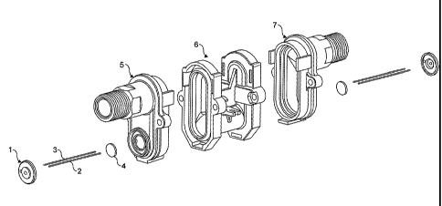
Figure 1 shows a U-tube implementation of a flow
measurement cell, typically used for pipes up to 25mm bore
size;
Figure 2 shows a straight tube, angled transducer
implementation of a flow measurement cell, typically used on
pipes over 25mm bore size;
Figure 3 shows how the internal parts (tube and
electronics) fit together with the outer enclosure; and
Figure 4 shows the detail inside the body that supports
the tube and prevents it rotating and sealed from the
electronics; and
Figure 5 shows the inside of the body from below.

CA 02618584 2008-02-07
WO 2007/020375
PCT/GB2006/002825
- 3 -
DETAILED DESCRIPTION OF A PREFERRED EMBODIMENT
As showing in Figure 1, the U-tube is constructed from
three main parts, two ends 5 and 7 and a centre body part 6.
This is needed so as to make the part mouldable using
injection moulding techniques.
The exposed pipe section of the end 5 is threaded to
accept standard fittings and also includes a flatted area
for use with spanners during fitting to reduce stress on the
tube/enclosure assembly as the fitting is tightened.
The two ends 5 are ultrasonically welded to the centre
body section 6 and can typically withstand pressures to 50
bar. The two transducers 4 with wires 2 and 3 already
attached are fixed into two locating rings on the ends of
the tube 5 using an epoxy resin. The wires are then passed
through a cap 1 that is placed over the transducers and then
sealed with a sealant. The transducers are now sealed from
water ingress. This is important as the case design allows
water to ingress into the bottom part of the enclosure while
allowing the equipment to continue to operate due to the
sealed transducers and electronics.
The transducer 4 is the same diameter as the inside
bore of the pipe so the ultrasonic signal passes through the
whole area of flowing liquid.
Figure 2 shows the same process for a straight through
flow tube. The tube is made in a single piece body 16 with
the wedges 18 being at an angle determined by the pipe
diameter and flow range required. Multiple transducer pairs
14 are used on the straight design to measure across a wider
area or extend the operating flow range in either a
reflection (vee) or diagonal (zee) configuration. Again,
caps 11 are placed over the transducers 14 and sealed to
protect the transducers from water ingress.

CA 02618584 2013-08-20
20086-2332
- 4 -
As shown in Figure 3, the electronic parts fit into the
top half of the enclosure body 111. The top cover 104 holds
the LCD viewing window 105 (ultrasonically welded in place
to ensure sealing), circuit board 106 secured by screws 107.
The battery 108 is supported in the main body 111. A
waterproof connector 109 interfaces to external equipment.
Such connectors usually have a nut that is tightened from
the outside so to prevent tampering a protective cover is
ultrasonically welded over the top. The assembled to cover
104, 105, 106 and 107 is screwed 103 to the main body 111
with an o-ring seal between. Tamper proofing is achieved by
putting the screw holes in the top cover 104 and covering
with a label 102 with serial number and other information
required by regulatory agencies. A flip over lid 101 clips
shut over the assembly to protect the display from direct
impacts.
The assembled tube (Figure 3 shows the u-tube
arrangement 112, 113, 114 and 115, similar for straight
tube) fits into the part of the main body 111 and is secured
using a screw 117 and support 116. Additional support is
provided by detail inside the body to support the tube and
prevent rotation.
The wires 113 are passed through the already fitted cap
112, through holes in the wall half way up the main body 111
to be connected to the electronics assembly in the top half.
Sealant is used around the wires where they pass through the
divider in the main body 111 to prevent any water ingress in
the bottom part of the enclosure reaching the top part.
The bottom of the body 111 is covered using a base part
118 which is attached using screws 119. The screw holes are
filled with an epoxy resin and plastic plugs 120 pushed into

CA 02618584 2013-08-20
20086-2332
- 5 -
the holes which are then sealed. Any tampering is therefore
destructive to the case and clearly evident.
Figure 4 shows the inside main body from above
including battery support 21, battery location 26, holes 25 for
wires 113 from the transducer assembly in the lower half to
pass through and support structures 24 for the u-tube 115.
Also shown are mounting points 2 for the top part 104 of the
case 111 and the o-ring seal 23 that ensures the electronics is
sealed from water ingress.
Figure 5a shows the inside of the main body from
below including supports 34 for the u-tube 115, holes 35 for
the transducer wires 113 to pass through, mounting points 38
for the bottom 18 of the case 111 and securing points 37 for
the tube 115. Figure 5b shows the tube 115 in position 39 with
screws in the supports 37. This prevents the meter from damage
by securing the tube 115 inside the case 111.

Representative Drawing
A single figure which represents the drawing illustrating the invention.
Administrative Status

For a clearer understanding of the status of the application/patent presented on this page, the site Disclaimer , as well as the definitions for Patent , Administrative Status , Maintenance Fee  and Payment History  should be consulted.

Administrative Status

Title Date
Forecasted Issue Date 2014-09-30
(86) PCT Filing Date 2006-07-28
(87) PCT Publication Date 2007-02-22
(85) National Entry 2008-02-07
Examination Requested 2011-06-30
(45) Issued 2014-09-30
Deemed Expired 2020-08-31

Abandonment History

There is no abandonment history.

Payment History

Fee Type Anniversary Year Due Date Amount Paid Paid Date
Application Fee $400.00 2008-02-07
Maintenance Fee - Application - New Act 2 2008-07-28 $100.00 2008-07-28
Maintenance Fee - Application - New Act 3 2009-07-28 $100.00 2009-07-02
Maintenance Fee - Application - New Act 4 2010-07-28 $100.00 2010-07-02
Maintenance Fee - Application - New Act 5 2011-07-28 $200.00 2011-06-29
Request for Examination $800.00 2011-06-30
Maintenance Fee - Application - New Act 6 2012-07-30 $200.00 2012-06-29
Maintenance Fee - Application - New Act 7 2013-07-29 $200.00 2013-07-10
Maintenance Fee - Application - New Act 8 2014-07-28 $200.00 2014-07-02
Final Fee $300.00 2014-07-17
Maintenance Fee - Patent - New Act 9 2015-07-28 $200.00 2015-07-03
Maintenance Fee - Patent - New Act 10 2016-07-28 $250.00 2016-07-07
Maintenance Fee - Patent - New Act 11 2017-07-28 $250.00 2017-06-30
Maintenance Fee - Patent - New Act 12 2018-07-30 $250.00 2018-06-29
Maintenance Fee - Patent - New Act 13 2019-07-29 $250.00 2019-07-25
Owners on Record

Note: Records showing the ownership history in alphabetical order.

Current Owners on Record
FLOWNETIX LIMITED
Past Owners on Record
RHODES, SIMON JOHN
Past Owners that do not appear in the "Owners on Record" listing will appear in other documentation within the application.
Documents

To view selected files, please enter reCAPTCHA code :


To view images, click a link in the Document Description column. To download the documents, select one or more checkboxes in the first column and then click the "Download Selected in PDF format (Zip Archive)" or the "Download Selected as Single PDF" button.

List of published and non-published patent-specific documents on the CPD .

If you have any difficulty accessing content, you can call the Client Service Centre at 1-866-997-1936 or send them an e-mail at CIPO Client Service Centre.


Document
Description 
Date
(yyyy-mm-dd) 
Number of pages   Size of Image (KB) 
Abstract 2008-02-07 1 70
Claims 2008-02-07 2 48
Drawings 2008-02-07 5 137
Description 2008-02-07 5 201
Representative Drawing 2008-05-01 1 15
Cover Page 2008-05-01 1 48
Description 2013-08-20 5 195
Claims 2013-08-20 2 41
Representative Drawing 2014-09-02 1 15
Cover Page 2014-09-02 1 48
Assignment 2008-02-07 4 155
Assignment 2008-02-07 3 110
PCT 2008-02-07 4 167
Correspondence 2008-02-11 2 71
Fees 2011-06-29 1 66
Prosecution-Amendment 2011-08-31 2 83
Maintenance Fee Payment 2019-07-25 1 55
Fees 2008-07-28 1 34
Correspondence 2008-07-17 2 142
Correspondence 2008-11-21 1 50
Correspondence 2009-06-01 1 48
Correspondence 2009-10-13 1 54
Fees 2010-07-02 1 34
Prosecution-Amendment 2011-06-30 2 79
Fees 2012-06-29 1 65
Prosecution-Amendment 2013-02-21 2 64
Correspondence 2014-03-03 1 53
Prosecution-Amendment 2013-08-20 18 697
Fees 2014-07-02 2 83
Correspondence 2014-07-17 2 75