Note: Descriptions are shown in the official language in which they were submitted.
CA 02618806 2008-02-11
WO 2007/021769 PCT/US2006/031081
DESCRIPTION
PROCESS AND APPARATUS FOR THE PRODUCTION OF
ENGINEERED CATALYST MATERIALS
Technical Field
[0001] The present invention relates to a process and apparatus for the
production of engineered nano-scale catalyst metal particles, such as non-
noble metal nano-scale particles, especially in a continuous manner. By
"non-noble metal" is meant a metal other than one of the noble metals
(generally considered to be gold, silver, platinum, palladium, iridium,
rhenium, mercury, ruthenium and osmium). By the practice of the present
invention, nano-scale catalyst particles can be produced with greater
precision, speed and flexibility than can be accomplished with conventional
processing, and the particles produced can be directly affixed to support
materials in a precise and cost-effective manner.
Background Art
[0002] Catalysts are becoming ubiquitous in modern chemical
processing. Catalysts are used in the production of materials such as fuels,
lubricants, refrigerants, polymers, drugs, etc., as well as playing a role in
water and air pollution mediation processes. Indeed, catalysts have been
ascribed as having a role in fully one third of the material gross national
product of the United States, as discussed by Alexis T. Bell in "The Impact of
Nanoscience on Heterogeneous Catalysis" (Science, Vol. 299, pg. 1688, 14
March 2003).
[0003] Generally speaking, catalysts can be described as small
particles deposited on high surface area solids. Traditionally, catalyst
particles can range from the sub-micron up to tens of microns. One example
described by Bell is the catalytic converter of automobiles, which consist of
a
honeycomb whose walls are coated with a thin coating of porous aluminum
oxide (alumina). In the production of the internal components of catalytic
converters, an aluminum oxide wash coat is impregnated with nanoparticles
of a platinum group metal catalyst material. In fact, most industrial
CA 02618806 2008-02-11
WO 2007/021769 PCT/US2006/031081
2
catalysts used today include platinum group metals especially platinum,
rhodium and iridium or alkaline metals like cesium, at times in combination
with other metals such as iron or nickel.
[0004] The size of these catalyst metal domains has been recognized as
extremely significant in their catalytic function. Indeed it is also noted by
Bell that the performance of a catalyst can be greatly affected by the
particle
size of the catalyst particles, since properties such as surface structure and
the electronic properties of the particles can change as the size of the
catalyst
particles changes.
[0005] In his study on nanotechnology of catalysis presented at the
Frontiers in Nanotechnology Conference on May 13, 2003, Eric M. Stuve, of
the Department of Chemical Engineering of the University of Washington,
described how the general belief is that the advantage of use of nano-sized
particles in catalysis is due to the fact that the available surface area of
small particles is greater than that of larger particles, thus providing more
metal atoms at the surface to optimize catalysis using such nano-sized
catalyst materials. However, Stuve points out that the advantages of the use
of nano-sized catalyst particles may be more than simply due to the size
effect. Rather, the use of nanoparticles can exhibit modified electronic
structure and a different shape with actual facets being present in the
nanoparticles, which provide for interactions which can facilitate catalysis.
Indeed, Cynthia Friend, in "Catalysis On Surfaces" (Scientific American,
April 1993, p. 74), posits catalyst shape, and, more specifically, the
orientation of atoms on the surface of the catalyst particles, as important in
catalysis. In addition, differing mass transport resistances may also improve
catalyst function. Thus, the production of nano-sized metal particles for use
as catalysts on a more flexible and commercially efficacious platform is being
sought. Moreover, other applications for nano-scale particles are being
sought, whether for the platinum group metals traditionally used for
catalysis or other metal particles.
[0006] Conventionally, however, catalysts are prepared in two ways.
One such process involves catalyst materials being bonded to the surface of
CA 02618806 2008-02-11
WO 2007/021769 PCT/US2006/031081
3
carrier particles such as carbon blacks or other like materials, with the
catalyst-loaded particles then themselves being loaded on the surface at
which catalysis is desired. One example of this is in the fuel cell arena,
where carbon black or other like particles loaded with platinum group metal
catalysts are then themselves loaded at the membrane/electrode interface to
catalyze the breakdown of molecular hydrogen into atomic hydrogen to
utilize its component protons and electrons, with the resulting electrons
passed through a circuit as the current generated by the fuel cell. One major
drawback to the preparation of catalyst materials through loading on a
carrier particle is in the amount of time the loading reactions take, which
can
be measured in hours in some cases.
[0007] To wit, in U.S. Patent 6,716,525, Yadav and Pfaffenbach
describe the dispersing of nano-scale powders on coarser carrier powders in
order to provide catalyst materials. The carrier particles of Yadav and
Pfaffenbach include oxides, carbides, nitrides, borides, chalcogenides, metals
and alloys. The nanoparticles dispersed on the carriers can be any of many
different materials according to Yadav and Pfaffenbach, including precious
metals such as platinum group metals, rare earth metals, the so-called semi-
metals, as well as non-metallic materials, and even clusters such as
fullerenes, alloys and nanotubes.
[0008] An additional drawback to the use of conventional carrier-
particle loaded catalysts lies in the fact that the typical method of applying
these materials to the support on which they are to be employed is by
forming a suspension of the particles in a fluoroelastomer and then painting
the admixed fluid onto the support, after which the suspension is "baked" to
bond the content to the support, leaving a coating of the catalyst coated
carrier particles on the surface of the support. This method does not allow
for a great deal of precision, resulting in the application of catalyst
material
at locations where it is not needed or desired. Given the cost of catalyst
materials, especially the noble metal materials typically considered most
efficacious, this "painting" method of application of catalysts is extremely
disadvantageous.
CA 02618806 2008-02-11
WO 2007/021769 PCT/US2006/031081
4
[0009] Alternatively, the second common method for preparing catalyst
materials involves directly loading catalyst metals such as platinum group
metals on a support without the use of carrier particles which can interfere
with the catalytic reaction. For example, many automotive catalytic
converters, as discussed above, have catalyst particles directly loaded on the
aluminum oxide honeycomb which forms the converter structure. The
processes needed for direct deposition of catalytic metals on support
structures, however, are generally operated at extremes of temperature
and/or pressures. For instance one such process is chemical sputtering at
temperatures in excess of 1,500 C and under conditions of high vacuum.
Thus, these processes are difficult and expensive to operate.
[0010] In an attempt to provide nano-scale catalyst particles, Bert and
Bianchini, in International Patent Application Publication No. WO
2004/036674, suggest a process using a templating resin to produce nano-
scale particles for fuel cell applications. Even if technically feasible,
however, the Bert and Bianchini methods require high temperatures (on the
order of 300 C to 300 C), and require several hours. Accordingly, these
processes are of limited value.
[0011] One major drawback to the traditional "solution" or resin based
methods of producing catalyst materials lies in the precision (or, more
specifically, the lack thereof) with which the catalyst particles are
produced,
especially when a hereto catalyst (i.e., one containing more than one metallic
specie) having a specific constitution (for instance, ratio or orientation of
metallic species in the particle) is desired. In other words, with even the
most care taken, a solution-based approach will produce a range of particles,
from particles containing all of each different species through various
combinations of the different species. Thus, the best hope in the solution-
based approach is to produce a collection of catalyst particles that, on
average, have the desired constituents. While there will be some particles
having the precise constitution desired, there will be many which do not.
The situation is somewhat better in the chemical sputtering and other direct
deposition processes, however, the difficulty is that these are typically line
of
CA 02618806 2008-02-11
WO 2007/021769 PCT/US2006/031081
sight methods and cost of these processes is prohibitive.
[0012] Because of these drawbacks, it is difficult, if not impossible, to
tailor (or engineer) a catalyst particle for a specific reaction. With
increases
in efficiency becoming more and more important in catalyzed reactions, the
ability to engineer a catalyst particle to perform at optimum levels in a
reaction is highly desirable. Moreover, while, as noted, catalyst materials
are traditionally formed of noble metals, such as the platinum group metals,
the formation of nano-scale particles, with the resulting surface area and
surface effect advantages, may permit the use of non-noble metals, such as
nickel, iron, etc., as catalyst materials. The resulting cost savings can be
significant, and can permit the more widespread use of catalytic reactions in
industrial processing.
[0013] Accordingly, what is needed is a process and apparatus for the
production of engineered nano-scale catalyst particles for collection or
deposition on a support. More particularly, the desired process and
apparatus can be used for the preparation of non-noble metal nano-scale
catalyst particles of greater precision than heretofore possible without the
requirement for extremes in temperature and/or pressures.
Disclosure of the Invention
[0014] A process and apparatus for the production of engineered nano-
scale catalyst particles is presented, especially in a continuous manner. By
nano-scale particles is meant particles having an average diameter of no
greater than about 1,000 nanometers (nm), e.g., no greater than about one
micron. More preferably, the particles produced by the inventive system
have an average diameter no greater than about 250 nm, most preferably no
greater than about 20 nm.
[0015] The particles produced by the invention can be roughly
spherical or isotropic, meaning they have an aspect ratio of about 1.4 or
less,
although particles having a higher aspect ratio can also be prepared and
used as catalyst materials. Aspect ratio refers to the ratio of the largest
dimension of the particle to the smallest dimension of the particle (thus, a
perfect sphere has an aspect ratio of 1.0). The diameter of a particle for the
CA 02618806 2008-02-11
WO 2007/021769 PCT/US2006/031081
6
purposes of this invention is taken to be the average of all of the diameters
of the particle, even in those cases where the aspect ratio of the particle is
greater than 1.4.
[0016] In the practice of the present invention, a decomposable metal-
containing moiety, such as a non-noble metal-containing moiety, is fed into a
reactor vessel and sufficient energy to decompose the moiety applied, such
that the moiety decomposes and nano-scale metal particles are deposited on
a support or collected by a collector. The decomposable moiety used in the
invention can be any decomposable metal-containing material, including an
organometallic compound, a metal complex or a metal coordination
compound, provided that the moiety can be decomposed to provide free
metals, such that the free metal can be deposited on a support or collected by
a collector. Preferably, the decomposable moiety for use in the invention
comprises one or more non-noble metal carbonyls, such as nickel or iron
carbonyls.
[0017] The particular decomposable moiety or moieties employed
depends on the catalyst particle desired to be produced. In other words, if
the desired nano-scale catalyst particles comprise nickel and iron, the
decomposable moieties employed can be nickel carbonyl, Ni(CO)4,and iron
carbonyl, Fe(CO)5; likewise, if noble metal nano-scale catalyst particles are
sought, then noble metal carbonyls can be used as the starting materials. In
addition, polynuclear metal carbonyls such as diiron nonacarbonyl, Fe2(CO)9,
triiron dodecocarbonyl, Fe3(CO)12, decacarbonyldimanganese, Mn2(CO)1o can
be employed; indeed, many of the noble metal carbonyls can be provided as
polynuclear carbonyls, such as dodecacarbonyl-triruthenium, Ru3(CO)12, and
tri-lz-carbonyl-nonacarbonyltetrairidium, Ir~(CO)12. Moreover, heteronuclear
carbonyls, like Ru2Os(CO)12, Fe2Ru(CO)12 and Zn[Mn(CO)5]2 are known and
can be employed in the production of nano-scale catalyst particles in
accordance with the present invention. The polynuclear metal carbonyls can
be particularly useful where the nano-scale catalyst particles desired are
alloys or combinations on more than one metallic specie.
[0018] Generally speaking, carbonyls are transition metals combined
CA 02618806 2008-02-11
WO 2007/021769 PCT/US2006/031081
7
with carbon monoxide and have the general formula MX(CO)Y, where M is a
metal in the zero oxidation state and where x and y are both integers. While
many consider metal carbonyls to be coordination compounds, the nature of
the metal to carbon bond leads some to classify them as organometallic
compounds.
[0019] The metal carbonyls useful in producing nano-scale catalyst
particles in accordance with the present invention can be prepared by a
variety of methods, many of which are described in "Kirk-Othmer
Encyclopedia of Chemical Technology," Vol. 5, pp. 131-135 (Wiley
Interscience 1992). For instance, metallic nickel and iron can readily react
with carbon monoxide to form nickel and iron carbonyls, and it has been
reported that cobalt, molybdenum and tungsten can also react carbon
monoxide, albeit under conditions of higher temperature and pressure.
Other methods for forming metal carbonyls include the synthesis of the
carbonyls from salts and oxides in the presence of a suitable reducing agent
(indeed, at times, the carbon monoxide itself can act as the reducing agent),
and the synthesis of metal carbonyls in ammonia. In addition, the
condensation of lower molecular weight metal carbonyls can also be used for
the preparation of higher molecular weight species, and carbonylation by
carbon monoxide exchange can also be employed.
[0020] The synthesis of polynuclear and heteronuclear metal
carbonyls, including those discussed above, is usually effected by metathesis
or addition. Generally, these materials can be synthesized by a condensation
process involving either a reaction induced by coordinatively unsaturated
species or a reaction between coordinatively unsaturated species in different
oxidation states. Although high pressures are normally considered necessary
for the production of polynuclear and heteronuclear carbonyls (indeed, for
any metal carbonyls other than those of transition metals), the synthesis of
polynuclear carbonyls, including manganese, ruthenium and iridium
carbonyls, under atmospheric pressure conditions is also believed feasible.
[0021] It must be borne in mind in working with the metal carbonyls,
that care in handling must be used at all times, since exposure to metal
CA 02618806 2008-02-11
WO 2007/021769 PCT/US2006/031081
8
carbonyls can be a serious health threat. Indeed, nickel carbonyl is
considered to be one of the more poisonous inorganic industrial compounds.
While other metal carbonyls are not as toxic as nickel carbonyl, care still
needs to be exercised in handling them.
[0022] The inventive process is advantageously practiced in an
apparatus comprising a reactor vessel, at least one feeder for feeding or
supplying the decomposable moiety into the reactor vessel, a support or
collector which is operatively connected to the reactor vessel for deposit
thereon or collection thereby of nano-scale catalyst particles produced on
decomposition of the decomposable moiety, and a source of energy capable of
decomposing the decomposable moiety. The source of energy should act on
the decomposable moiety such that the moiety decomposes to provide nano-
scale metal particles which are deposited on the support or collected by the
collector.
[0023] The reactor vessel can be formed of any material which can
withstand the conditions under which the. decomposition of the moiety
occurs. Generally, where the reactor vessel is a closed system, that is, where
it is not an open ended vessel permitting reactants to flow into and out of
the
vessel, the vessel can be under subatmospheric pressure, by which is meant
pressures as low as about 250 millimeters (mm). Indeed, the use of
subatmospheric pressures, as low as about 1 mm of pressure, can accelerate
decomposition of the decomposable moiety and provide smaller nano-scale
particles. However, one advantage of the inventive process is the ability to
produce nano-scale particles at generally atmospheric pressure, i.e., about
760 mm. Alternatively, there may be advantage in cycling the pressure, such
as from sub-atmospheric to generally atmospheric or above, to encourage
nano-deposits within the structure of the support. Of course, even in a so-
called "closed system," there needs to be a valve or like system for relieving
pressure build-up caused, for instance, by the generation of carbon monoxide
(CO) from the carbonyl decomposition or other by-products. Accordingly, the
use of the expression "closed system" is meant to distinguish the system from
a flow-through type of system as discussed hereinbelow.
CA 02618806 2008-02-11
WO 2007/021769 PCT/US2006/031081
9
[0024] When the reactor vessel is a"flow-through" reactor vessel, that
is, a conduit through which the reactants flow while reacting, the flow of the
reactants can be facilitated by drawing a partial vacuum on the conduit,
although no lower than about 250 mm is necessary in order to draw the
reactants through the conduit towards the vacuum apparatus, or a flow of an
inert gas such as argon or nitrogen can be pumped through the conduit to
thus carry the reactants along the flow of the inert gas.
[0025] Indeed, the flow-through reactor vessel can be a fluidized bed
reactor, where the reactants are borne through the reactor on a stream of a
fluid. This type of reactor vessel may be especially useful where the nano-
scale metal particles produced are intended to be loaded on carrier materials,
like carbon blacks or the like, flowing along with the reactants.
[0026] The at least one feeder supplying the decomposable moiety into
the reactor vessel can be any feeder sufficient for the purpose, such as an
injector which carries the decomposable moiety along with a jet of a gas such
as an inert gas like argon or nitrogen, to thereby carry the decomposable
moiety along the jet of gas through the injector nozzle and into the reactor
vessel. The gas employed can be a reactant, like oxygen or ozone, rather
than an inert gas. Alternatively, a reducing gas, such as hydrogen, may be
advantageous in reducing or precluding oxidation of the metal nano
particles. This type of feeder can be used whether the reactor vessel is a
closed system or a flow-through reactor.
[0027] The support or collector useful in the practice of the invention
can be any material on which the nano-scale catalyst particles produced from
decomposition of the decomposable moieties can be deposited or in which
they can be collected; most advantageously, the support is the material on
which the catalyst metal is ultimately destined, such as the aluminum oxide
honeycomb of a catalytic converter or the component of an electrochemical
fuel cell in order to deposit nano-scale particles on such components without
the need for extremes of temperature and pressure required by sputtering
and like techniques. Alternatively, the collector can be a device for
collecting
the nano-scale particles for later use, such as a centrifugal or cyclonic
CA 02618806 2008-02-11
WO 2007/021769 PCT/US2006/031081
collector.
[0028] The support or collector can be disposed within the reactor
vessel (indeed this is required in a closed system and is practical in a flow-
through reactor). However, in a flow-through reactor vessel, the flow of
reactants can be directed at a support positioned outside the vessel, at its
terminus, especially where the flow through the flow-through reactor vessel
is created by a flow of an inert gas. Alternatively, in a flow-through
reactor,
the flow of nano-scale metal particles produced by decomposition of the
decomposable moiety can be directed into a centrifugal or cyclonic collector
which collects the nano-scale particles in a suitable container for future
use.
[00291 The energy employed to decompose the decomposable moiety
can be any form of energy capable of accomplishing this function. For
instance, electromagnetic energy such as infrared, visible, or ultraviolet
light
of the appropriate wavelengths can be employed. Additionally, microwave
and/or radio wave energy, or other appropriate forms of energy can also be
employed (example, a spark to initiate "explosive" decomposition assuming
suitable moiety and pressure), provided the decomposable moiety is
decomposed by the energy employed. Thus, microwave energy, at a
frequency of about 2.4 gigahertz (GHz) or induction energy, at a frequency
which can range from as low as about 180 hertz (Hz) up to as high as about
13 mega Hz can be employed. A skilled artisan would readily be able to
determine the form of energy useful for decomposing the different types of
decomposable moieties which can be employed.
[0030] One preferred form of energy which can be employed to
decompose the decomposable moiety is heat energy supplied by, e.g., heat
lamps, radiant heat sources, or the like. Heat can be especially useful for
highly volatile moieties, such as non-noble metal carbonyls. In such case, the
temperatures needed are no greater than about 250 C. Indeed, generally,
temperatures no greater than about 200 C are needed to decompose the
decomposable moiety and produce nano-scale catalyst particles therefrom.
[0031] Depending on the source of energy employed, the reactor vessel
should be designed so as to not cause deposit of the nano-scale metal
CA 02618806 2008-02-11
WO 2007/021769 PCT/US2006/031081
11
particles on the vessel itself (as opposed to the support or collector) as a
result of the application of the source of energy. In other words, if the
source
of energy employed is heat, and the reactor vessel itself becomes heated to a
temperature at or somewhat higher than the decomposition temperature of
the decomposable moiety during the process of applying heat to the
decomposable moiety to effect decomposition, then the decomposable moiety
will decompose at the walls of the reactor vessel, thus coating the reactor
vessel walls with nano-scale metal particles rather than depositing the nano-
scale metal particles on the support or in the collector (one exception to
this
general rule occurs if the walls of the vessel are so hot that the
decomposable
carbonyl decomposes within the reactor vessel and not on the vessel walls, as
discussed in more detail below).
[0032] One way to avoid this is to direct the energy directly at the
support or collector. For instance, if heat is the energy applied for
decomposition of the decomposable moiety, the support or collector can be
equipped with a source of heat itself, such as a resistance heater in or at a
surface of the support or collector such that the support or collector is at
the
temperature needed for decomposition of the decomposable moiety and the
reactor vessel itself is not. Thus, decomposition occurs at the support or
collector and deposition of nano-scale catalyst particles occurs principally
on
the support or at the collector. When the source of energy employed is other
than radiant heat, the source of energy can be chosen such that the energy
couples with the support or collector, such as when microwave or induction
energy is employed. In this instance, the reactor vessel should be formed of a
material which is relatively transparent to the source of energy, especially
as
compared to the material from which the support or collector is formed.
[0033] Similarly, especially in situations when the support or collector
is disposed outside the reactor vessel such as when a flow-through reactor
vessel is employed with the support at its terminus, where the appropriate
conditions of gas mixture, pressure and temperature exist so that
decomposition and deposition take place, the decomposition of the
decomposable moiety occurs as the moiety is flowing through the flow-
CA 02618806 2008-02-11
WO 2007/021769 PCT/US2006/031081
12
through reactor and the reactor vessel should be transparent to the energy
employed to decompose the decomposable moiety. Alternatively, whether or
not the collector is inside the reactor vessel, or outside it, the reactor
vessel
can be maintained at a temperature below the temperature of decomposition
of the decomposable moiety, where heat is the energy employed. One way in
which the reactor vessel can be maintained below the decomposition
temperatures of the moiety is through the use of a cooling medium like
cooling coils or a cooling jacket. A cooling medium can maintain the walls of
the reactor vessel below the decomposition temperatures of the decomposable
moiety, yet permit heat to pass within the reactor vessel to heat the
decomposable moiety and cause decomposition of the moiety and production
of nano-scale catalyst particles.
[0034] In an alternative embodiment which is especially applicable
where both the walls of the reactor vessel and the gases in the reactor vessel
are generally equally susceptible to the heat energy applied (such as when
both are relatively transparent), heating the walls of the reactor vessel,
when
the reactor vessel is a flow-through reactor vessel, to a temperature
substantially higher than the decomposition temperature of the
decomposable moiety can permit the reactor vessel walls to themselves act as
the source of heat. In other words, the heat radiating from the reactor walls
will heat the inner spaces of the reactor vessel to temperatures at least as
high as the decomposition temperature of the decomposable moiety. Thus,
the moiety decomposes before impacting the vessel walls, forming nano-scale
particles which are then carried along with the gas flow within the reactor
vessel, especially where the gas velocity is enhanced by a vacuum. This
method of generating decomposition heat within the reactor vessel is also
useful where the nano-scale particles formed from decomposition of the
decomposable moiety are being attached to carrier materials (like carbon
black) also being carried along with the flow within the reactor vessel. In
order to heat the walls of the reactor vessel to a temperature sufficient to
generate decomposition temperatures for the decomposable moiety within
the reactor vessel, the walls of the reactor vessel are preferably heated to a
CA 02618806 2008-02-11
WO 2007/021769 PCT/US2006/031081
13
temperature which is significantly higher than the temperature desired for
decomposition of the decomposable moiety(ies) being fed into the reactor
vessel, which can be the decomposition temperature of the decomposable
moiety having the highest decomposition temperature of those being fed into
the reactor vessel, or a temperature selected to achieve a desired
decomposition rate for the moieties present. For instance, if the
decomposable moiety having the highest decomposition temperature of those
being fed into the reactor vessel is nickel carbonyl, having a decomposition
temperature of about 50 C, then the walls of the reactor vessel should
preferably be heated to a temperature such that the moiety would be heated
to its decomposition temperature several (at least three) millimeters from the
walls of the reactor vessel. The specific temperature is selected based on
internal pressure, composition and type of moiety, but generally is not
greater than about 250 C and is typically less than about 200 C to ensure
that the internal spaces of the reactor vessel are heated to at least 50 C.
[0035] In any event, the reactor vessel, as well as the feeders, can be
formed of any material which meets the requirements of temperature and
pressure discussed above. Such materials include a metal, graphite, high
density plastics or the like. Most preferably the reactor vessel and related
components are formed of a transparent material, such as quartz or other
forms of glass, including high temperature robust glass commercially
available as Pyrex materials.
[0036] By controlling the nature of the decomposable moiety
introduced into the reactor vessel through each feeder, the rate of feeding of
each decomposable moiety, and the order in which different species are fed
into the reactor vessel (especially when the reactor vessel is a flow-through
reactor vessel), the catalyst particles produced can be controlled to a much
greater degree than previously thought possible. By this is meant a
significantly higher percentage of the specific desired catalyst particle
(referred to as the principal particle) is produced than by conventional
methods. For example, if a catalyst particle containing a ratio of nickel
atoms to iron atoms to manganese atoms of 3:2:2 is desired, a higher
CA 02618806 2008-02-11
WO 2007/021769 PCT/US2006/031081
14
percentage of 3:2:2 particles will be produced (as compared to, for instance,
3:3:3 or 1:1:3, etc. particles), than is believed possible using prior art
methods.
[0037] As noted, this can be accomplished by controlling which feeders
feed which decomposable moiety. Using the example given above, if there
are five feeders feeding into the reactor vessel, three of the feeders can be
feeding nickel carbonyl, Ni(CO)4, one of the feeders can be feeding diiron
nonacarbonyl, Fe2(CO)o, and one of the feeders can be feeding
decacarbonyldimanganese, Mn2(CO)lo. When the individual carbonyls are
proportioned in a predetermined manner and decomposed in the inventive
reaction, the metallic species may be produced to the desired 3:2:2 ratio, and
combine to form the desired catalyst particles. The moieties are also
proportioned using the rate of decomposition of each individual moiety for
the temperature at which the system is being controlled.
[0038] Moreover, by varying the feed rate of individual feeders, even
more variation can be obtained. In other words, while it may in some cases
be feasible to simply put more feeders in service or take feeders out of
service, or use different combinations of decomposable moieties to provide a
wide variety of catalyst particles having engineered (or pre-determined)
constituents, it is also possible to obtain different particle constituents by
changing the feed rate (i.e., the rate of flow of decomposable moiety fed by
each feeder), to provide different ratios of metallic species. Thus, if three
feeders are feeding nickel carbonyl, Ni(CO)4, one feeder is feeding diiron
nonacarbonyl, Fe2(CO)g, and one feeder is feeding decacarbonyldimanganese,
Mn2(CO)l0, most any composition of nickel iron and manganese may be
produced by control of the flow rate of each of the feeders in operation.
[0039] Where the reactor vessel is a flow-through reactor vessel as
described above, even more variation is possible, especially if the feeders
are
arranged sequentially along the length of the reactor vessel. In this way, the
order of feeding of the decomposable moieties can be controlled, in addition
to
relative presence of individual ones of the various decomposable moieties. As
a result, the orientation of the individual atoms in the catalyst particle can
CA 02618806 2008-02-11
WO 2007/021769 PCT/US2006/031081
be controlled. For instance, by feeding nickel carbonyl, Ni(CO)4 through the
initial three feeders (taken in order along the flow of gas through the
reactor
vessel) followed by one feeder feeding diiron nonacarbonyl, Fe2(CO)5, and one
feeder feeding decacarbonyldimanganese, Mn2(CO)lo, a 3:2:1 ratio principal
particle can be produced as discussed above, but the particle itself will have
a
core of nickel with iron and manganese atoms arranged about the core
(assuming the decomposable moieties are decomposed as they flow along the
reactor vessel). Accordingly, not only can the inventive system produce a
higher percentage of principal particles than conventional methods, but a
specific orientation of atoms in the particles can be produced.
[0040] Thus, in the process of the present invention, decomposable
metal-containing moieties are fed into a reactor vessel and exposed to a
source of energy sufficient to decompose the moieties and produce nano-scale
catalyst particles; by control of one or all of the nature of the decomposable
moiety introduced into the reactor vessel through each feeder, the rate of
feeding of each decomposable moiety, and the order in which different species
are fed into the reactor vessel, a higher percentage of principal particles is
obtained than previously thought possible.
[0041] The decomposable moieties are fed into a closed-system reactor
under vacuum or in the presence of an inert gas; similarly, the moieties are
fed into a flow-through reactor where the flow is created by drawing a
vacuum or flowing an inert gas through the flow-through reactor. The
energy applied is sufficient to decompose the decomposable moiety in the
reactor or as it as flowing through the reactor, and free the metal from the
moiety and thus create nano-scale catalyst particles which are deposited on a
support or in a collector. Where heat is the energy used to decompose the
decomposable moiety, temperatures no greater than about 250 C, more
preferably no greater than about 200 C are required to produce nano-scale
catalyst particles, which can then be directly deposited on the substrate for
which they are ultimately intended or collected for later use without
necessitating the use of carrier particles and in a process requiring only
seconds and not under extreme conditions of temperature and pressure.
CA 02618806 2008-02-11
WO 2007/021769 PCT/US2006/031081
16
Indeed, in certain embodiments, the inventive process can require less than
about 5 seconds for the production of nano-scale metal particles.
[0042] In a preferred embodiment, a plurality of feeders each feeds
decomposable moieties into the reactor vessel. In this way, all feeders can
feed the same decomposable moiety or different feeders can feed different
decomposable moieties, such as additional metal carbonyls, so as to provide
nano-scale particles containing different metals such as platinum-nickel
combinations or nickel-iron combinations as desired, in proportions
determined by the amount of the decomposable moiety fed into the reactor
vessel. For instance, by feeding different decomposable moieties through
different feeders, one can produce a nano-scale particle having a core of a
first metal, with domains of a second or third, etc. metal coated thereon.
Indeed, as described above, altering the decomposable moiety fed into the
reactor vessel by each feeder can alter the nature and/or constitution of the
nano-scale particles produced. In other words, if different proportions of
metals making up the nano-scale particles, or different orientations of the
metals making up the nano-scale particles is desired, altering the
decomposable moiety fed into the reactor vessel by each feeder can produce
such different proportions or different orientations as can variations in
temperature along the vessel.
[0043] Indeed, in the case of the flow-through reactor vessel, each of
the feeders can be arrayed about the circumference of the conduit forming
the reactor vessel at approximately the same location, or the feeders can be
arrayed along the length of the conduit so as to feed decomposable moieties
into the reactor vessel at different locations along the flow path of the
conduit to provide further control of the nano-scale particles produced.
[0044] Therefore it is an object of the present invention to provide a
process for the production of engineered nano-scale catalyst particles.
[0045] It is another object of the present invention to provide a process
capable of continuously producing engineered non-noble metal nano-scale
catalyst particles deposited on a support under conditions of temperature
and/or pressure less extreme than conventional processes.
CA 02618806 2008-02-11
WO 2007/021769 PCT/US2006/031081
17
[0046] It is still another object of the present invention to provide a
process capable of producing engineered nano-scale catalyst particles where
the percentage of principal particles produced is greater than previously
possible.
[0047] It is a further object of the present invention to provide an
apparatus which permits the production of engineered non-noble metal nano-
scale catalyst particles.
[0048] It is yet another object of the present invention to provide an
apparatus which permits the production of engineered nano-scale catalyst
particles in a continuous process.
[0049] These objects and others which will be apparent to the skilled
artisan upon reading the following description, can be achieved by feeding,
preferably continuously feeding, at least one decomposable moiety selected
from the group of organometallic compounds, metal complexes, metal
coordination compounds, and mixtures thereof into a reactor vessel, wherein
the metal is preferably a non-noble metal, and further wherein at least one of
the nature of the decomposable moiety introduced into the reactor vessel
through each feeder, the rate of feeding of each decomposable moiety, and
the order in which different species are fed into the reactor vessel is
controlled; exposing the decomposable moiety to a source of energy sufficient
to decompose the moiety and produce nano-scale catalyst particles; and
depositing the nano-scale catalyst particles on a support or collecting the
nano-scale catalyst particles in a collector. Preferably, the decomposable
moiety comprises a metal carbonyl.
[0050] In an advantageous embodiment of the invention, the
temperature within the reactor vessel is no greater than about 250 C. The
pressure within the reactor vessel is preferably generally atmospheric, but
pressures which vary between about 1 mm to about 2000 mm can be
employed. The reactor vessel is preferably formed of a material which is
relatively transparent to the energy supplied by the source of energy, as
compared to either the support or collector on or in which the nano-scale
catalyst particles are deposited or collected or the decomposable moieties
CA 02618806 2008-02-11
WO 2007/021769 PCT/US2006/031081
18
themselves, such as where the source of energy is radiant heat. In fact, the
support or collector can have incorporated therein a resistance heater, or the
source of energy can be a heat lamp. The reactor vessel can be cooled, such
as by a cooling medium like cooling coils or a cooling jacket disposed about
the reactor vessel.
[0051] The collector can be a cyclonic or centrifugal or other suitable
particle collector; the support can be a support which is the end use
substrate
for the nano-scale catalyst particles produced within the reactor vessel, such
as a component of an internal combustion engine system, especially
automotive, catalytic converter or a fuel cell or electrolysis membrane or
electrode. The support or collector can be positioned within the reactor
vessel. However, the reactor vessel can be a flow-through reactor vessel
comprising a conduit, in which case the support or collector can be disposed
external to the reactor vessel or within the reactor vessel.
[0052] It is to be understood that both the foregoing general
description and the following detailed description present embodiments of
the invention, and are intended to provide an overview or framework for
understanding the nature and character of the invention as it is claimed.
The accompanying drawings are included to provide a further understanding
of the invention, and are incorporated in and constitute a part of this
specification. The drawings illustrate various embodiments of the invention,
and together with the description serve to explain the principles and
operations of the invention.
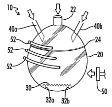
[0053] Fig. 1 is a side plan view of an apparatus for the production of
nano-scale catalyst particles utilizing a "closed system" reactor vessel in
accordance with the process of the present invention.
[0054] Fig. 2 is a side plan view of an alternate embodiment of the
apparatus of Fig. 1.
[0055] Fig. 3 is a side plan view of an apparatus for the production of
nano-scale catalyst particles utilizing a "flow-through" reactor vessel in
accordance with the process of the present invention.
[0056] Fig. 4 is an alternative embodiment of the apparatus of Fig. 3.
CA 02618806 2008-02-11
WO 2007/021769 PCT/US2006/031081
19
[0057] Fig. 5 is another alternative embodiment of the apparatus of
Fig. 3, using a collector external to the flow-through reactor vessel.
Best Mode For Carrying Out The Invention
[0058] Referring now to the drawings, an apparatus in which the
inventive process for the production of engineered nano-scale catalyst
particles can be practiced is generally designated by the numeral 10 or 100.
In Figs. 1 and 2 apparatus 10 is a closed system comprising closed reactor
vessel 20 whereas in Figs. 3-5 apparatus 100 is a flow-through reaction
apparatus comprising flow-through reactor vessel 120.
[0059] It will be noted that Figs. 1-5 show apparatus 10, 100 in a
certain orientation. However, it will be recognized that other orientations
are equally applicable for apparatus 10, 100. For instance, when under
vacuum, reactor vessel 20 can be in any orientation for effectiveness.
Likewise, in flow-through reactor vessel 120, the flow of inert carrier gas
and
decomposable moieties or the flow of decomposable moieties as drawn by a
vacuum in Figs. 3-5 can be in any particular direction or orientation and
still
be effective. In addition, the terms "up" "down" "right" and "left" as used
herein refer to the orientation of apparatus 10, 100 shown in Figs. 1-5.
[0060] Referring now to Figs. 1 and 2, as discussed above apparatus 10
comprises a closed-system reactor vessel 20 formed of any material suitable
for the purpose and capable of withstanding the exigent conditions for the
reaction to proceed inside including conditions of temperature and/or
pressure. Reactor vessel 20 includes an access port 22 for providing an inert
gas such as argon to fill the internal spaces of reactor vesse120, the inert
gas
being provided by a conventional pump or the like (not shown). Similarly, as
illustrated in Fig. 2, port 22 can be used to provide a vacuum in the internal
spaces of reactor vessel 20 by using a vacuum pump or similar device (not
shown). In order for the reaction to successfully proceed under vacuum in
reactor vessel 20, it is not necessary that an extreme vacuum condition be
created. Rather negative pressures no less than about 1 mm, preferably no
less than about 250 mm, are all that are required.
[0061] Reactor vessel 20 has disposed therein a support 30 which can
CA 02618806 2008-02-11
WO 2007/021769 PCT/US2006/031081
be attached directly to reactor vessel 20 or can be positioned on legs 32a and
32b within reactor vessel 20. Reactor vessel 20 also comprises a sealable
opening shown at 24, in order to permit reactor vessel 20 to be opened after
the reaction is completed to remove support 30. Closure 24 can be a
threaded closure or a pressure closure or other types of closing systems,
provided they are sufficiently air tight to maintain inert gas or the desired
level of vacuum within reactor vessel 20.
[0062] Apparatus 10 further comprises at least one feeder 40, and
preferably a plurality of feeders 40a and 40b, for feeding reactants, more
specifically the decomposable moiety, into reactor vessel 20. As illustrated
in
Figs. 1 and 2, two feeders 40a and 40b are provided, although it is
anticipated that other feeders can be employed depending on the nature of
the decomposable moiety/moieties introduced into vessel 20 and, especially,
on the end product nano-scale catalyst particles desired. Feeders 40a and
40b can be fed by suitable pumping apparatus for the decomposable moiety
such as venturi pumps or the like (not shown).
[0063] As illustrated in Fig. 1, apparatus 10 further comprises a source
of energy capable of causing decomposition of the decomposable moiety. In
the embodiment illustrated in Fig. 1, the source of energy comprises a source
of heat, such as a heat lamp 50, although other radiant heat sources can also
be employed. In addition, as discussed above, the source of energy can be a
source of electromagnetic energy, such as infrared, visible or ultraviolet
light,
microwave energy, radio waves or other forms of energy, as would be familiar
to the skilled artisan, provided the energy employed is capable of causing
decomposition of the decomposable moiety.
[0064] In one embodiment, the source of energy can provide energy
that is preferentially couple-able to support 30 so as to facilitate deposit
of
nano-scale catalyst particles produced by decomposition of the decomposable
moiety on support 30. However, where a source of energy such as heat is
employed, which would also heat reactor vessel 20, it may be desirable to cool
reactor vessel 20 using, e.g., cooling tubes 52 (shown partially broken away)
such that reactor vessel 20 is maintained at a temperature below the
CA 02618806 2008-02-11
WO 2007/021769 PCT/US2006/031081
21
decomposition temperature of the decomposable moiety. In this way, the
decomposable moiety does not decompose at the surfaces of reactor vesse120
but rather on support 30.
[0065] In an alternative embodiment illustrated in Fig. 2, support 30
itself comprises the source of energy for decomposition of the decomposable
moiety. For instance, a.resistance heater powered by connection 34 can be
incorporated into support 30 such that only support 30 is at the temperature
of decomposition of the decomposable moiety, such that the decomposable
moiety decomposes on support 30 and thus produces nano-scale catalyst
particles deposited on support 30. Likewise, other forms of energy for
decomposition of the decomposable moiety can be incorporated into support
30.
[0066] Support 30 can be formed of any material sufficient to have
deposit thereon of nano-scale catalyst particles produced by decomposition of
the decomposable moiety, such as the aluminum oxide or other components
of an automotive (or other internal combustion engine) catalytic converter, or
the electrode or membrane of a fuel cell or electrolysis cell. Indeed, where
the source of energy is itself embedded in or associated with support 30,
selective deposition of the catalytic nano-scale metal particles can be
obtained to increase the efficiency of the catalytic reaction and reduce
inefficiencies or wasted catalytic metal placement. In other words, the
source of energy can be embedded within support 30 in the desired pattern
for deposition of catalyst metal, such that deposition of the catalyst nano-
scale metal can be placed where catalytic reaction is desired. In one
embodiment, support 30 can be coated with an adhesive coating or a
fluoroelastomer, which may be used to impart alternative properties to
support 30. Alternatively, support 30 can be replaced by a collection device
for collection of the nano-scale metal particles produced, such as a cyclonic
or
centrifugal collector (not shown).
[0067] In another embodiment of the invention, as illustrated in Figs.
3-5, apparatus 100 comprises a flow-through reactor vessel 120 which
includes a port, denoted 122, for either providing an inert gas or drawing a
CA 02618806 2008-02-11
WO 2007/021769 PCT/US2006/031081
22
vacuum from reactor vessel 120 to thus create flow for the decomposable
moieties to be reacted to produce nano-scale catalyst particles. In addition,
apparatus 100 includes feeders 140a, 140b, 140c, which can be disposed
about the circumference of reactor vessel 102, as shown in Fig. 5, or, in the
alternative, sequentially along the length of reactor vessel 120, as shown in
Figs. 3 and 4.
[0068] Apparatus 100 also comprises support 130 on or in which nano-
scale catalyst particles are deposited. Support 130 can be positioned on legs
132a and 132b or, in the event a source of energy is incorporated into support
130, as a resistance heater, the control and wiring for the source of energy
in
support 130 can be provided through line 134, as illustrated in Fig. 4
Support 130 can be coated with an adhesive coating or a fluoroelastomer,
which may be used to impart alternative properties to support 130.
Alternatively, support 130 can be replaced by a collection device for
collection
of the nano-scale metal particles produced, such as a cyclonic or centrifugal
collector (not shown).
[0069] As illustrated in Figs. 3 and 4, when support 130 is disposed
within flow-through reactor vessel 120, a port 124 is also provided for
removal of support 130 with nano-scale catalyst particles deposited thereon.
In addition, port 124 should be structured such that it permits the inert gas
fed through port 122 and flowing through reactor vessel 120 to egress reactor
vessel 120 (as shown in Fig. 3). Port 124 can be sealed in the same manner
as closure 24 discussed above with respect to closed system apparatus 10. In
other words, port 124 can be sealed by a threaded closure or pressure closure
or other types of closing structures as would be familiar to the skilled
artisan.
[0070] As illustrated in Fig. 5, however, support 130 can be disposed
external to reactor vessel 120 in flow-through reactor apparatus 100. In this
embodiment, flow-through reactor vessel 120 comprises a port 124 through
which support 130 as nano-scale catalyst particles are deposited on support
130. In this way it is no longer necessary to gain access to reactor vessel
120
to remove support 130 having nano-scale catalyst particles deposited
CA 02618806 2008-02-11
WO 2007/021769 PCT/US2006/031081
23
thereon. In addition, during the impingement of the decomposable moieties
to form nano-scale catalyst particles on support 130, either port 126 or
support 130 can be adjusted in order to provide for an impingement to
produced nano-scale catalyst particles on certain specific areas of support
130. This is especially useful in the circumstances where support 130
comprises the end use substrate for the nano-scale catalyst particles such as
the component of a catalytic converter or electrode for fuel cells. Thus, the
nano-scale catalyst particles are only deposited where desired and efficiency
and decrease of wasted catalytic metal is facilitated.
[0071] As discussed above, reactor vessel 20, 120 can be formed of any
suitable material for use in the reaction provided it can withstand the
temperature and/or pressure at which decomposition of the decomposable
moiety occurs. For instance, the reactor vessel should be able to withstand
temperatures up to about 250 C where heat is the energy used to decompose
the decomposable moiety. Although many materials are anticipated as being
suitable, including metals, plastics, ceramics and materials such as graphite,
preferably reactor vessels 20, 120 are formed of a transparent material to
provide for observation of the reaction as it is proceeding. Thus, reactor
vessel 20, 120 is preferably formed of quartz or a glass such as Pyrex brand
material available from Corning, Inc. of Corning, New York.
[0072] In the practice of the invention, either a flow of an inert gas
such as argon or a vacuum is drawn on reactor vessel 20, 120 and a stream of
decomposable moieties is fed into reactor vessel 20, 120 via feeders 40a, 40b,
140a, 140b, 140c, wherein at least one of the nature of the decomposable
moiety introduced into the reactor vessel through each feeder, the rate of
feeding of each decomposable moiety, and the order in which different species
are fed into the reactor vessel is controlled. The decomposable moieties can
be any metal containing moiety such as an organometallic compound, a
complex or a coordination compound, such as a metal carbonyl, which can be
decomposed by energy at the desired decomposition conditions of pressure
and temperature. For instance, if heat is the source of energy the
decomposable moiety should be subject to decomposition and production of
CA 02618806 2008-02-11
WO 2007/021769 PCT/US2006/031081
24
nano-scale metal particles at temperatures no greater than 250 C, more
preferably no greater than 200 C. Other materials, such as oxygen, can also
be fed into reactor 20, 120 to partially oxidize the nano-scale metal
particles
produced by decomposition of the decomposable moiety, to protect the nano-
scale particles from degradation. Contrariwise, a reducing material such as
hydrogen can be fed into reactor 20, 120 to moderate or reduce oxidation of
the nano-scale catalyst particles.
[0073] The energy for decomposition of the decomposable moiety is
then provided to the decomposable moiety within reactor vessel 20, 120 by,
for instance, heat lamp 50, 150. If desired, reactor vessel 120 can also be
cooled by cooling coils 52, 152 to avoid deposit of nano-scale catalyst
particles
on the surface of reactor vessel 20, 120 as opposed to support 30, 130. Nano-
scale catalyst particles produced by the decomposition of the decomposable
moieties are then deposited on support 30, 130 for use.
[0074] Thus the present invention provides a facile means for
producing nano-scale catalyst particles which have a high percentage of
principal particles, and, indeed, which have a predetermined orientation,
without the need for extremes of temperature and pressure required by prior
art processes. In addition, when a "flow-through" apparatus is used the
process is also continuous, providing desired economies of scale.
[0075] All cited patents, patent applications and publications referred
to herein are incorporated by reference.
[0076] The invention thus being described, it will be apparent that it
can be varied in many ways. Such variations are not to be regarded as a
departure from the spirit and scope of the present invention and all such
modifications as would be apparent to one skilled in the art are intended to
be included within the scope of the following claims.