Note: Descriptions are shown in the official language in which they were submitted.
CA 02618874 2008-01-23
"Blowout Preventer having Modified Hydraulic Operator"
FIELD OF THE INVENTION
The present invention relates to blowout preventers used in the oil and
gas industry. More specifically, the present invention relates to
hydraulically
operated blowout preventers.
BACKGROUND OF THE INVENTION
Blowout preventers (BOPs) are large valves that encase wellbore
piping at ground surface. One form of BOP is a ram-type BOP, which typically
comprises two horizontally opposed "ram" assemblies having ram blocks that
sealingly engage with each other at the center of the wellbore, or around a
tubular element in the wellbore, to prevent fluid flow therethrough.
Over time, the ram blocks must be replaced due to wear and tear, or to
change their size to accommodate varying sizes of pipe. Accordingly, ram-
type BOPs require means for accessing the ram blocks without having to
remove the entire BOP from the wellhead. Ram access doors or "bonnets",
connected to the ram assemblies are provided. These doors, which are
capable of opening to allow servicing or replacement of the ram blocks, are
commonly provided on each side of the BOP. Due to the size and weight of
the doors, hydraulic operators are commonly used to control opening and
closing of the doors, thereby easing access to the ram blocks.
It is known in the industry to mount the access doors on a hinge pin
such that the doors swing between an open and a closed position. Commonly,
CA 02618874 2008-01-23
hinged-door BOPs are configured so that hydraulic fluid passageways extend
through a bore drilled through the hinge pin, or through a hinge bracket.
However, due to the intricacy of the fluid passageways, perfect alignment
between the pin or bracket and the door must occur or leakage may result.
The requirement for extremely precise and accurate positioning of various
parts makes the hinged-door BOP prone to early failure and difficult to repair
and/or maintain.
In order to address these difficulties with hinged doors, they have been
mounted upon shafts or "slide studs" extending outwardly from the body of the
BOP. For instance, the Type "U" Blowout Preventer manufactured by
Cameron Iron Works, Inc. (Houston, Texas, U.S.A.), provides doors which are
hydraulically manoeuvred along shafts towards and away from the BOP. In
order to operate door movement, the Cameron BOP system has two separate
and distinct hydraulic operators per door; one for opening the doors and one
for closing the doors. The need for two hydraulic cylinders per door adds
considerable weight, size and complexity to the overall configuration of the
BOP.
Ram-type BOPs comprising a single, dual-acting (i.e. capable of
opening and closing) hydraulic operator for each door are also known. For
instance, Canadian Patent No. 2,506,828, filed 29 April 2005 (the '828
application) by Dean Foote and Scott Delbridge, describes such a ram-type
BOP. The assembly disclosed in the '828 application, however, is known to be
somewhat difficult to assemble and prone to damage, thereby resulting in
2
CA 02618874 2008-01-23
costs due to the requirement for providing exacting tolerances on some
components.
Having reference to prior art Figures 1 to 5, one such component is the
adapter "A" which forms part of the hydraulic operator. The adapter A, as
configured in the '828 patent, involves certain features which are
problematic,
more particularly:
= the adapter "A" forms hydraulic fluid channels "F" and is threadably
engaged with the piston sleeve "PS" component of the hydraulic
operator "0". This engagement requires that the adapter "A" be
significant in length to accommodate threading interface "T" (see
Figures 2 and 3), and may result in damage to 0-ring-type seals "S"
around the adapter during installation;
= second, the adapter "A" must be secured in place within the
hydraulic operator "0" by a plurality of cap screws "C". Each cap
screw "C", sealed by its own 0-ring, presents a potential "leakage
point" of hydraulic fluid from the adapter to the exterior of the BOP;
and
= third, a number of 0-ring-type seals "OS" around the adapter "A"
and the cap screws "C" are unreliable and are subject to wear and
tear requiring constant maintenance and upkeep.
Accordingly, the complexity of the prior art adapter arrangement disclosed in
the '828 application causes maintenance to be challenging and costly, and
results in a significant number of "leakage points" for system failure (due to
leakage of hydraulic fluid).
3
CA 02618874 2008-01-23
There is therefore a need in the industry for a ram-type BOP
comprising a single, dual-acting hydraulic operator for each door that is
lighter, more compact and not susceptible to system failure as a result of
fluid
leakage.
SUMMARY OF THE INVENTION
A blowout preventer (BOP), having modified hydraulic operators, is
described. The ram-type BOP disclosed herein is known and comprises a
single, dual-acting, telescoping hydraulic operator for controlling the
opening
and closing of each door assembly. The operator has been modified to
provide a reconfigured adapter for increased reliability and ease of
manufacturing.
The reconfigured adapter generally comprises a body having a
longitudinal bore and forming a plurality of hydraulic fluid passageways
therethrough. The adapter is slidably received within the door assembly of
the BOP and abutted in position by the operator, which is threadably secured
to the door assembly. A threaded engagement between the operator and the
door assembly may result in a more stable and secure anchor point from
which the operator may telescope. Further, the threaded connection may
result in the reduction of pressure boundaries and may provide means for
obtaining a self-contained hydraulic pressure system.
It is an object of the present invention to provide an adapter that is
slidably received and retained by the door assembly of the BOP, thereby
4
CA 02618874 2008-01-23
eliminating the need for a threaded engagement between the adapter and the
BOP.
It is a further object of the present invention to provide a modified
adapter that is slidably received and retained by the door assembly of the
BOP and abutted into position by the hydraulic operator, thereby eliminating
the need for cap screws and their associated o-ring seals and providing a
solid anchor point that is internal to the hydraulic pressure system.
DESCRIPTION OF THE DRAWINGS
Figure 1 (prior art) is a longitudinal cross section of a door assembly
forming part of a ram-type BOP having an adapter threadably engaged to the
piston sleeve of a hydraulic operator.
Figure 2 (prior art) is an amplified cross sectional view of the adapter of
Figure 1 threadably engaged with the operator's piston sleeve.
Figure 3 (prior art) is an elevational side view of the adapter of Figure
1.
Figure 4 (prior art) is a perspective view of the adapter of Figure 1.
Figure 5 (prior art) is a top plan view of the adapter of Figure 1.
Figure 6 is a side view of a BOP, as described herein, having a body
and two door assemblies, showing a cross-section of the BOP body to expose
the horizontal and vertical passageways therewithin.
Figure 7 is an end view of the BOP shown in Figure 6.
Figure 8 is a longitudinal cross-sectional view of one door assembly
and operator of the BOP, shown in Figure 6, with the door assembly closed
5
CA 02618874 2008-01-23
and locked against the BOP body and the ram assembly in the "open"
position.
Figure 9 is a longitudinal cross-sectional of the door assembly and
operator shown in Figure 8 with movement, as shown by directional arrows, of
the ram assembly towards a closed position.
Figure 10 is a longitudinal cross-sectional view of the door assembly
and operator with the door assembly unlocked and the operator telescoping
away from the BOP body (see directional arrows).
Figure 11 is a longitudinal cross-sectional view of the door assembly
and operator, as shown in Figure 10, as they continue to telescope away from
the BOP body, having arrows within the operator and the door assembly
depicting hydraulic fluid flow therethrough.
Figure 12 is a longitudinal cross-sectional view of the door assembly
and operator, shown in Figures 10 and 11, with the door assembly and the
operator fully telescoped to the open position, and the ram block being
removed.
Figure 13 is a longitudinal cross-sectional view of the door assembly
and operator showing the door assembly and the operator retracting towards
the closed position against the BOP body (see directional arrows).
Figure 14 is a longitudinal cross-sectional view of the door assembly
and operator as they telescopically retract towards the body of the BOP
having arrows depicting hydraulic fluid flow therethrough.
Figure 15 is a side elevational view of the adapter as described herein.
Figure 16 is a sectional side view of the adapter shown in Figure 15.
6
CA 02618874 2008-01-23
DESCRIPTION OF THE EMBODIMENTS
By way of background, a ram-type blowout preventer (BOP) having a
single, dual-acting hydraulic operator will now be described with reference to
Figures 6 - 16.
Ram-type Blowout Preventer
The body of the BOP 10 forms two longitudinal and intersecting
passageways (as seen in Figure 6). A first vertical passageway 12 is aligned
with the wellbore and forms a conduit for piping and fluid flow from the
wellbore. A second, horizontal passageway, intersects vertical passageway
12, to form two bilaterally opposed ram receiving passages 14, each having
an opening 13 at the terminal or distal end.
A pair of closures, or door assemblies 20, for "sealing or "closing"
opening 13, are positioned adjacent to the distal ends of the ram receiving
passage 14. Each door assembly 20 is slidably mounted upon a pair of slide
studs 18, protruding from and integral to the BOP body 10. In order to "lock"
the door assemblies in sealing engagement with the BOP body 10, and
thereby prevent blowouts of the wellbore, movement of door assemblies 20
along slide studs 18 is prevented. For instance, stud nuts 17 may be
threaded along the slide studs 18 to lock the door assemblies 20 in place (see
Figures 7 and 8). In order to "unlock" the doors, the stud nuts 17 may be
disengaged (see Figures 10 and 11).
For ease of reference, the term "proximal(ly)" herein refers to elements
positioned closer, or towards, the BOP body 10, and the term "distal(Iy)"
shall
refer to elements farther away from the BOP body 10.
7
CA 02618874 2008-01-23
Having regard to Figure 8, each door assembly 20 comprises an
interior longitudinally extending bore, referred to as the ram passageway 23,
and a hydraulic fluid cylinder 33, which is aligned with and distal to the ram
passageway 23. The following elements are associated with the ram
passageway 23 and hydraulic cylinder 33 of the door assembly 20 and form
one reciprocating unit:
^ a hydraulic piston 26, positioned within the hydraulic cylinder 33,
wherein the hydraulic piston 26 and the hydraulic cylinder 33 form:
o a first fluid ram chamber 25 (see Figure 9), distally adjacent
to the piston 26; and
o a second fluid ram chamber 27 (see Figure 4), proximally
adjacent to the piston 26;
^ a piston shaft 24, reciprocally actuated within the hydraulic cylinder 33
by the hydraulic piston 26;
^ a ram shaft 28, connected with the piston shaft 24 and positioned
within the ram passageway 23. Reciprocal movement of the piston 26
biases the ram shaft 28 inwardly and the piston shaft 24 outwardly from
the BOP body 10; and
^ a ram block 30, releasably secured to the ram shaft 28 at its proximal
end.
When door assemblies 20 are closed against BOP body 10, the
opening 13 formed by the BOP body 10 is aligned with the ram passageway
23 and the hydraulic cylinder 33. Movement of the piston 26 (see arrows 55 in
Figure 9), within hydraulic cylinder 33, results in the simultaneous movement
8
CA 02618874 2008-01-23
of piston shaft 24, ram shaft 28 and ram block 30. For ease of reference, the
assembly comprising piston shaft 24, piston 26, ram shaft 28 and ram block
30 shall hereinafter be referred to as the ram assembly 40. It should be
understood that the ram assembly 40 need not comprise three distinct
elements as herein described, but may be configured from one or any number
of separate components or parts. When the BOP is engaged, each opposed
ram assembly 40 extends inwardly through opening 13 into ram receiving
passageway 14 until the two assemblies meet within vertical passageway 12,
thereby closing the wellbore and blocking fluid flow therethrough.
Hydraulic Operators
By way of further background, one single (or double-acting),
telescoping hydraulic operator 50 may actuate each of:
= longitudinal reciprocation of the ram assemblies 40 between an
open and closed position; and,
= longitudinal movement of the door assemblies 20 along slide studs
18, thereby opening and/or closing the BOP.
Having regard to Figures 11 and 12, a telescoping hydraulic operator
50, comprising a system of interconnected cylindrical tubes is provided. The
hydraulic operator 50 comprises :
= a first dual-cylinder assembly 60 (see Figure 12) having a proximal
first end, associated with the BOP body 10, and a distal second
end, and dual-cylinder assembly 60 comprises:
o a body anchor tube 62, forming a first fluid passageway 100,
sealingly connected at its first end to the BOP body 10 and
9
CA 02618874 2008-01-23
aligned to receive hydraulic fluid from the fluid inlet P1 (see
Figure 11); and
o a piston sleeve 64, sllidably inserted over the second end of
the body anchor tube 62, which forms a second fluid
passageway 200 therebetween, having its first end sealably
engaged with the BOP body 10 and aligned to receive
hydraulic fluid from the fluid inlet P2 (see Figure 14);
wherein the piston sleeve 64 is retained in position against the BOP
body 10 by an operator piston 66, which abuts the second end of
the piston sleeve 64 and is threadably engaged with the second
end of the body anchor tube 62. It should be understood that the
connection between the operator piston 66 and the first dual-
cylinder assembly may be an equivalent form of sealable
connection.
The first dual-cylinder assembly 60 is telescopically connected with:
= a second dual-cylinder assembly 80 having a first proximal end,
associated with the door assembly 20, and a second distal end,
comprising:
o a piston cylinder 82, having its first proximal end recessed
within and threadably engaged to door assembly 20, thereby
providing positive retention for the operator 50 or an anchor
point from which the operator may telescope;
o a cylinder housing 84, slidably inserted over the second end
of the piston cylinder 82, which forms a third fluid
CA 02618874 2008-01-23
passageway 300 therebetween that is continuous with first
the fluid passageway 100, the cyiinder housing 84 being
engaged, at its first end, with the door assembly 20;
o a cylinder retainer 86, for adjoining piston cylinder 82 and
cylinder housing 84, so that the cylinder retainer 86 abuts the
second end of the cylinder housing 84 and retains the
cylinder housing 84 in position against the door assembly 20,
the retainer 86 being threadably engaged with piston cylinder
82; and
wherein the first dual-cylinder assembly 60 is telescopically connected,
through an adapter 70 (see Figures 13 and 14) slidably recessed within
door assembly 20, to the second dual-cylinder assembly 80.
Telescopic hydraulic operator 50 further comprises two fluid receiving
chambers formed within piston cylinder 82. More particularly, a first operator
fluid chamber 65 is distally adjacent to operator piston 66, and a second
operator fluid chamber 67 is proximally adjacent to operator piston 66.
Second chamber 67 forms a fourth fluid passageway 400 that is continuous
with the second fluid passageway 200.
Having regard to Figures 11 and 14, directional arrows depict the
hydraulic fluid flow as the door assembly is opened (Fig. 11) and closed (Fig.
14). Fluid flow is described in more detail below.
The Adapter
i~
CA 02618874 2008-01-23
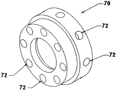
An adapter 70 is used to provide a hydraulic fluid interface between
fluid flowing through operator 50 and door assembly 20. It further serves as a
flow resistor within the operator 50.
The adapter 70 is slidably recessed within door assembly 20. The first
proximal end of the piston cylinder 82, which is sealingly or threadably
engaged with door assembly 20, abuts adapter 70, thereby retaining adapter
70 in place. Fluid passageways 72 formed in adapter 70 provide fluid
communication conduits between fluid chamber 67 and fourth fluid
passageway 400 in the operator 50 and fluid ram chamber 27 in door
assembly 20. A seal 74 for retaining hydraulic fluid within the adapter 70 is
positioned between the adapter 70 and the door assembly 20. The seal 70
preferably comprises a seal designed for reciprocal movement. For example a
PolyPakT"" seal (Parker Seals, Utah, U.S.A.) may be used to prevent fluid
leakage from within the operator 50 to the exterior of door assembly 20.
The adapter 70 is configured shorter in length than the known adapter
A shown in prior art Figure 1 as the need for a threading interface T is
eliminated. The adapter 70 is configured without cap-screw receiving ports, as
the need to secure it in place with cap screws and their associated low-
reliability 0-ring seals is eliminated.
Operation
Opening and Closing ram blocks 30 (Doors Locked):
Having regard to Figures 8 and 9, when stud nuts 17 are engaged and
door assemblies 20 are "locked" to the BOP body, fluid may be introduced
through inlet port P1 to bias the ram assembly 40 into a "closed" position
12
CA 02618874 2008-01-23
(arrows 55). Hydraulic fluid introduced through inlet port P1 flows along the
interior passageway 100 of the body anchor 62 and the operator piston 66
into distal operator fluid chamber 65 (see fluid arrows in Figure 11). As
pressure in fluid chamber 65 increases, fluid will flow along the fluid
passageway 300 formed between piston cylinder 82 and cylinder housing 84
into distal ram chamber 25 (see fluid arrows in Figure 11). As fluid pressure
increases in ram chamber 25, ram assembly 40 is biased inwardly towards
BOP body 10. The opposed ram assemblies 40 travel along ram passageway
23 into ram receiving passageways 14 and sealingly engage each other within
the wellbore, thereby "closing" the BOP and preventing blowouts.
To open the ram blocks 30, the flow of hydraulic fluid may be reversed
by introducing the fluid into inlet port P2. Fluid will flow along the
passageway
200 formed between body anchor cylinder 62 and piston sleeve 64 into
proximal operator fluid chamber 67 and fourth fluid passageway 400 (see
Figure 14). Fluid leaves the fluid chamber 67 of the operator 50 through
adapter 70 and enters proximal fluid ram chamber 27. This causes outward
longitudinal movement of piston 26 and the entire ram assembly 40 (arrow
57). As ram assembly 40 moves outwardly, ram blocks 30 are disengaged
and drawn back through ram receiving passageways 14 into door assemblies
20, thereby "opening" the BOP.
Door Assemblies 20
When stud nuts 17 are disengaged from BOP body 10, the door
assemblies 20 may be opened and closed, thereby allowing access to the
ram blocks 30 (see Figures 10 - 13).
13
CA 02618874 2008-01-23
Opening Door Assemblies 20
In order to open door assemblies 20, hydraulic fluid may be introduced
into fluid inlet port P1 and into distal ram chamber 25 (see Figure 11). As
fluid
pressure increases in chamber 25, ram assembly 40 is biased inwardly
towards BOP body 10. As the ram assembly 40 travels inwardly, fluid
pressure in chamber 65 increases, resulting in operator 50 telescoping away
from BOP body 10 along slide studs 18. As a result, the entire door assembly
20 progresses outwardly along slide studs 18 (see Figure 10). As the second
dual-cylinder assembly 80 becomes fully extended, the ram assembly 40 is
simultaneously extended inwardly toward BOP body, thereby moving the ram
blocks 30 into the gap formed between the door assembly 20 and BOP body
10.
Closinp Door Assemblies 20
To close the door assemblies 20, hydraulic fluid may be introduced into
inlet port P2, whereby it flows into proximal operator fluid chamber 67 (see
Figure 14). As pressure in chamber 67 increases, the second dual-cylinder
assembly 80 and the entire door assembly 20 travel inwardly toward the BOP
body 10, until the door assembly 20 engages the BOP body 10. Stud nuts 17
may then be threadably engaged with the BOP body 10.
Once door assembly 20 is secured in place, ram assembly 40 may
closed as described above.
14