Note: Descriptions are shown in the official language in which they were submitted.
CA 02619665 2008-02-18
Specification
ROD TYPE IONTOPHORESIS DEVICE
Technical Field
[0001]
The present invention relates to a rod-type iontophoresis
device for administering a drug ion to an organism.
Background Art
[0002]
Such iontophoresis device as described above is intended for
permeating a drug solution into a skin or a mucous membrane, and
has been conventionally used for a skin or mucous membrane having
a relatively wide area of at least about 20 mm in diameter.
[0003]
On the other hand, in the case of, for example, the
therapy/ treatment in an oral cavity such as the therapy ofstomatitis,
local anesthesia in an oral cavity, or local anesthesia in
odontotherapy, or the therapy of an integument such as melanoma
or skin cancer, the direct injection of a drug solution into an
affected area as a part (pinpoint) of an organism may increase a
therapeutic effect.
[0004]
In such case, one prefers iontophoresis to injection for
permeating a drug solution because the iontophoresis is
non-invasive.
1
CA 02619665 2008-02-18
TCF006CA
[0005]
Upon photodynamic therapy (PDT), a photosensitized reactive
material is administered and irradiatedwith light,and an anticancer
action is expected from the irradiation. However, a patient must
be prevented from being irradiated with sunlight because the
sensitizer circulates in hisorher body. In addition,thesensitizer
may circulate in a portion except an affected area to provide a
side effect. Therefore, PDT has demanded the administration of a
sensitizer only to an affected area.
Disclosure of the Invention
[ 0006]
An object of the present invention is to provide an
iontophoresis device suitably used for permeating a drug solution
into a part of an organism that can be observed by a doctor from
the outside in, for example, local anesthesia in an oral cavity
or the therapy of melanoma.
[0007]
The above object can be achieved by the following various
examples.
[0008]
(1) A rod-type iontophoresis device including: a working side
electrode assembly and a non-working side electrode assembly each
used for administering an ionic drug by iontophoresis; and a DC
electric power source connected to the working electrode assembly
2
CA 02619665 2008-02-18
TCF006CA
and the non-working side electrode as semblywith opposite polarities,
characterized by including: a rod-like member for supporting the
working side electrode assembly and the non-working side electrode
assembly; and a bar-like holding portion for detachably supporting
the rod-like member, the working side electrode assembly and the
non-working side electrode assembly being placed at the tip of the
rod-like member,andapredetermined amount of spacing being provided
between the working electrode assembly and the non-working electrode
assembly.
[0009]
(2) The rod-type iontophoresis device according to the above
item (1) , characterized in that the ionic drug is a photosensitized
reactive material to be activated by absorbing light, and the holding
portion has an irradiation optical system for applying light from
the vicinity of the tip of the working side electrode assembly.
[0010]
(3) The rod-type iontophoresis device according to the above
item (2), characterized in that the holding portion includes: a
light source composed of a light-emitting diode or a laser diode
for emittinglighthaving a wavelength sensed by the photosensiti zed
reactive material; and an optical fiber for irradiation for
introducing light emitted from the light source to the rod-like
member or a neighborhood thereof.
[0011]
3
CA 02619665 2008-02-18
TCF006CA
(4) The rod-type iontophoresis'device according to any one
of the above items (1) to (3), characterized in that: the holding
portion has an electric power source side working electrode terminal
and an electric power source side non-working electrode terminal
connected to the DC electric power source with opposite polarities
through wiring from the DC electric power source, the wiring being
housed in the holding portion; the rod-like member has on a proximal
end of a side thereof detachable from the holding portion a working
side electrode terminal and a non-working side electrode terminal
which are connected to or are separated from the electric power
source side working electrode terminal and the electric power source
side non-working electrode terminal when attached to or detached
from the holding portion; and the working side electrode teriminal
and the non-working side electrode terminal are connected to a working
side electrode and a non-working side electrode in the working side
electrode assembly and the non-working side electrode assembly,
respectively.
[0012]
(5) The rod-type iontophoresis device according to the above
item (4), characterized in that a controller is provided in the
holding portion, the controller being placed in an electric power
source circuit between the electric power source side working
electrode terminal and the electric power source side non-working
electrode terminal and the DC electric power source for adjusting,
4
CA 02619665 2008-02-18
TCF006CA
out of a current value during energization and an energization time
as administration time, at least the current value.
[0013]
(6) The rod-type iontophoresis device according to any one
of the above items (1) to (5), characterized in that the working
side electrode assembly and the non-working side electrode assembly
are placed such that central axes thereof are in parallel with each
other.
[0014]
(7) The rod-type iontophoresis device according to any one
of the above items (1) to (5), characterized in that the working
side electrode assembly and the non-working side electrode assembly
are placed such that central axes thereof spread out to a tip
direction.
[0015]
(8) The rod-type iontophoresis device according to any one
of the above items (1) to (5), characterized in that the working
side electrode assembly and the non-working side electrode assembly
are placed such that central axes thereof intersect each other in
a tip direction.
[0016]
(9) The rod-type iontophoresis device according to any one
of the above items (1) to (8), characterized in that: the working
side electrode assembly includes: the working side electrode
5
CA 02619665 2008-02-18
TCF006CA
connected to the DC electric power source having the same polarity
as that of a charged ion of the ionic drug; an electrolyte solution
holding portion holding an electrolyte solution, the electrolyte
solution holding portion being placed on the front surface of the
working side electrode; a second ion exchange membrane selecting
an ion having a polarity opposite to that of the charged ion of
the ionic drug, the second ion exchange membrane being placed on
the front surface of the electrolyte solution holding portion; a
drug solution holding portion holding the ionic drug, the drug
solution holding portion being placed on the front surface of the
second ion exchange membrane; and a first ion exchange membrane
which is the ion exchange membrane selecting an ion having the same
polarity as that of the charged ion of the ionic drug, the first
ion exchange membrane being placed on the front surface of the drug
solution holding portion; and the non-working side electrode
assembly includes: the non-working side electrode connected to the
DC electric power source having a polarity opposite to that of the
charged ion of the ionic drug; a second electrolyte solution holding
portion holding a second electrolyte solution, the second
electrolyte solution holding portion being placed on the front
surface of the non-working side electrode; a third ion exchange
membrane selecting an ion having the same polarity as that of the
charged ion of the ionic drug, the third ion exchange membrane being
placed onthefrontsurfaceofthesecondelectrolytesolution holding
6
CA 02619665 2008-02-18
TCF006CA
portion; a third electrolyte solution holding portion holding a
third electrolyte solution, the third electrolyte solution holding
portion being placed on the front surface of the third ion exchange
membrane; and a fourth ion exchange membrane which is the ion exchange
membrane selecting an ion having a polarity opposite to that of
the charged ion of the ionic drug, the fourth ion exchange membrane
being placed on the front surface of the third electrolyte solution
holding portion.
Brief Description of the Drawings
[0017]
[ Fig . 1] Aplan view showing an iontophoresis device according
to an embodiment of the present invention.
[Fig. 2] An enlarged sectional view taken along the line II-II
of Fig. 1.
[Fig. 3] An enlarged sectional view showing a main portion
of each of a working side electrode assembly and a non-working side
electrode assembly.
[Fig. 4] A plan view showing another placement example of the
working side electrode assembly and the non-working side electrode
assembly.
[Fig. 5] A plan view showing still another placement example
of the working side electrode assembly and the non-working side
electrode assembly.
[Fig. 6] An enlarged front view showing a main portion of a
7
CA 02619665 2008-02-18
TCF006CA
rod-type iontophoresis device according to Example 2 of the present
invention.
[Fig. 7] A left side view of the rod-type iontophoresis device.
Best Mode for carrying out the Invention
[0018]
Hereinafter, the best mode for carrying out the present
invention will be described in detail with reference to the drawings.
[0019]
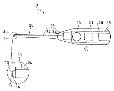
As shown in Figs. 1 and 2, a rod-type iontophoresis device
10 according to the best mode is constituted by a working side
electrode assembly 12 and a non-working side electrode assembly
14 each used for administering an ionic drug, a rod-like member
16 for integrally supporting them, and a DC electric power source
18 connected to the working side electrode assembly 12 and the
non-working side electrode assembly 14 with opposite polarities.
[0020]
The working side electrode assembly 12 and the non-working
side electrode assembly 14 are attached to the tip of the rod-like
member 16, and the rod-like member 16 is detachably supported by
the tip of a bar-like holding portion 20. As a result, the working
side electrode assembly 12 and the non-working side electrode
assembly 14 are exchangeable integrally with the rod-like member
16. A proximal end portion of the holding portion 20 opposite to
the rod-like member 16 serves as a gripping portion 21 having a
8
CA 02619665 2008-02-18
TCF006CA
diameter large enough to be gripped by a human hand.
[0021]
The holding portion 20 has an irradiation optical system 26
including: an irradiation light source 22 composed of a
light-emittingdiode (LED) or a laserdiodepresent inside the system;
and an optical fiber 24 for irradiation for introducing light emitted
from the irradiation light source 22 to a neighborhood of the rod-like
member 16. As shown in Fig. 2, the optical fiber 24 for irradiation
is placed such that a tip thereof is adjacent to the rod-like member
16, and is adapted to emit, from the tip, irradiation light with
which an affected area or the like of an organism at a position
with which the working side electrode assembly 12 can contact is
irradiated.
[0022]
The working side electrode assembly 12 and the non-working
side electrode assembly 14 are connected to different polarities
of the DC electric power source 18 through an electric power source
circuit 28. The irradiation light source 22 is also connected to
the DC electric power source 18 through a switch 23.
[0023]
An end portion of the rod-like member 16 on the side of the
holding portion 20 is provided with a working side electrode terminal
32 to be connected to the working side electrode assembly 12 and
a non-working side electrode terminal 34 to be connected to the
9
CA 02619665 2008-02-18
TCF006CA
non-working side electrode assembly 14.
[0024]
Theworking electrode terminal 32 and the non-working electrode
terminal 34 are adapted to be connected to an electric power source
side working electrode terminal 33 and an electric power source
side non-working electrode terminal 35 on the side of the holding
portion 20, respectively, when the rod-like member 16 is attached
to the holding portion 20.
[0025]
The electric power source side working electrode terminal 33
and the electric power source side non-working electrode terminal
35 are further connected to the DC electric power source 30 placed
outside through the electric power source circuit 28.
[0026]
The rod-like member 16 is a cylindrical member having a diameter
smaller than that of the tip of the holding portion 20, and is adapted
to be capable of: being attached by being threaded with a male screw
portion 16A into a female screw portion 20A at the tip of the holding
portion 20; and being detached by being rotated in the opposite
direction.
[0027]
Fig. 3 is an enlarged view showing that the working side
electrode assembly 12 and the non-working side electrode assembly
14 are placed such that central axes thereof are in parallel with
CA 02619665 2008-02-18
TCF006CA
each other. In addition, the working side electrode assembly 12
is constituted by laminating a working side electrode 36, an
electrolyte solution holding portion 38, a second ion exchange
membrane 40, a drug solution holding portion 42, and a first ion
exchange membrane 44 in this order from the side of the rod-like
member 16, and is formed into a disk shape of about 2 to 6 mm in
diameter.
[0028]
The working side electrode 36 is desirably constituted by a
conductive paint applied to one surface of a base sheet 13 and blended
with a nonmetal conductive filler such as a carbon paste. Theworking
side electrode 36 can be constituted by a copper plate or a metal
thin film, but a metal eluted from the plate or the thin film may
transfer to an organism upon administration of a drug. Therefore,
the working side electrode 36 is preferably nonmetallic.
[0029]
The electrolyte solution holding portion 38 is constituted
by, for example, an electrolytic paint applied to the working side
electrode 36. The electrolytic paint is a paint containing an
electrolyte, and an electrolyte that is oxidized or reduced more
easily than the electrolytic reaction of water (oxidation on a
positive pole and reduction on a negative pole) is particularly
preferably used. Examples of such electrolyte include: medical
agents such as ascorbic acid (vitamin C) and sodium ascorbate; and
11
CA 02619665 2008-02-18
TCF006CA
organic acids such as lactic acid, oxalic acid, malic acid, succinic
acid, and fumaric acid and/or salts thereof. The use of such
electrolyte can suppress the generation of an oxygen gas or a hydrogen
gas. In addition, blending multiple kinds of electrolytes serving
as a combination of buffer electrolyte solutions when dissolved
in a solvent can suppress a change in pH during energization.
[0030]
The electrolytic paint is blended with a hydrophilic polymer
such as polyvinyl alcohol, polyacrylic acid, polyacrylamide, or
polyethylene glycol in order to improve the application property
and film-forming property of the paint, and is blended with an
appropriate amount of solvent such as water, ethanol, or propanol
for adjusting the viscosity of the electrolytic paint. The paint
may be blended with an appropriate additional component such as
a thickener, a thixotropic agent, a defoaming agent, a pigment,
a flavor, or a coloring agent.
[0031]
The second ion exchange membrane 40 is formed by applying a
second ion exchange paint to the electrolyte solution holding portion
38.
[0032]
The second ion exchange paint is a paint containing an ion
exchange resin into which an ion exchange group using, as a counter
ion, an ion having a conductivity type opposite to that of a drug
12
CA 02619665 2008-02-18
TCF006CA
ion in the drug solution holding portion 42 to be described later
is introduced. In the case where a drug whose drug component
dissociates to plus drug ions is used in the drug solution holding
portion 42, the paint is blended with an anion exchange resin. On
the other hand, in the case where a drug whose drug component
dissociates to minus drug ions is used, the paint is blended with
a cation exchange resin.
[0033]
The drug solution holding portion 42 is composed of a drug
paint applied to the second ion exchange membrane 40. The paint
is a paint containing a drug (including a precursor for the drug)
whose drug component dissociates to plus or minus ions (drug ions)
as a result of, for example, dissolution into a solvent such as
water. Examples of a drug whose drug component dissociates to plus
ions include lidocaine hydrochloride as an anesthetic drug and
morphine hydrochloride as an anesthetic drug. Examples of a drug
whose drug component dissociates to minus ions include ascorbic
acid as a vitamin agent.
[0034]
The first ion exchange membrane 44 is formed of a first ion
exchange paint applied to the drug solution holding portion 42.
The first ion exchange paint is a paint containing an ion exchange
resin into which an ion exchange group using, as a counter ion,
an ion having the same conductivity type as that of the drug ion
13
CA 02619665 2008-02-18
TCF006CA
in the drug solution holding portion 42 is introduced. In the case
where a drug whose drug component dissociates to plus/minus drug
ions is used in the drug solution holding portion 42, the paint
is blended with an anion/cation exchange resin.
[0035]
An ionexchange resin obtained by introducing a cation exchange
group (an exchange group using a cation as a counter ion) such as
a sulfonic group, a carboxylic group, or a phosphoric group into
a polymer having a three-dimensional network structure such as a
hydrocarbon-based resin (for example, a polystyrene resin or an
acrylic resin) or a fluorine-based resin having a perfluorocarbon
skeleton can be used as the cation exchange resin without any
limitation.
[0036]
Anion exchangeresin obtained byintroducing an anionexchange
group (an exchange group using an anion as a counter ion) such as
a primary amino group, a secondary amino group, a tertiary amino
group, a quaternary ammonium group, a pyridyl group, an imidazole
group, a quaternary pyridinium group, or a quaternary imidazolium
group into a polymer having a three-dimensional network structure
similar to that in the case of the cation exchange resin can be
used as the anion exchange resin without any limitation.
[0037]
The non-working side electrode assembly 14 is constituted by
14
CA 02619665 2008-02-18
TCF006CA
laminating a non-working side electrode 46, a second electrolyte
solution holding portion 48, a third ion exchange membrane 50, a
third electrolyte solution holding portion 52, and a fourth ion
exchange membrane 54 in this order arranged on one surface side
of a non-working base sheet 15, and is formed into a disk shape
as in the case of the working side electrode assembly 12.
[0038]
The non-working side electrode 46 has the same constitution
as that of the working side electrode 36 in the working electrode
assembly 12, and the constitutions and components of the second
electrolyte solution holding portion 48 and the third electrolyte
solution holding portion 52 are the same as those of the electrolyte
solution holding portion 38.
[0039]
Furthermore, the third ion exchange membrane 50 is formed of
an ion exchange paint applied to the second electrolyte solution
holding portion 48. The ion exchange paint is the same as the first
ion exchange paint of which the first ion exchange membrane 44 is
formed, and the third ion exchange membrane 50 functions as an ion
exchange membrane similar to the first ion exchange membrane 44.
[0040]
The fourth ion exchange membrane 54 is formed of the same second
ion exchange paint as that described above applied to the third
electrolyte solution holding portion 52. The fourth ion exchange
CA 02619665 2008-02-18
TCF006CA
membrane 54 functions as an ion exchange membrane similar to the
second ion exchange membrane 40.
[0041]
A working side electrode terminal plate 32A is arranged on
the other surface of the base sheet 13, and conduction is established
between the working side electrode terminal plate 32A and the working
side electrode 36 of the working side electrode assembly 12 through
a through-hole formed on the base sheet 13, and the working side
electrode terminal plate 32A is connected to the working side
electrode terminal 32 through the through-hole.
[0042]
Similarly, a non-working side electrode terminal plate 34A
is arranged on the other surface of the non-working side base sheet
15, and conduction is established between the non-working side
electrode terminal plate 34A and the non-working side electrode
46 of the non-working side electrode assembly 14 through a
through-hole formed on the non-working side base sheet 15, and the
non-working side electrode terminal plate 34A is connected to the
non-working side electrode terminal 34 through the through-hole.
[0043]
The first ion exchange membrane 44 and the fourth ion exchange
membrane 54 at the tips of the working side electrode assembly 12
and the non-working side electrode assembly 14 are exposed so as
to be capable of contactingwith the side of an organism, respectively.
16
CA 02619665 2008-02-18
TCF006CA
[0044]
The DC electric power source 18 is composed of, for example,
an AC/DC converter, and the electric power source circuit 28 between
the DC electric power source 18 and the electric power source side
working electrode terminal 33 and between the DC electric power
source 18 and the electric power source side non-working electrode
terminal 35 is provided with a controller 56 for adjusting, out
of a current value during energization and an energization time
as administration time, at least the current value. As a result,
each of the current value and the administration time can be adjusted
in a certain range.
[0045]
A predetermined amount of spacing S is provided between the
first ion exchange membrane 44 and the fourth ion exchange membrane
54 at each of the tips of the working side electrode assembly 12
and the non-working side electrode assembly 14 in order to prevent
a current from directly flowing between the membranes upon
energization. The spacing S has substantially the same size as that
of the diameter of each of the first ion exchange membrane 44 and
the fourth ion exchange membrane 54.
[0046]
In the embodiment, the working side electrode assembly 12 and
the non-working side electrode assembly 14 are attached such that
central axes thereof are in parallel with each other. However, the
17
CA 02619665 2008-02-18
TCF006CA
present invention is not limited thereto. For example, as shown
in Fig. 4, the working side electrode assembly 12 and the non-working
side electrode assembly 14 may be placed such that central axes
thereof intersect each other in a tip direction with an angle of
60 between the axes. Alternatively, as shown in Fig. 5, the working
side electrode assembly 12 and the non-working side electrode
assembly 14 may be placed such that central axes thereof spread
out to a tip direction.
[0047]
In such embodiment, the working side electrode assembly 12
and the non-working side electrode assembly 14 are placed at the
tip of the bar-like holding portion 20 with the spacing S between
them. Therefore, when a drug solution is permeated into an affected
area upon therapy or treatment outside a body (such as melanoma
or skin cancer) or in a mouth (such as local anesthesia in
odontotherapy, the therapy of stomatitis, or local anesthesia in
an oral cavity), a doctor grips the gripping portion 21 to bring
the first ion exchange membrane 44 at the tip of the working side
electrode assembly 12 at the tip of the gripping portion 21 into
close contact with the affected area and, at the same time, to bring
the fourth ion exchange membrane 54 at the tip of the non-working
side electrode assembly 14 into close contact with a mucous membrane
or the like near the affected area for energization. As a result,
a target drug solution can be easily permeated into a target site
18
CA 02619665 2008-02-18
TCF006CA
in a pinpoint manner. When the affected area is placed in an oral
cavity (that is, in the dark), the affected area in the dark can
be illuminated by turning the switch 23 on to irradiate the area
with light emitted from the tip of the optical fiber 24 for irradiation
of the irradiation optical system 26.
[0048]
In addition, the working side electrode assembly 12 and the
non-working side electrode assembly 14 can be detached together
with the rod-like member 16 from the holding portion 20, so a drug
solution can be easily exchanged.
[0049]
The rod-type iontophoresis device 10 can be used for, for
example, therapy based on photodynamic therapy (PDT) as an anticancer
remedy involving: applying a photosensitized reactive material to
a cancer cell; and irradiating the material with light to cause
the material to absorb the light.
[0050]
In this case, the following constitution is adopted. That
is, the drug solution holding portion 42 in the working side electrode
assembly 12 holds the photosensitized reactive material, and an
affected area can be irradiated with light having a wavelength to
be absorbed by the photosensitized reactive material and emitted
from the irradiation light source 22 through the optical fiber 24
for irradiation. In the case of PDT, the working side electrode
19
CA 02619665 2008-02-18
TCF006CA
assembly 12 is shifted from the affected area after the
photosensitized reactive material has been permeated into the
affected area by iontophoresis. Then, light to be absorbed by the
photosensitized reactive material is applied with the tip of the
optical fiber 24 for irradiation as the position of the affected
area.
[0051]
When the affected area has a complicated shape (a
two-dimensional convexoconcavefigure), a picture is drawn by means
of a lightproof insulating paint so that the shape remains on the
surface of the first ion exchange membrane 44. Iontophoresis is
performed in this state with the iontophoresis device pressed against
a skin, whereby the photosensitized reactive material enters only
the affected area and, at the same time, the lightproof insulating
paint adheres to the periphery of the affected area. That is, the
photosensitized reactive material does not enter a normal site and
is not irradiated with light. In other words, double protection
can be achieved.
[Example 1]
[0052]
Next, a rod-type iontophoresis device 60 according to Example
2 shown in Figs. 6 and 7 will be described.
[0053]
In the rod-type iontophoresis device 60, the tip of the holding
CA 02619665 2008-02-18
TCF006CA
portion 20 is provided with a ring-like light guide 62 to be connected
to the optical fiber 24 for irradiation, and the working side electrode
assembly 12 and the non-working side electrode assembly 14 are adapted
to be capable of sliding back and forth to a cancer together with
the rod-like member 16.
[0054]
The slide structure is identical to a knock structure in a
ball-point pen for changing the position of the tip of the pen in
two-stages: a projected position and a retracted position.
Therefore, detailed description of the slide structure is omitted.
[0055]
The ring-like light guide 62 is constituted in such a manner
that light to be emitted from the tip of the optical fiber 24 for
irradiation connected to the light guide is introduced in a ring
fashion and outputted f rom the inner peripheral surf ace of the guide.
[0056]
The tip of the light guide 62 at the projected position is
adapted to coincide substantially with the tips of the working side
electrode assembly 12 and the non-working side electrode assembly
14.
[0057]
Accordingly, the rod-like member 16 or the like is placed at
the projected position upon administration of a drug solution, and
the member or the like is placed at the retracted position after
21
CA 02619665 2008-02-18
TCF006CA
the administration of the drug solution. As a result, an affected
area to which the drug solution has been administered is separated
from the working side electrode assembly 12, and the gap between
the area and the assembly is irradiated with light from the inner
peripheral surface of the light guide 62.
[0058]
In this example, the holding portion 20 is provided with the
optical fiber 24 for irradiation. However, the irradiation optical
system 26 including the optical fiber 24 for irradiation is not
needed when the device is not used for PDT or when there is no need
to illuminate an affected area.
Effect of the Invention
[0059]
In the present invention, the working side electrode assembly
and the non-working side electrode assembly in the iontophoresis
device are placed at the tip of the rod-like member, and the rod-like
member is detachably supported by the tip of the bar-like holding
portion. For example, an anticancer agent is permeated by
iontophoresis into a pinpoint such as the site of melanoma, whereby
efficient therapy can be performed with little side effect. In
addition, the drug solution can be exchanged by detaching the working
side electrode assembly and the non-working side electrode assembly
together with the rod-like member from the support member.
22