Language selection

Search

Patent 2619787 Summary

Third-party information liability

Some of the information on this Web page has been provided by external sources. The Government of Canada is not responsible for the accuracy, reliability or currency of the information supplied by external sources. Users wishing to rely upon this information should consult directly with the source of the information. Content provided by external sources is not subject to official languages, privacy and accessibility requirements.

Claims and Abstract availability

Any discrepancies in the text and image of the Claims and Abstract are due to differing posting times. Text of the Claims and Abstract are posted:

  • At the time the application is open to public inspection;
  • At the time of issue of the patent (grant).
(12) Patent: (11) CA 2619787
(54) English Title: ADJUSTABLE MOUNTING BRACKET FOR ROLLER BLIND
(54) French Title: SUPPORT DE MONTAGE REGLABLE POUR STORE A ENROULEMENT
Status: Deemed expired
Bibliographic Data
(51) International Patent Classification (IPC):
  • E06B 9/42 (2006.01)
(72) Inventors :
  • NG, PHILIP (Canada)
  • WILLS, NORMAN (Canada)
(73) Owners :
  • V.B. KOTING MANAGEMENT INC. (Canada)
(71) Applicants :
  • NG, PHILIP (Canada)
  • WILLS, NORMAN (Canada)
(74) Agent: BORGES, ELIAS C.
(74) Associate agent:
(45) Issued: 2010-12-21
(22) Filed Date: 2008-02-01
(41) Open to Public Inspection: 2009-08-01
Examination requested: 2008-02-01
Availability of licence: N/A
(25) Language of filing: English

Patent Cooperation Treaty (PCT): No

(30) Application Priority Data: None

Abstracts

English Abstract

The present invention is an adjustable mounting bracket for mounting a roller blind to a surface such that the roller blind can be quickly leveled. The bracket includes first and second plates, the first plate having apertures to permit the first plate to be mounted to the surface. The second plate has a mounting fixture formed thereon for mounting to the roller blind. To permit the second plate to move relative to the first plate, the second plate is provided with an elongated groove formed thereon, the second plate being movably mounted to the first member by a mounting element fixed to the first plate and passing through the groove. The mounting element and groove are dimensioned and configured to permit the second plate to slide between a first and a second position. The position of the second plate relative to the first plate is adjusted by an adjustable moving mechanism which is configured to precisely position the second plate between its first and second positions. The bracket further includes a visual indicator for visually indicating the relative position of the second plate relative to the first plate.


French Abstract

La présente invention est un support de fixation réglable pour fixer un store à enroulement sur une surface de telle sorte que ce store puisse être égalisé rapidement. Le support comprend une première plaque et une deuxième plaque, la première ayant des ouvertures permettant de la fixer sur la surface. La deuxième comporte un montage de fixation formé dessus pour la fixer au store à enroulement. Pour permettre à la deuxième plaque de bouger par rapport à la première, cette deuxième plaque est pourvue d'une gorge allongée formée dessus, et est fixée de façon amovible au premier montant par un élément de fixation fixé à la première plaque et passant à travers la gorge. L'élément de fixation et la gorge sont dimensionnés et configurés pour permettre à la deuxième plaque de glisser entre une première et une deuxième position. La position de la deuxième plaque par rapport à la première plaque est réglée par un mécanisme mobile réglable qui est configuré pour positionner la deuxième plaque avec précision entre les première et deuxième positions. Le support comprend également un indicateur visuel indiquant la position relative de la deuxième plaque par rapport à la première.

Claims

Note: Claims are shown in the official language in which they were submitted.


Therefore, what is claimed is:


1. A mounting bracket for mounting a roller blind to a surface, the mounting
bracket
comprising;

a first and a second members, the first member configured to mount to the
surface and the
second member being movably mounted to the first member and movable between a
first
and second position;

a mounting fixture formed on the second member for mounting to the roller
blind, and
an adjustable moving mechanism for selectively moving the second member
between its
first and second position.

2. The mounting bracket of claim 1 further comprising an indicator for
indicating the
position of the second member relative to the first member.

3. The mounting bracket of claim 2 wherein the second member has an elongated
groove
and wherein the first and second members are mounted to each other by means of
a
mounting element passing through the groove, the mounting element being
dimensioned
and configured to permit the second member to move between its first and
second
positions by sliding.

4. The mounting bracket of claim 1 wherein the first and second members
comprise first and
second plates, the second plate having an upper edge and a lower edges and
opposite first
and second side portions. the second plate having first and second grooves
formed on the
7


first and second side portions, respectively, the first and second plates
being mounted to
each other by rivets fixed to the first plate and passing through the grooves
in the second
plate, the rivets and grooves being dimensioned and configured to permit the
second plate
to move between its first and second positions by sliding.

5. The mounting bracket of claim 4 wherein the adjustable moving mechanism
comprises a
threaded bolt threaded to a bracket formed on the first plate, the bolt
abutting a butt
formed on the second plate, the position of the second plate relative to the
first plate
being adjusted by turning the bolt.

6. The mounting bracket of claim 5 wherein further comprising an indicator for
indicating
the relative position of the second plate.

7. The mounting bracket of claim 6 wherein the indicator comprises an
elongated member
mounted onto the second member, the elongated member being fixed in place by
attachment to the rivets, the elongated member having opposite upper and lower
edges,
the elongated member being dimensioned and configured such that the upper edge
of the
elongated member aligns with the upper edge of the second plate and the lower
edge of
the elongated member aligns with the lower edge of the second plate when the
second
plate is at a neutral position between its first and second positions.

8. The mounting bracket of claim 7 wherein the bolt has an end adapted and
configured to
8


mate with an adjustment member for turning the bolt, the bracket being further

configured to mount the adjustment member to the bracket for storage.

9. A mounting bracket for mounting a roller blind to a surface, the mounting
bracket
comprising;

first and a second plates, the first plate having apertures to permit the
first plate to be
mounted to the surface;

the second plate having a mounting fixture formed thereon for mounting to the
roller
blind;

the second plate also having an elongated groove formed thereon, the second
plate being
movably mounted to the first member by a mounting element fixed to the first
plate, the
mounting element passing through the groove, the mounting element and groove
being
dimensioned and configured to permit the second plate to slide between a first
and a
second position, and

an adjustable moving mechanism for selectively adjusting the position of the
second
member between its first and second position.

10. The mounting bracket of claim 9 wherein the second plate has opposite
upper and lower
edges and opposite sides, the second plate having a pair of parallel elongated
grooves,
each side having one of said grooves.

11. The mounting bracket of claim 10 wherein the adjustable moving mechanism
comprises a
9


threaded bolt threaded to a bracket formed on the first plate, the bolt
abutting a butt
formed on the second plate, the position of the second plate relative to the
first plate
being adjusted by turning the bolt.

12. The mounting bracket of claim 11 wherein further comprising an indicator
for indicating
the relative position of the second plate.

13. The mounting bracket of claim 12 wherein the indicator comprises an
elongated member
mounted onto the second member, the elongated member being fixed in place by
attachment to the rivets, the elongated member having opposite upper and lower
edges,
the elongated member being dimensioned and configured such that the upper edge
of the
elongated member aligns with the upper edge of the second plate and the lower
edge of
the elongated member aligns with the lower edge of the second plate when the
second
plate is at a neutral position between its first and second positions.


Description

Note: Descriptions are shown in the official language in which they were submitted.


CA 02619787 2008-02-01
TITLE: Adjustable Mounting Bracket For Roller Blind
FIELD OF THE INVENTION

The invention relates generally to mounting brackets for mounting a roller
blind to a wall.

BACKGROUND OF THE INVENTION

Roller blinds are a popular form of window covering. Roller blinds generally
consist of
an elongated roller tube upon which the blind is wound. The roller tube has
opposite ends and is
generally provided with a roller clutch at one end and a plug at the other
end. The roller clutch

includes the mechanism required to raise and lower the blind by engaging a
draw chord of some
kind. The roller blind is mounted to a window by means of mounting brackets
which secure the
roller blind to the wall immediately adjacent the window or to the window
frame, as the case may
be. The mounting brackets generally include a mounting fixture for engaging
and mounting with
the clutch and/or the plug, depending on which end of the roller blind is
being supported. The

mounting brackets may also serve the dual use of providing a means for
mounting a decorative
fascia to hide the roller portion of the roller blind.

While the combination of a roller blind and mounting brackets are a popular
means of
providing a window covering, there are a few drawbacks with the design.
Firstly, mounting the
roller blind to the window (or wall adjacent the window as the case may be)
requires careful

measurement to ensure that the roller blind and fascia are level. If the
roller blind is not exactly
level (i.e. horizontal), then the blind will tend to "telescope" on the roller
as it is wound up and
unwound. This is not only unsightly, but it can cause the roller blind to
function poorly. Where
1


CA 02619787 2008-02-01

it is nearly impossible to level the roller, it is often rrecessary to add a
length of tape to one side
of the blind in order to ensure that when the blind is rolled up it winds up
evenly without
"telescoping". As can be imagined, this is a time consuming and tedious
operation involving
careful measurements and trial and error. In some cases, due to problems with
the wall or

window frame, it is impossible to level the roller completely, particularly if
the fascia is to appear
"lined up" with the window. An improved mounting bracket which permits the
quick and
flawless mounting of the roller blind is therefore required.

SUMMARY OF THE INVENTION

In accordance with one aspect of the present invention, there is provided a
mounting
bracket for adjustably mounting a roller blind to a surface such that the
level of the roller blind
can be adjusted quickly without requiring the bracket to be re-positioned. The
mounting bracket
includes first and second members, the first member configured to mount to the
surface and the
second member being movably mounted to the first member and movable between a
first and

second position. A mounting fixture is formed on the second member for
mounting to the roller
blind, and an adjustable moving mechanism is provided for selectively moving
the second
member between its first and second position.

In accordance with an other aspect of the present invention, an adjustable
mounting
bracket for mounting a roller blind to a surface such that the roller blind
can be quickly leveled.
The bracket includes first and second plates, the first plate having apertures
to permit the first

plate to be mounted to the surface. The second plate has a mounting fixture
formed thereon for
mounting to the roller blind. 'To permit the second plate to move relative to
the first plate, the
2


CA 02619787 2008-02-01

second plate is provided with an elongated grcove forined thereon, the second
plate being
movably mounted to the first member by a mounting element fixed to the first
plate and passing
through the groove. The mounting element and groove are dimensioned and
configured to
permit the second plate to slide between a first and a second position. The
position of the second

plate relative to the first plate is adjusted by an adjustable moving
mechanism which is
configured to precisely position the second plate between its first and second
positions.

With the foregoing in view, and other advantages as will become apparent to
those skilled
in the art to which this invention relates as this specification proceeds, the
invention is herein
described by reference to the accompanying drawings forming a part hereof,
which includes a

description of the preferred typical embodiment of the principles of the
present invention.
DESCRIPTION OF THE DRAWINGS

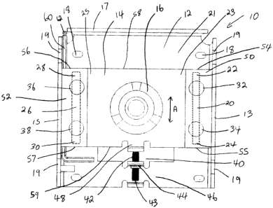
FIGURE 1. is a front view of a mounting bracket made in accordance with the
invention showing
the movable mounting plate in a position between its tirst and second
position.

FIGURE 2. is a front view of the mounting bracket shown in figure 1 showing
the movable
mounting plate in its first position.

FIGURE 3 is a front view of the mounting bracket shown in figure 1 showing the
movable
mounting plate in its second position.

FIGURE 4 is a perspective view of the invention.
FIGURE 5 is an exploded view of the invention.

In the drawings like characters of reference indicate corresponding parts in
the different
figures.

3


CA 02619787 2008-02-01

DETAILED DESCRIPTION OF THE IN VF?~TION

Referring firstly to figure I, a support bracket for use with a roller blind
is shown
generally as item 10 and consists of a base bracket 12 and a movable mounting
bracket 14
movable mounted to the base bracket. Bracket 14 has mounting fixture 16 which
is dimensioned

and configured to mount to and support the end of a roller blind (not shown).
Preferably, fixture
16 is configured to mount to both the clutch end of the roller blind (not
shown) or to the plug end
of the roller blind (not shown).

Base bracket 12 is provided with sides 13 and 15 and top 17 and back 21. Sides
13 and
and top 17 provide bracket 12 with structural strength. Preferably, bracket 12
is made of
10 stamped steel or some other suitably strong material. Apertures 18 and 19
are provided on

bracket 12 to permit the bracket to be mounted to a wall (not shown) by means
of mounting
screws (not shown). Mounting bracket 14 is movably mounted to bracket 12 by
means of rivets
32, 34, 36 and 38. Bracket 14 is essentially a flat metal plate having side
portions 23 and 25.
Elongated grooves 20 and 26 formed on side portions 23 and 25, respectively.
Groove 20 has

15 opposite ends 22 and 24 and groove 26 has opposite ends 28 and 30. Rivets
32 and 34 are fixed
to bracket 12 and to plastic gasket 50 and pass through groove 20. Likewise,
rivets 36 and 38 are
fixed to bracket 12 and to plastic gasket 52 and pass through groove 52.
Rivets 32, 34, 36 and 38
are dimensioned and configured such that bracket 14 can move up and down in
the direction
indicated by arrow A between a first position as shown in figure 2 and a
second position as

shown in figure 3.

Movable mounting plate 14 has top edge 58, bottom edge 59 and side edges 23
and 25
having grooves 20 and 26, respectively. Grooves 20 and 26 are elongated and
run essentially the
4


CA 02619787 2008-02-01

full width of plate 14 between edges 58 an~~ 511. Plate 14 has a butt portion
48 which is
configured to butt against adjustment bolt 42. Plate 12 has adjustment
mechanism 46 which
consists of adjustment bolt 42 mounted to threaded bracket 44. End 43 of
adjustment bolt 42 is
configured to receive end 62 of alien key 60 to permit a user to adjust the
position of plate 14

simply by turning bolt 42 with the allen key.

Plastic gasket 50 has upper and lower edges 54 and 55, respectively, and
gasket 52 has
upper and lower edges 56 and 57, respectively. Gaskets 50 and 52 form an
indicator indicating
the relative position of plate 14. The upper and lower edges of gaskets 50 and
52 provide a quick
visual means to determine the relative position of plate 14. Plates 14 are set
at a neutral position

as shown in figure 1 with edges 56 and 54 of gaskets 52 and 50, respectively,
level with top edge
58 and with lower edges 57 and 55 of gaskets 52 and 50, respectively, level
with bottom edge 59
of plate 14. When the plate is moved towards its first position, as shown in
figure 2, top edge 58
is raised above top edges 56 and 54. Since mounting fixture 16 is formed on
plate 14, the

distance separating top edge 58 from top edges 56 and 54 is the distance by
which fixture 16 has
I 5 been elevated. Likewise, when plate 14 is moved towards its second
position, as shown in figure
3, bottom edge 59 projects lower than bottom edges 57 and 55. The distance
separating bottom
edge 59 from bottom edges 57 and 55 is equal to the distance fixture 16 has
been lowered by.

Gaskets 52 and 50 are spaced away from plate 12 by a distance sufficient to
accommodate
movable mounting bracket (plate) 14. The space separating plate 12 and gaskets
52 and 50 is

also sufficient to accommodate allen key 60, so that the key can be stored
within bracket 10 until
it is needed for adjusting the relative position of fixture 16.

To use the mounting bracket of the present invention to mount a roller blind
(not shown),
5


CA 02619787 2008-02-01

the user first mounts a pair of brackets tt? r- -all or window frame as
required. The roller blind
may then be installed to determine if it will be level. If the roller blind is
not level, the user
simply uses allen key 60 to adjust the height of movable bracket 14 in one or
both of the
mounting brackets as required. Brackets 10 do not have to be repeatedly
repositioned on the wall

or window frame. Furthermore, the rollcr blind can he repeatedly tested in
order to make fine
adjustments to the level of the roller blind (not shown) by adjusting bolt 42.
In this way, the
level of the roller blind can be adjusted precisely in a quick and efficient
manner. The fascia can
then be mounted to the plate.

A specific embodiment of the present invention has been disclosed; however,
several

variations of the disclosed embodiment could be envisioned as within the scope
of this invention.
It is to be understood that the present invention is not limited to the
embodiments described
above, but encompasses any and all embodirnents within the scope of the
following claims.


6

Representative Drawing
A single figure which represents the drawing illustrating the invention.
Administrative Status

For a clearer understanding of the status of the application/patent presented on this page, the site Disclaimer , as well as the definitions for Patent , Administrative Status , Maintenance Fee  and Payment History  should be consulted.

Administrative Status

Title Date
Forecasted Issue Date 2010-12-21
(22) Filed 2008-02-01
Examination Requested 2008-02-01
(41) Open to Public Inspection 2009-08-01
(45) Issued 2010-12-21
Deemed Expired 2017-02-01

Abandonment History

There is no abandonment history.

Payment History

Fee Type Anniversary Year Due Date Amount Paid Paid Date
Request for Examination $400.00 2008-02-01
Application Fee $200.00 2008-02-01
Maintenance Fee - Application - New Act 2 2010-02-01 $50.00 2010-02-01
Final Fee $150.00 2010-10-05
Maintenance Fee - Patent - New Act 3 2011-02-01 $50.00 2011-01-11
Maintenance Fee - Patent - New Act 4 2012-02-01 $50.00 2012-01-13
Maintenance Fee - Patent - New Act 5 2013-02-01 $100.00 2013-01-22
Maintenance Fee - Patent - New Act 6 2014-02-03 $100.00 2014-01-23
Registration of a document - section 124 $100.00 2014-05-14
Maintenance Fee - Patent - New Act 7 2015-02-02 $100.00 2015-01-12
Owners on Record

Note: Records showing the ownership history in alphabetical order.

Current Owners on Record
V.B. KOTING MANAGEMENT INC.
Past Owners on Record
NG, PHILIP
WILLS, NORMAN
Past Owners that do not appear in the "Owners on Record" listing will appear in other documentation within the application.
Documents

To view selected files, please enter reCAPTCHA code :


To view images, click a link in the Document Description column. To download the documents, select one or more checkboxes in the first column and then click the "Download Selected in PDF format (Zip Archive)" or the "Download Selected as Single PDF" button.

List of published and non-published patent-specific documents on the CPD .

If you have any difficulty accessing content, you can call the Client Service Centre at 1-866-997-1936 or send them an e-mail at CIPO Client Service Centre.


Document
Description 
Date
(yyyy-mm-dd) 
Number of pages   Size of Image (KB) 
Claims 2010-05-20 4 107
Cover Page 2009-07-21 2 67
Abstract 2008-02-01 1 24
Description 2008-02-01 6 212
Claims 2008-02-01 4 107
Drawings 2008-02-01 5 226
Representative Drawing 2009-07-07 1 27
Cover Page 2010-12-03 2 67
Assignment 2008-02-01 2 150
Prosecution-Amendment 2009-11-24 1 26
Fees 2010-02-01 1 55
Prosecution-Amendment 2010-05-20 2 53
Correspondence 2010-10-05 2 117
Fees 2011-01-11 1 29
Fees 2012-01-13 1 28
Fees 2013-01-22 3 72
Fees 2014-01-23 1 30
Assignment 2014-05-14 6 240
Correspondence 2014-05-30 1 26
Fees 2015-01-12 1 30