Note: Descriptions are shown in the official language in which they were submitted.
CA 02619883 2013-06-28
23724-301
- 1 -
SEPARATOR HAVING A LIQUID OUTLET
INCLUDING A THROTTLING DEVICE
BACKGROUND
The present disclosure relates to a separator having
an at least inwardly singly or doubly conical separator drum
which is mounted rotatably at only one of its axial ends and
which has a vertical axis of rotation. The present disclosure
also relates to a method for three-phase separation by a
separator of this type.
Separators of this type are known. As a rule, liquid
discharges or outlets are provided with what are known as
stripping disks which utilize the effect whereby the rotational
energy of the inflowing liquid is converted to a dynamic
pressure in the outflow line. Stripping disks of this type
have proved appropriate. In particular, it is possible by
throttling to vary the prevailing dynamic pressure and
consequently to vary the separation zone in the drum or the
radius of the separation zone in the drum over a certain range
A. It is also known, in particular, to assign stripping disks
to both liquid outlets.
A known three-phase separator is illustrated in
FIG. 3. If a stripping disk is assigned to one or both of the
two liquid outlets from the drum and the further outlet is of
nozzle-like design, this results in a range delta LP, within
which the stripping disk, by throttling, allows a displacement
of the separation zone in the drum (see, for example,
WO 86/01436). Here, on the one hand, the range of
displaceability of the separation zone is still relatively low,
CA 02619883 2013-06-28
23724-301
- 2 -
and it is also not readily possible, via the stripping disks,
to displace the separation zone sufficiently quickly during
operation. Displacement also does not always lead to stable
process conditions, since the variation in the throttling of
the stripping disk sequences at the same time influences a
plurality of parameters of the process.
By contrast, the present disclosure relates to the
development of a separator in such a way that a displacement of
the separation zone within the drum over a greater radial range
is possible in a simple way during operation, while an improved
settability of the position of the separation zone is to be
possible. Furthermore, the present disclosure also relates to
a method for operating a separator of this type.
The present disclosure relates to a separator with an
at least inwardly singly or doubly conical separator drum which
is mounted rotatably at only one of its axial ends and which
has a vertical axis of rotation. The separator also includes:
only at its lower end or at its upper end, a rotary spindle for
driving the separator drum, which rotary spindle is mounted
oscillatingly about an articulation point; an inflow pipe for a
product to be processed at least two liquid outlets for a
lighter phase and a heavier phase, the liquid outlet for the
lighter phase being provided with a stripping disk; solid
discharge ports, preferably in the region of its largest inner
circumference; a separation plate stack arranged in the
separator drum; and the liquid outlet for the heavier phase
being followed outside the drum by a settable throttle device
which has an annular or throttle disk and is designed for
displacing the liquid radius,
CA 02619883 2012-10-18
23724-301
- 3 -
up to which the heavy phase extends in the drum, by a variation
in the outflow cross section for the heavy liquid phase, that
is to say by throttling.
In accordance with the present disclosure, an
improved controllability of the process is obtained. In
particular, that is an improved regulatability of the position
of the separation zone, also called the E-line.
It is also possible to compensate for changes both of
the product quantities (phase relation) and of the product
characteristic (in particular, density) and nevertheless to
keep the separation line virtually constant. Nozzle wear can
be determined and the service lives prolonged.
Throttle devices of the type of annular disks which
do not rotate during operation are known from the sector of
*15 solid-jacket worm centrifuges, i.e., from DE 102 09 925 Al or
DE 102 03 652 Al. Nevertheless, the drums of these centrifuges
are mounted in the region of both axial ends and not
oscillatingly, like centrifuges. This results in the
difference that the drums of the decanters or solid-jacket worm
centrifuges rotate about a defined axis, whereas separator
drums execute a certain precessional movement. It was
therefore assumed that the conditions at the annular outflow
gap are not sufficiently constant to achieve a defined setting
of the separation zone between the light and the heavy phase
and a displacement of the outflow radius of the heavy liquid
phase with the aid of an adjustable throttle disk. This
presumption, however, has not been confirmed. Contrary to
expectations, stable conditions are established, even at the
outflow gap of the separator, on the throttle disk. Instead,
ak 02619883 2012-10-18
23724-301
- 4 -
the throttle disk improves process efficiency and the fine
tuning and stability of the process.
The separator is suitable for the most diverse
possible three-phase separation tasks, in particular for crude
oil treatment, in which the crude oil is clarified of solids
and water is separated from the crude oil.
The present disclosure also provides a use of a
separator for crude oil treatment, in which the crude oil is
clarified of solids and water is separated from the crude oil.
The present disclosure moreover, provides a method
for the three-phase separation and clarification of a product
to be processed into at least two liquid phases and one solid
phase. The processing of the product takes place in a
separator, according to the present disclosure. A product to
be processed is provided and fed into the separator. The
separator is operated and, to set the separation zone, a
setting of the radius of the lighter liquid phase LP by the
stripping disk occurs and a setting of the heavier liquid phase
occurs HP and, consequently of the separation zone, occurs by
.20 the throttle device, i.e., the annular disk. The setting of
the separation zone takes place once during the separator
operation.
According to one aspect of the present invention,
there is provided a separator comprising: at least one of a
singly and doubly conical separator drum mounted rotatably at
only one of the drum's axial ends and the drum having a
vertical axis of rotation; a rotary spindle, located only at
one of the drum's lower and upper ends, is provided to drive
CA 02619883 2012-10-18
23724-301
- 5 -
the separator drum, the rotary spindle being mounted
oscillatingly; an inflow pipe for a product to be processed; at
least two liquid outlets, a first liquid outlet for a lighter
liquid phase and a second liquid outlet for a heavier liquid
phase, the first liquid outlet including a stripping disk; a
solids discharge port located in a region of the separator's
largest inner circumference; a separation plate in the
separator drum; and the second liquid outlet being followed
outside the drum by a settable throttle device having an
annular disk for displacing a liquid radius of the heavier
liquid phase, up to which radius the heavier phase extends in
the drum, by a throttling in an outflow cross section for the
heavier liquid phase.
According to one aspect of the present invention,
there is provided a method for a three-phase separation and
clarification of a product to be processed into at least two
liquid phases and one solid phase, the method steps comprising:
providing a separator that includes at least one of a singly
and doubly conical separator drum mounted rotatably at only one
of the drum's axial ends and the drum having a vertical axis of
rotation, a rotary spindle, located only at one of the drum's
lower and upper ends, is provided to drive the separator drum,
the rotary spindle being mounted oscillatingly, an inflow pipe
for a product to be processed, at least two liquid outlets, a
first liquid outlet for a lighter liquid phase and a second
liquid outlet for a heavier liquid phase, the first liquid
outlet including a stripping disk, a solids discharge port
located in a region of the separator's largest inner
circumference, a separation plate in the separator drum, and
the second liquid outlet being followed outside the drum by a
CA 02619883 2012-10-18
23724-301
- 6 -
settable throttle device having an annular disk for displacing
a liquid radius of the heavier liquid phase, up to which radius
the heavier phase extends in the drum, by a throttling in an
outflow cross section for the heavier liquid phase; providing a
product to be processed; feeding the product into the
separator; operating the separator; setting a separation zone
by setting a radius of the lighter liquid phase via the
stripping disk and setting a radius of the heavier liquid phase
via the throttle device; and the setting of the separation zone
taking place once during the separator operation.
Other aspects of the present disclosure will become
apparent from the following descriptions when considered in
conjunction with the accompanying drawings.
BRIEF DESCRIPTION OF THE DRAWINGS
FIG. 1 is a sectional view through one half of an
embodiment of a separator drum, according to the present
disclosure.
FIG. 2 is a sectional view through another embodiment
of a separator drum, according to the present disclosure.
FIG. 3 shows a separator drum, according to the prior
art.
FIG. 4 is a sectional view through a drive region of
the separator drums of FIGS. 1 and 2.
FIGS. 5a'; 5a", 5a"', 5b and 5c are tables
illustrating the effects of the separators, according to the
present disclosure.
CA 02619883 2012-10-18
23724-301
- 7 -
DETAILED DESCRIPTION
FIGS. 1 and 2 show separator drums 1 which have a
vertically oriented axis of rotation at radius ro, according to
the present disclosure. FIG. 3 shows a separator drum 1' of
the prior art.
The separator drums 1 are placed onto a rotary
spindle 2 which, for example, according to FIG. 4, is driven
(not illustrated here) directly or via a belt or in another
way, for example, a gear. The rotary spindle 2 may be
configured conically in its upper circumferential region.
The rotary spindle 2 is mounted oscillatingly by at
least one or more rolling bearings 3 on one side of the drum 1,
shown in FIG. 4 beneath the drum. Therefore, during operation,
because of residual unbalances, and contrary to what happens in
a decanter, a new axis occurs which executes a type of
precessional movement about the vertical axis ro, as suggested
in FIG. 4 where the inclination angle a is illustrated.
Designs are known in which a lower drum is virtually
"suspended" on an upper rotary spindle. Here, too, however,
the drum is rotatably mounted oscillatingly at only one of its
ends or adjacently to one of its axial ends.
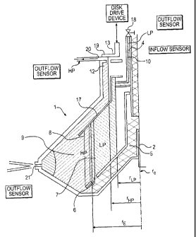
The separator drum 1 has an inflow pipe 4 for a
product P to be centrifuged. Pipe 4 is followed by a
distributor 5 which is provided with at least one or more
outflow ports 6 through which inflowing centrifuging product,
e.g., see the cross hatching, can be conducted into the
interior of the separator drum 1, as shown in FIG. 1. Also
shown is a riser channel 7 of a plate stack 8. It is
Mk 02619883 2012-10-18
23724-301
- 8 -
conceivable that a feed of product through the spindle 2, for
example, from below may be envisaged.
In the present disclosure, the embodiments shown are
such that the outflow ports 6 lie beneath the riser channel 7
in the plate stack 8, for example, at an outside diameter at
the location of reference symbol 8. Plate stack 8 includes
conically shaped separation plates 9. The plate stack 8 is
closed off upwardly by a partition plate 17 which has a larger
diameter than the plate stack 8.
Within the separation plate stack 8 and, for example,
within the riser channel 7, a separation zone between a lighter
liquid phase LP, i.e., the cross-hatching from bottom right to
top left and a heavier liquid phase HP, i.e., the cross-
hatching from bottom left to upper right is formed during
operation. This occurs in the case of a corresponding rotation
of the drum 1, at a specific radius, rE, the emulsion line or
separation line and also called the E-line.
The lighter liquid phase LP (light phase) is
conducted out of the drum at an inner radius rLp with the aid
of a stripping disk 10, also called a gripper. With the aid of
the dynamic pressure occurring as a result of the rotational
energy of the liquid, the stripping disk 10 acts in the same
way as a pump. The stripping disk 10 is followed, for example,
outside the separator, in its following discharge line by a
valve 18 for throttling.
By contrast, the heavy liquid phase HP flows around
the outer circumference of the partition plate 17 to a liquid
outlet 12 at the upper axial end of the drum 1 at radius rHp.
CA 02619883 2012-10-18
23724-301
- 9 -
The designs shown in FIGS. 1 and 2, to the extent
just described, correspond to one another. They may also be
provided with the same drive devices.
According to FIG. 3, the heavy phase HP flows out of
the drum 1 in the manner of an overflow at the liquid outlet
12'.
By contrast, the designs according to the present
disclosure, as shown in FIGS. 1 and 2, contrary to the design
of FIG. 3, are provided in the region of the liquid outlet 12
with a settable throttle device 13, with the aid of which the
cross section at the liquid outflow 12 is variable.
In order to implement throttle device 13 in a simple
way in structural terms, it is proposed, according to FIGS. 1
and 2, to arrange in the axial direction above the liquid
outlet 12, outside the drum 1, a type of annular or throttle
disk 19. Throttle disk 19 which is arranged and designed so as
to be spaced apart from the at least one liquid outflow port,
for example, liquid outlet 12, the position of the annular disk
19 in relation to the at least one outflow port being variable.
The disk 19 may have a planar surface or, for example, be
provided with grooves. The surface of the annular disk 19 may
be oriented perpendicularly to the drum axis.
The annular disk 19 may be arranged, for example,
axially displaceably or pivotably at one of its circumferential
edges. The annular disk 19 is assigned a drive which is
designed for varying the distance between the annular disk 19,
which may be stationary during operation, and the outflow port
12.
CA 02619883 2012-10-18
23724-301
- 10 -
The annular disk 19 may be designed to be stationary
during operation and does not co-rotate with the drum 1.
Between the annular disk 19 and the outflow ports 12,
a gap 20 is formed, through which the heavy liquid phase HP
flowing out of the drum 1 flows. A width of the liquid gap 20
is variable.
The radius of the E-line within the drum 1 can be
displaced over a certain range. This may be done both by the
throttling of the stripping disk 10 and by the adjustment of
the throttle device 19 or, of the gap width of the gap 20 by
the movement of the annular disk 19.
Here, the doubly conical drum 1 has, in the region of
its largest diameter, solid outflow nozzles 21 which serve for
the continuous discharge of solid particles S from the drum 1.
This configuration may be preferred. Embodiments without an
additional solid discharge may, however, likewise be envisaged.
The original presumption, that, when a moveable
annular disk 19 is used, sufficiently stable conditions at the
outflow gap 20 are not established on a drum mounted on only
one side or in an overhung manner, on account of the marked
precessional movement, since the gap 20 does not have a
constant gap width because of the precessional movement, has
not proved to be true. See the tables of FIGS. 5a', 5a",
5a"', 5b and 5c.
On the contrary, the displaceable annular disk 19
leads to a marked improvement in the settability of the
emulsion line, or E-line, and to a better manageability and
CA 02619883 2012-10-18
23724-301
- 11 -
controllability of the process. An enlarged setting range of
the separation zone is also obtained.
Thus, as mentioned above, the designs of FIGS. 1
and 2 are essentially identical to one another.
The outflow ports 12 may have a round shape in the
manner of bores or else, for example, widen in a wedge-like or
step-like manner from the inside outwardly, thus increasing the
regulatability in various instances. A small tube could also
be inserted into the outflow ports (not shown). An advantage
of this being that the liquid stream does not come to lie on
the drum 1.
As shown in FIG. 2, the liquid outflow 12 is preceded
by a type of hydrohermetic annular chamber 14.
This includes a disk 15 which precedes the liquid
outflow 12 within the drum 1 and which extends outward from the
outer circumference of the stripping disk 10. Disk 15 has a
maximum circumferential radius which is greater than a maximum
= radius up to which the outflow ports 12 extend. The stationary
nonrotating or closing disk 15 is preceded within the drum 1 by
a type of annular disk 16 as a first weir which extends
inwardly from the inner circumference of a drum cover of the
drum 1. The inner radius of disk 16 is smaller than the
maximum radius up to which the disk 15 and the outflow ports 12
extend, so that the hydrohermetic annular chamber 14 is formed,
as a second weir, on the inner circumference of the drum cover
of the drum 1 in the region between the annular disk 16 and the
outflow ports 12.
ak 02619883 2012-10-18
23724-301
- 12 -
This chamber 14 prevents the uncontrolled outflow of
gasses or vapor from the drum 1 through the outflow ports 12 or
labyrinths or other gaps or the like, which will result in a
brief instability in the region of the emulsion line, or E-line
or separation zone.
For pressure compensation, vertical bores 22, which
extend through the disk-shaped extension of the stripping disk
and are not operatively connected to the outflow duct in the
stripping disk, may be provided.
10 In practice, the embodiments of the present
disclosure have the following effect.
Improved control or settablity of the radius rE of
the emulsion line or E-line, also called, as noted above, the
separation zone or separation line. This significantly
increases the optimizability, stability and fine tuning of the
process in the three-phase separation system.
If it is assumed that the throttle device 13, by an
adjustable throttle disk 19, can adjust the discharge radius of
the heavy liquid phase HP by the amount of 10 ram and that the
stripping disk 10 can exert an additional pressure drop
of 100 000 Pa, this forms the possibility of setting the E-line
or of maintaining a stable E-line with different density rates
(K). See the tables of FIGS. 5a', 5a", 5a"', 5b and 5c.
The throttle device 13 alone can achieve an
adjustability of the discharge radius of the heavy liquid phase
HP of approximately 336 to 384 mm, that is to say, 48 mm, or a
compensation of a density ratio variance (K) of 0.884 to 0.915
(0.031). That occurs since, either by a reaction to
CA 02619883 2012-10-18
23724-301
- 13 -
displacements or else in the case of product changes, as a
result of a variation in the gap width of the gap 20 a
displacement of the separation zone is counteracted, in order
to keep this at as constant a radius as possible, so as to keep
the process stable.
By contrast, the stripping disk 10 alone can achieve
an adjustment of the radius of the separation line of 360 to
392 mm, i.e., 32 mm, or a compensation of the density change or
density ratio variance (K) of 0.878 to 0.900, i.e., 0.022.
In combination, the throttle device 13 and the
stripping disk 10 can achieve an adjustability of the
separation zone or of the radius of the E-line of 336 to 414
mm, i.e., corresponding to 78 mm, or a density ratio variance
(K) of 0.863 to 0.915, i.e., 0.052.
This shows, impressively, that, with the combination
of the stripping disk 10 the throttle device 13 and the solid
discharge nozzles 21, which nozzles 21 are followed by a
discharge system, for example, with guide plates or the like,
it is not only possible to adjust the E-line over a wide range,
but it is also possible to keep the E-line constant in a
particularly simple way. This is so, for example, when the
composition or property of the centrifuging product changes or,
due to nozzle wear, the machine properties change, for example,
the discharge cross section for the solid phase and
consequently the outflow quantity of the solid phase.
If, as shown in FIG. 2, a hydrohermetic chamber 14 is
provided, it is possible to prevent vapor or gas, for example,
hydrocarbons and/or water or oil vapor, from escaping from the
Mk 02619883 2012-10-18
23724-301
- 14 -
liquid, specifically independently of the process temperatures.
This affords the advantage that neither separation or
separation efficiency in the plate stacks 8 nor the position of
the E-line radius are influenced by water vapor.
. 5 It is also possible to provide a separate and
indepenlent water supply into the drum 1 (not shown) but
implementable, for example, by a concentric feed pipe within
the feed pipe 4 for the product and, further on, through the
distributor 5 into the drum 1, in order during a three-phase
separation, without an additional hydraulic load being exerted
on the plate stack 8, to ensure that a sufficient dynamic
pressure always prevails at the gap 20. If, however, there
were not a complete flow through the gap 20, an uncontrolled
displacement of the E-line would possibly occur.
The discharge volume flow through the gap 20 is
preferably observed and, if appropriate, also measured, in
order to prevent dry runs of this type and in order, as far as
possible, to minimize the volume of the water to be added.
In accordance with the present disclosure, it is also
possible and advantageous to measure the flow quantity of the
product to the centrifuge in exactly the same way as the flow
quantities at the outflows via the stripping disk 10 and
through the gap 20 at the throttle device 13. The discharge
rate of solids through the solid discharge nozzles 21 is
determinable from the differences between these variables.
The nozzle discharge capacity can initially be
determined theoretically on the basis of the machine design and
ak 02619883 2012-10-18
23724-301
- 15 -
of the rotational speed of the drum 1. This capacity is
designated below as the "nominal" capacity or discharge rate.
The difference between the nominal and the "measured"
discharge rates of the solid nozzles reproduces information on
' 5 the operating states of the nozzles 21.
If the "measured" discharge rate is higher than the
nominal rate, the nozzles 21 exhibit wear and a period of time
may be indicated, within which it is recommended to repair or
maintain the solid discharge nozzles 21. This is advantageous,
since it is possible to maximize the time up to the changing of
the nozzles 21.
If the measured "discharge rate" is lower than the
nominal rate, it can be concluded from this that one or more of
the solid discharge nozzles 21 are blocked.
The system, according to the present disclosure, may
be designed for carrying out an automatic correction of the
effect of nozzle wear, when it is established whether the solid
discharge nozzles 21 are blocked or not.
Finally, it is also possible to set up a type of
expert system for process optimization and regulation with the
aid of the separator drum 1, according to the present
disclosure.
The pressure drop across the throttle device 13 at
the gap 20 depends on the throughflow rate or throughflow
quantity and on the size of the gap 20. The pressure drop
across the stripping disk 10 depends on the throughflow
quantity and on the throttling pressure at the valve 18 of the
CA 02619883 2012-10-18
23724-301
- 16 -
stripping disk 10. The pressure drops influence the outflow
quantities of the heavy HP and the light LP phases. In
combination, and in each case considered separately, moreover,
the outflow line radii influence the position of the E-line.
Since it is clear how the heavy rHp and light rLp
outflow radii are influenced by the pressure drop at the gap 20
and at the stripping disk 10 and how this influences the
E-lines, an improved control and regulation system can be
provided for the separator.
Thus, from the fact that the radius of the E-line is
particularly small, the user can conclude that a higher
fraction of heavy phase HP is present in the light phase LP,
and vice versa.
If the emulsion is not separable, an emulsion layer
has built up within the centrifuge.
Since suitable variations in the settings at the gap
and/or at the stripping disk 10 are carried out, it is
possible either to prevent the occurrence of the emulsion layer
or to discharge this into the heavy HP or the light LP liquid
20 discharge, before the process becomes unstable or poorer
clarification takes place or before the process becomes
uncontrollable.
By an online expert system, a stable separation
process can be maintained, even though a fluctuation in the
product supply rate and product composition may occur or a
density fluctuation of the heavy HP and/or the lighter liquid
phase LP. Such effects arise, for example, in the case of
natural products, such as fish oil, or else in crude oil
CA 02619883 2012-10-18
23724-301
- 17 -
treatment, i.e., separation of water from the crude oil, or in
water treatment, i.e., separation of oil residues from the
water.
Since the online expert system is supplemented by an
online measurement of the throughflow quantity and/or of the
product flow quantity, it is possible to calculate the supply
density or, finally, to measure the density directly.
A correction of the flow quantity of the solids can
be carried out in that the solid content is measured, since the
solid density constitutes a relatively constant parameter.
By the discharge flow quantity of light phase LP and
the flow quantity being measured, the light phase density and,
finally, the density can be measured directly.
The inflow quantity and the outflow quantity of the
heavy HP and the light phase LP can be determined from the
densities.
From all these values, conclusions can be drawn which
make it possible to optimize the separation process by settings
at the gap 20 alone and/or by the suitable throttling of the
stripping disk 10.
This simple expert system may be supplemented by an
online measurement of the exact heavy phase HP composition and
of the light phase LP composition. Neither the heavy phase HP
nor the light phase LP typically possess a polarity which would
make the measurement of the volumetric concentration simple.
Although the present disclosure has been described
and illustrated in detail, it is to be clearly understood that
CA 02619883 2012-10-18
23724-301
- 18 -
this is done by way of illustration and example only and is not
to be taken by way of limitation. The scope of the present
disclosure is to be limited only by the terms of the appended
claims.