Note: Descriptions are shown in the official language in which they were submitted.
CA 02620146 2008-02-22
WO 2007/024288 PCT/US2006/015861
MULTILUMEN TRACHEAL CATHETER
WITH RINSE LUMEN
BACKGROUND
The present invention relates to a tracheal tube used for mechanical
ventilation of a
hospital patient, by insertion of the tube into the trachea of the patient. In
particular, the
present invention relates to a tracheal tube having means for irrigating
and/or evacuating
contaminated secretions accumulating above the tracheal tube cuff and thereby
reducing
the risk of such contaminated secretions entering the lungs of the patient.
Endotracheal intubation involves the insertion of a tubular device, known as
an
endotracheal tube, into the trachea of a patient. The endotracheal tube passes
through the
trachea and terminates at a position above the carina, anterior to a position
between the
second and fourth thoracic vertebrate. Gases may then be introduced through
the
endotracheal tube and into the lungs of the patient.
The primary purposes of endotracheal intubation, are to mechanically ventilate
the
patient's lungs, when a disease prevents the patient from normal, breathing
induced
ventilation, or to apply anesthetic gases during surgical intervention. In
order to create
enough air pressure to accomplish such mechanical ventilation and to prevent
escape of
gases past the tube, it is necessary to seal the passageway around the
endotracheal tube.
A seal may be produced by the use of an inflatable cuff formed integrally with
and
surrounding the endotracheal tube. When the endotracheal tube has been
introduced into
the patient's trachea, the inflatable cuff will normally be located about 3 to
5 centimeters
above the carina and within the tube-like trachea.
The inflatable cuff is then inflated so as to engage the wall of the trachea
and thereby seal
the trachea and prevent gases being introduced through the tracheal tube from
simply
backing up around the tube. While treatment of this sort has proved successful
for patients
having chronic or acute respiratory diseases, there is a constant risk of
several
complications.
In particular, many patients receiving endotracheal intubation develop
pneumonia,
resulting from an infection of the lungs, possibly induced by contaminated,
pooled
secretions entering the trachea and the lungs after bypassing the epiglottis
during
intubation. The epiglottis normally Operates as a valve which selectively
closes the entry
into the trachea and lungs, to prevent the introduction of secretions and
particulate matter.
However, when a tracheal tube is in place, the epiglottis is held in an open
position, and
secretions which would normally be directed away from the trachea and into the
digestive
1
CA 02620146 2008-02-22
WO 2007/024288 PCT/US2006/015861
system, instead follow the path of the endotracheal tube and pool above the
inflatable cuff
of the endotracheal tube.
The greatest risk of such infectious secretions reaching the lungs is upon the
cessation of
mechanical ventilation. In particular, when the need for endotracheal
intubation ends, the
inflatable cuff of the endotracheal tube is deflated so that the endotracheal
tube may be
withdrawn from the patient. The infectious secretions which have pooled above
the
inflatable cuff are then released and are free to flow into the lungs, where
bronchitis or
pneumonia may rapidly develop. There is also the risk of the infectious
secretions
reaching the lungs during the intubation, by aspiration of the secretions past
the tracheal
tube cuff.
To overcome these risks, it is known in the prior art to combine a single
lumen suction
tube with a tracheal tube. The suction tube is joined to the endotracheal tube
in a suitable
manner, the end of the suction tube terminating at a position above the
inflatable cuff. The
suction tube provides means for suction or evacuation of any pooled secretions
which
accumulate in the trachea above the inflatable cuff. However, such prior art
devices have
the disadvantage that use of a single lumen for the suction tube often causes
direct
suction to be exerted on the tracheal mucosa which may then result in damage
to the
mucosa.
U.S. Pat. No. 4,840,173 to Porter III, describes an endotracheal tube having a
single
lumen suction tube merged thereto. In particular, this patent describes a
device wherein
the suction tube is laminated to the outside of the ventilation tube, so that
the suction tube
terminates at a position just above the inflatable cuff. The suction tube
includes multiple
openings which may be used to evacuate secretions which pool above the
inflatable cuff.
In addition, the inflatable cuff includes a section immediately adjacent to
the end of the
suction tube that is less flexible than the rest of the inflatable cuff, to
insure that the flexible
material of the inflatable cuff is not sucked up against the suction tube
openings. The
endotracheal tube described in the Porter III patent has the disadvantages
noted above,
that the single lumen suction tube may exert suction on the tracheal mucosa
and thereby
cause damage to the mucosa. Further, the Porter III device is of a relatively
complex
design, requiring difficult processing, resulting in expensive production.
U.S. Pat. No. 5,143,062, issued to Peckham, discloses an endotracheal tube
comprising a
double lumen through which air may be circulated, creating an indirect gentle
suction
through a suction eye communicating with the distal ends of the lumens, and
located at a
position proximal to the inflation cuff. This design, however, does not
provide adequate
suction necessary for aspirating secretions and is easily occluded.
2
CA 02620146 2008-02-22
WO 2007/024288 PCT/US2006/015861
In fact, one problem that frequently arises in many of these catheters is that
the suction
port becomes occluded with secretions, rendering the function unusable. As
such, what is
needed is a multilumen catheter capable of suctioning secretions which have
pooled
above the inflatable cuff in a manner sufficient to accomplish the task but
not so strong so
as to cause damage to the mucosa. The suction function on such a device would
be
capable of being cleaned of accumulated secretions, preferably while in use.
The instant
invention addresses these problems by providing a multilumen tracheal tube and
suction
catheter system with a rinse function.
SUMMARY OF THE INVENTION
The present invention improves upon a tracheal tube by incorporating a rinse
lumen
therein. In one embodiment, the tracheal tube is formed from a flexible
cannula having a
length, a distal end, and a proximal end. The cannula consists of a plurality
of walls
extending substantially along the length of the cannula, dividing the cannula
into a plurality
of separate lumens including a respiratory lumen, a suction lumen, a rinse
lumen, and an
inflation lumen. An inflatable cuff surrounds the cannula proximal to the
distal end. The
inflatable cuff is adapted to seal the trachea of a patient. The inflation
lumen is in fluid
communication with the inflatable cuff. A port extends through a side wall of
the cannula
proximal to the inflatable cuff. The port is in fluid communication with the
suction lumen.
The rinse lumen may terminate within the suction lumen proximal to the port or
may
terminate within a chamber formed within the suction lumen, the chamber being
proximate
to the port.
In other embodiments, the tracheal tube may have a plurality of suction
lumens, a plurality
of rinse lumens, or both. Each suction lumen may terminate in a port and each
rinse
lumen may terminate within one of the suction lumens proximal to one of the
ports. There
may also be a plurality of rinse lumens for each suction lumen. A rinse liquid
is adapted to
be flushed through the rinse lumen and extracted via the suction lumen.
In still other embodiments, the tracheal tube may have an inflatable cuff
having a shape to
block a trachea beneath a glottis of the patient. A cannula may be disposed
through the
inflatable cuff. Such a cannula may contain a respiratory lumen, a suction
lumen, and a
rinse lumen. The suction lumen may have a port for suctioning a subglottic
space external
to the cannula while simultaneously enabling ventilation through the
respiratory lumen.
The rinse lumen may terminate within the suction lumen proximate to the port
or may
3
CA 02620146 2008-02-22
WO 2007/024288 PCT/US2006/015861
Terminate within a chamber formed within the suction lumen, the chamber being
proximate
to the port.
In any of the embodiments the tracheal tube may have a low profile extension
upon an
exterior surface of the cannula at the port to extend the effective reach of
the suction
lumen. The rinse lumen may terminate within the low profile extension.
In another embodiment a method of suctioning fluids from the subglottic space
within an
intubated patient is described. The method includes inserting a multilumen
catheter into a
patient's trachea, and inflating a cuff so as to sealingly engage the walls of
the trachea to
minimize the flow of fluids from the subglottic space into the patients lungs.
The patient
may be continuously ventilated through at least one lumen of the multilumen
catheter.
Suctioning of fluids from the subglottic space may be conducted through at
least one other
lumen. This lumen should have a port extending through a side wall of the
catheter
proximate to the cuff to access such fluids. This suction lumen may be rinsed
by
introducing a rinse liquid into the suction lumen proximate to the port
through at least
another lumen while suctioning fluids from the subglottic space. Rinsing may
be
accomplished under turbulent flow conditions, including as a spray.
Other objects, advantages and applications of the present invention will be
made clear by
the following detailed description of a preferred embodiment of the invention
and the
accompanying drawings wherein reference numerals refer to like or equivalent
structures.
BRIEF DESCRIPTION OF THE DRAWINGS
FIG. 1 is an elevational view of one embodiment of a multilumen catheter in
accordance
with the present invention;
FIG. 2 is a cross-sectional view of the FIG. 1 catheter at through line 2-2;
FIG. 3 is a cross-sectional view of the FIG. 1 catheter taken longitudinally
through the
catheter at the port region;
FIG. 4 is a cross-sectional view of an alternative embodiment of the FIG. 1
catheter,
depicting the chamber; and
FIG. 5 is a cross-sectional view of yet another embodiment of the FIG. 1
catheter,
depicting an optional low profile extension.
DETAILED DESCRIPTION
Reference will now be made to the drawings in which the various elements of
the present
invention will be given numeral designations and in which the invention will
be discussed
4
CA 02620146 2008-02-22
WO 2007/024288 PCT/US2006/015861
so as to enable one skilled in the art to make and use the invention. It is to
be understood
that the following description is only exemplary of the principles of the
present invention,
and should not be viewed as narrowing the pending claims. Those skilled in the
art will
appreciate that aspects of the various embodiments discussed may be
interchanged and
modified without departing from the scope and spirit of the invention.
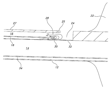
Referring to FIGs. 1 and 2, a tracheal tube 10 in accordance with one
embodiment of the
present invention is depicted. The tracheal tube 10 in the depicted embodiment
is a
multilumen cannula 12 having at least one respiratory lumen 14, at least one
suction
lumen 16, and at least one rinse lumen 18. In the embodiment, each of these
lumens is at
least partially internal to the cannula 12. The respiratory lumen 14 extends
through the
entire cannula 12 and is adapted to mechanically ventilate a patient (not
shown). As such,
a distal end 20 of the cannula 12 is situated within the upper respiratory
system of the
patient. A balloon, bladder, or inflatable cuff 22 is provided proximal to the
distal end 20.
The cuff 22 is shaped so that when inflated, it blocks the patient's trachea
beneath the
glottal area. This is known and understood by those skilled in the art to
eliminate or at
least to minimize the undesirable flow of fluids from the glottal and
subglottal regions of
the patient into the bronchus and lungs of the patient.
A port 24 extends from the suction lumen 16 through a wall 25 of the cannula
12 to an
exterior surface 27 of the cannula 12. The port 24 in the depicted embodiment
is
proximate to an upper surface of the cuff 22. As such, the suction lumen 16 is
adapted to
suction fluids that collect above the cuff 22 in the patient's subglottic area
without
negatively impacting ventilation of the patient through the respiratory lumen
14. The rinse
lumen 18, in this embodiment terminates within the cannula 12, specifically
within the
suction lumen 16 at an exit 30 as depicted in FIG. 3. Moreover, as depicted in
FIG. 3, the
rinse lumen 18 may terminate proximate to the port 24; or within a chamber 26
proximate
to the port 24 as depicted in FIG. 4. In either case, the rinse lumen 18
provides a path for
the introduction of a rinse liquid 28. This is depicted in FIG. 3 as a spray
pattern. The rinse
liquid 28 is introduced into the suction lumen 16 while the suction lumen is
suctioning or
otherwise evacuating the subglottic space. This is performed at the discretion
of the
caregiver in order to clean secretions and other liquids that may collect and
potentially
clog the suction lumen 16. In the embodiments depicted in each of FIGs. 1
through 4, the
rinse lumen 18 is situated so as to contain the rinse liquid 28 within the
suction lumen 16
and be suctioned along with the pooled liquids and other potentially clogging
secretions
contained within the suction lumen 16.
5
CA 02620146 2008-02-22
WO 2007/024288 PCT/US2006/015861
fle rinse liquid zti may comprise water, saline, as well as some other
biocompatible
liquid. A medicament, for example, an antiseptic or an antibiotic, or a
treatment such as a
surfactant may be added to the rinse liquid to obtain a desired effect on the
patient, or to
ease suctioning and/or cleaning of the suction lumen 16. Since the main
purpose of the
rinse liquid 28 is to rinse and/or clean the suction lumen 16, introducing the
liquid into the
suction lumen 16 in a turbulent manner will enable better cleaning of the
suction lumen. As
such the exit 30 of the rinse lumen 18 may be configured so as to foster
turbulent flow or a
spray pattern as depicted in FIG. 3. Moreover the shape of the chamber 26 if
existent may
contribute to such turbulence or provide a volume within which a spray may
desirably be
directed as depicted in FIG. 4.
Looking back once again to the cross sectional view of FIG. 2, one possible
configuration
of the tracheal tube 10 is depicted, more specifically a potential lumen
arrangement is
depicted within the cannula 12. As can be seen, the respiratory lumen 14 is
separated
from the suction lumen 16 by an internal wall 32 that extends substantially
along the entire
length of the cannula 12. Formed into the internal wall 32 is the rinse lumen
18 which as
described above terminates or exits at exit 30 within the suction lumen 16 or
within the
chamber 26, either being proximate to the port 24. This configuration is of
course only
meant to suggest one possible arrangement. Other arrangements are included in
the spirit
and scope of the invention. For example, the layout of the lumens within the
cannula 12
may be altered, moreover, the rinse lumen 18 may be formed in another wall,
such as wall
of the cannula or it may be a self contained lumen not embedded within any one
of the
walls of the cannula 12. FIGs. 2, 3 and 4 also depict an inflation lumen 34.
The inflation
lumen 34 is in fluid communication with the inflatable cuff 22 and as such
controls inflation
and deflation of the cuff 22 as would be understood by those of skill in the
art. FIG. 4
25 depicts the tracheal tube 10 in position, that is, with the balloon 22
seated against the
tracheal mucosa or tracheal wall 39 of the patient's trachea 37.
In other embodiments, a plurality of suction lumens 16 may be provided. Each
suction
lumen would be configured essentially as described above, in that each would
be rinsed
by a rinse liquid exiting a rinse lumen 18. A dedicated rinse lumen 18 may be
provided for
each suction lumen 16. The arrangement of lumens within the cannula 12 is not
limited in
scope to any particular configuration. Of course in each of the embodiments
described
more than one rinse lumen 18 may be provided for any one suction lumen 16.
Such an
arrangement may prove beneficial in more thorough rinsing of the suction lumen
or
lumens. Any of these embodiments are easily understood by one of skill in the
art as they
6
CA 02620146 2013-04-19
merely increase the number and arrangement of lumens provided. As such no
specific
drawings are needed for an understanding of these variations.
Yet in another embodiment, as shown in FIG. 5, a low profile extension 36 may
be
provided on the wall 25 of the cannula 12 such that it overlaps the port 24
and it extends
the effective reach of the suctioning capabilities radially outward a distance
from the wall
25 of the cannula 12 closer to the tracheal wall of the patient. In such
configurations the
exit 30 of the rinse lumen 18 may be placed as near as possible, including
within the low
profile extension 36 so as to more effectively rinse the suction lumen 16 and
extension 36.
Such an extension is disclosed in U.S. Patent No. 7,293,561.
In use, the caregiver would insert the multilumen catheter or tracheal tube 10
into the
patient's trachea 37 in a manner known and understood by those of skill in the
art. The
inflatable cuff 22 would be inflated through the inflation lumen 34 so as to
sealingly
engage the walls 39 of the patient's trachea 37. This would effectively
prevent or at least
minimize flow of undesirable fluids from the subglottic space into the
bronchus and lungs.
Ventilation of the patient through the respiratory lumen 14 may occur at this
time and
continue for as long as necessary. At the discretion of the caregiver, the
subglottic space
within the patient's trachea may be suctioned through the suction lumen 16 via
the port 24
through the wall 25 of the cannula 12. During suction, the suction lumen 16
may be rinsed
by introduction of the rinse liquid 28 through the rinse lumen 18. The rinse
liquid 28 may
be injected into the suction lumen 16 in a turbulent manner, including as a
spray at or near
the port 24 so as to better rinse the entire lumen 16. Rinsing the suction
lumen 16 at the
same time that suctioning is performed serves at least two function, the first
is that it
minimizes the inadvertent flow of the rinse liquid out of the cannula 12 and
into the
patient's subglottic space, and the second is that it increases the turbulent
flow of the rinse
liquid at the port and throughout the suction lumen as well. Alternatively, a
treatment may
be added to the rinse liquid such as a medicament, for example, an antiseptic
or an
antibiotic. In that case, it may be desirable to allow the rinse liquid to
exit the cannula 12
so as to gain the desired therapeutic effect prior to suctioning.
As used herein and in the claims, the term "comprising" is inclusive or open-
ended and
does not exclude additional unrecited elements, compositional components, or
method
steps.
7
CA 02620146 2013-04-19
,
The scope of the claims should not be limited by the preferred embodiments set
forth herein, but should be given the broadest interpretation consistent with
the
description as a whole.
8