Note: Descriptions are shown in the official language in which they were submitted.
CA 02620511 2008-02-05
WO 2007/017618 PCT/GB2005/003121
1
A Voltage Regulation Device
This invention relates to the control of the voltage of the electrical supply
to a property
for the purpose of energy saving and to improve the performance of, and
prolong the life
of, electrical appliances connected to the supply, and further concerns a
voltage
regulation device for such purpose.
In many parts of the world electrical distribution companies deliver power to
end users at
the upper end of a permitted range of voltage. For example, a typical average
supply
voltage in the UK and certain other parts of the world may be around 240 volts
where the
permitted statutory European voltage range is 216-252V. To reduce the supplied
voltage to, say, 230V would have no negative impact upon the consumer, and in
fact
there are many benefits to be gained by maintaining the supply at 230V. Such
benefits
include a reduction in the cost of the energy consumed, an increased life
expectancy of
electrical appliances, and a reduction in excessive CO2 emissions resultant
from
supplying electricity at an unduly high voltage level. It has been shown that
a 5%
reduction in voltage will yield an average 8% reduction in energy consumption.
Most currently manufactured electrical appliances for use in Europe are
designed to
operate at a nominal voltage of 230V. Running these appliances at a higher
voltage will
reduce their expected operating life. With the voltage typically supplied at a
level at or in
excess of 240V this not only wastes electrical power but severely shortens the
expected
lifetime of, for example, light bulbs and some expensive consumer items such
as
television sets.
Energy saving and reducing carbon emissions are high priorities for most
governments.
Increasing demand upon electrical networks means that governments are looking
for
new sources of power generation whilst having to meet the reduction in CO2
emissions
agreed under the Kyoto Protocol. Thus, widespread adoption of a voltage
regulation
device particularly, though not exclusively, for domestic and commercial
premises would
result in a distributed energy management system which would reduce the power
demand on the electrical networks and help to reduce emissions resulting from
power
stations.
It is therefore an object of the present invention to provide a voltage
regulation device
which can be readily installed in a property and which is sufficiently compact
and
inexpensive to manufacture to encourage consumers to obtain and use such a
device.
CA 02620511 2008-02-05
WO 2007/017618 PCT/GB2005/003121
2
Voltage regulation devices are known and consist of an autotransformer
connected to
the electrical supply and including a phase angle or pulse width modulation
(PWM)
switching means which can be used to switch the autotransformer in and out of
circuit as
required thus to determine and control the output voltage supplied to
appliances. The
PWM control is used to vary the length of time when the autotransformer is
switched in
and out of circuit thus to control its output voltage. The voltage regulation
device is used
to switch inductive loads. Usually lossy snubber circuits have to be used to
switch
inductive loads, but a soft switching approach can be used to improve the
efficiency of
the voltage regulation device. Such a device is described in a paper by Prasad
N. Enjeti
entitled "An approach to realize higher power PWM ac controller" published in
the IEEE
conference proceedings of APEC held in 1993, and in US patent 5747972. These
publications describe the use of an autotransformer in "buck" formation
connected to an
electrical supply and controlled by a PWM controller to determine a set
voltage which,
for Europe, may be 230V. The autotransformer is used to regulate domestic
voltage by
reducing the voltage to a set point if it is too high or by increasing it to
the set point if it is
too low. The device described in US574792 is implemented by connecting it into
the
incoming power supply to a property so that the device regulates the entire
power supply
to that property including predominantly resistive loads such as electric
cookers and
electric showers as well as highly inductive loads such as, boilers, fridges,
etc.
In a typical UK residence the consumer unit is often protected by a 100 amp
breaker
switch and so any voltage regulation device adapted for connection to all
circuits must
be rated for the maximum current of 100 amps. This requires an autotransformer
having
a rating of something like 24kVA which is physically very large, heavy and
expensive. It
may for example weigh in excess of 35kgs and in many instances its cost would
outweigh its value in controlling voltage levels in domestic premises.
Therefore, in order
for a voltage regulator to be effective and economically sound its size,
weight and cost
must be significantly reduced.
Testing has confirmed that some loads benefit greatly from voltage regulation,
for
instance lighting circuits, refrigerator/freezer and appliances containing
motors or
transformers, whereas resistive heating loads such as electric showers,
immersion
heaters and cookers do not benefit from voltage control. The loads that
benefit from
voltage control tend to constitute the majority of the base load of a property
and
contribute to the majority of the electrical energy consumed (kWh). Voltage
control of the
CA 02620511 2008-02-05
WO 2007/017618 PCT/GB2005/003121
3
circuits containing these loads will achieve the best savings whilst
minimising the size of
the autotransformer. Loads that do not benefit from voltage control make up
most of the
short duration, peak loads that result in property connection to the network
being rated
at much higher current than would be required of the base load. Specific
circuits
containing loads such as electric cookers, electric showers and immersion
heaters
would not therefore be controlled.
The reduction in the size of the autotransformer has been achieved according
to the
present invention by providing a voltage regulation device comprising-an
autotransformer
adapted for connection to an electrical supply, cyclic switching means
connected to the
autotransformer to determine its output voltage and means responsive to a
variation in
the operating temperature of the autotransformer and connected to the cyclic
switching
means to vary said output voltage and thus.control said operating temperature.
The temperature response means may be a thermistor adapted continuously to
measure
the temperature of the -autotransformer, or a thermal model calculation to
estimate the
autotransformer core temperature, and in the event of an increase of said
temperature to
cause switching logic to increase the output voltage of the autotransformer.
The device may include a bypass switch operable automatically to bypass the
autotransformer if its output voltage is substantially equal to that of the
electrical supply.
The device may be contained within a domestic electrical consumer unit wherein
at least
two output terminals are provided at least one of which is to supply
electrical power to
one or more circuits that will benefit from voltage regulation, and at least
one other is to
supply electric power to one or more circuits that will not benefit from
voltage regulation,
the device being connected between the main electrical supply and the or each
of the
circuits that will benefit from voltage regulation.
An embodiment of the invention will now be described, by way of example only,
with
reference to the accompanying drawings in which:
Fig. 1 is an illustration of how the voltage regulation device in accordance
with the
invention may be incorporated into a domestic consumer unit; and,
Fig. 2 is a block circuit diagram of the voltage regulation device
incorporated therein.
CA 02620511 2008-02-05
WO 2007/017618 PCT/GB2005/003121
4
For the purpose of this description it will be assumed that the voltage
regulation device is
adapted for connection to a varying electrical supply operating within a range
of 230V
plus or minus 10% which is the statutory range required under European
electrical power
legislation, and it will further be assumed that a constant output voltage of
230V is to be
maintained by the device.
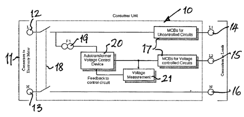
Referring now to Fig. 1 a domestic consumer unit is represented at 10 and is
supplied
with electricity from a meter 11 having output live and neutral terminals 12
and 13
respectively. Within the consumer unit 10 the live supply is divided to supply
two live
output terminals 14 and 15 and a neutral output terminal 16. MCBs or other
safety
devices 17 are included in the supplies to each of the terminals 14 and 15.
Terminals 14
and 16 are connected by a main isolating switch 18 directly to the terminals
12 and 1.3,
via the associated MCBs 17, in the case of terminal 14.
In accordarice with the invention the output terminal 15 is connected to the
live terminal
12 via a fuse 19 and, in this embodiment, a voltage control device 20
connected to a
voltage measurement unit 21 to provide feedback to control the device 20. The
voltage
measurement unit 21 could also be connected between the fuse 19 and the
voltage
control device 20, to provide feed forward control of device 20.
Referring now to Fig. 2 the voltage control device 20 comprises a switched
autotransformer 22, a microcontroller 23, a temperature measurement device 24,
the
voltage measurement device 21 and a bypass switch 26.
The microcontroller 23 includes switching logic 25 and a pulse width
modulation
(PWM)/phase angle control unit 27. The switching logic is designed to produce
a signal
representative of a voltage set point appropriate for the application of the
device which
signal is fed to the PWM unit 27 to control the cyclic switching of the
autotransformer 22.
As has been described, the voltage regulating device is adapted to supply a
constant
pre-determined voltage (set point) to the circuits that will benefit from
voltage regulation
connected in circuit, to terminal 15 of the consumer unit. Circuits that will
not benefit
from voltage regulation are connected directly to the supply at terminal 14.
CA 02620511 2008-02-05
WO 2007/017618 PCT/GB2005/003121
The current drawn by the regulated circuit will typically be in the region of
3 amps or less
but will vary according to the number of appliances being used at any one
time. It is
generally accepted that for approximately 30% of any twenty-four hour period
the
demand is typically as low as 0.5 amps drawn by such devices as televisions
and other
5 electronic components which are in a"standby" mode. For another 65% of the
time, the
load is typically between 1 and 4 amps but for short periods of an hour or so
this
demand may increase to something in the region of 20 amps for example when
washing
machines and tumble dryers are in use. It is also known that occasional
transient
demands possibly of up to 40 amps may be made for very short periods of
perhaps
fifteen minutes in any twenty-four hour period.
Thus, the autotransformer 22 may be rated for a base load of, say, 20 amps
rather than
the full or maximum rating of the supply circuit which could be, for example,
100 amps.,
ie, less than a quarter of the maximum and can be derived from a single phase
500VA
isolating transformer reconfigured to produce a 5KVA autotransformer capable
of
supplying 20 amps continuously. Such a-device is compact and weighs something
in the
region of 3.5 kg and is thus small and light enough to be packaged within a
standard
consumer unit. Such a small transformer is also relatively inexpensive in
manufacture.
As stated above, at times the demand placed upon the voltage regulating device
may
exceed 20 amps and in such circumstances the autotransformer will start to
heat up.
For this purpose there is provided a temperature sensing component such as a
thermistor which is connected in a feedback loop with the autotransformer via
switching
logic.25 of the microcontroller 23. Thus, the cyclic switching of the
autotransformer,
when its temperature rises will be adjusted to increase the output voltage
thus reducing
the stress on the autotransformer and allowing it to cool down. The voltage
set point will
be increased gradually so as to produce no noticeable change in the
performance of
electrical appliances in operation at the time when the voltage is increased.
Alternatively, a thermal model can be used to estimate the autotransformer's
core
temperature. The estimated temperature can be used in the same manner as
described
previously to adjust the cyclic switching of the autotransformer. This
provides a
mechanism for reducing the stress on the autotransformer allowing it to cool
down.
In times of heavy load the temperature of the autotransformer may increase to
such a
level that its voltage set point is increased by the switching logic to a
level where it
substantially equates to the input voltage. At this point the switching logic
will
CA 02620511 2008-02-05
WO 2007/017618 PCT/GB2005/003121
6
automatically operate the bypass switch 26 thus to take the autotransformer
out of circuit
until it has cooled down adequately as detected by the thermistor 24, or
thermal model.
It will be appreciated that by making the estimated load assumptions, and by
controlling
the autotransformer in this way on those rare occasions when an excessive load
is
applied, it is possible to provide a much smaller and less expensive
transformer than
would be required to withstand such high loads without temperature control.
This
enables the adoption of a compact, lightweight and inexpensive transformer
which can
be readily housed within a standard consumer unit of the kind used in domestic
premises. The control over voltage supplied by such a consumer unit to
circuits that will
benefit from voltage regulation results in considerable cost saving in energy
consumption and far outweighs the additional cost of a consumer unit equipped
with
such a device. In turn, the consumption of power at an overall reduced voltage
serves to
ensure an overall reduced power demand upon the supply network and reduced COZ
emissions from power stations.
It is not intended to limit the invention to the details described. For
example, a compact
voltage regulation device of the kind described may be located outside of the
consumer
unit but alongside it and thus perhaps available as a device to be connected
to an
existing consumer unit with minor adjustments to the circuitry therein thus to
divide the
supply circuitry into two parts, one for the circuits that will not benefit
from voltage
regulation , and the other for the circuits that will benefit from voltage
regulation where a
reduced and constant voltage will save energy and prolong the life of the
appliances.
Also, the device may be constructed and operated at different voltage levels
such as
those which are customary in other countries.
As well as providing power savings, the voltage control device will also
provide a level of
power factor correction for the circuits it regulates. The flux density in
iron circuits is
proportional to voltage, and the higher the flux density the higher the iron
losses in the
circuit. Therefore, by reducing the voltage there will be a reduction in the
flux density,
and a corresponding reduction in the iron losses. This will result in an
improved power
factor for the circuit. This improvement in power factor will benefit
distribution,
transmission, and generator companies.