Note: Descriptions are shown in the official language in which they were submitted.
CA 02620536 2008-02-07
Supply air terminal unit
The invention concerns a supply air terminal unit.
Separate machine rooms in connection with supply air arrangements are known in
the state of the art.
This application presents a supply air terminal unit solution of quite a new
type,
whish is especially suitable for use as a supply air terminal unit for
mounting on
the roofs of buildings and which looking from the direction of airflow
comprises a
heat-transferring pre-filter wall, an air fine filter and possibly also a
second heat-
ing step. According to the invention, the filter wall of the pre-filter is
made of
needle-fin tubes in the unit. The pre-filter is placed in the unit's interior
space E as
a peripheral structure, whereby air will arrive in space E from the sides.
As presented in this application, the needle-fin tube comprises a band wound
around the tube proper and comprising in two rows needle-like fins, which are
positioned at an angle in relation to one another. Said adjacent needle fins
thus
form an acute angle in relation to each other, in which angle impurity
particles
will depending on their size be caught in the filtration event. In the needle-
fin
tube proper, heat can be transferred through the fins from the air or the air
can be
heated in the opposite direction through the needle-fin tube.
According to the invention, the unit is formed by a box-like and preferably
rec-
tangular cross section or also in one embodiment of a circular cross section.
As
described above, as seen in the supply air flow LI, the first component is at
least
one filtering wall 12 formed of needle-fin tubes. The wall in question is a
periph-
eral structure positioned around a second filter 13. Inside the wall 12 formed
by a
needle-fin tube there is thus a fine filter 13, which is formed as a cassette-
like
modular unit, which when contaminated can be easily exchanged and/or cleaned.
CA 02620536 2008-02-07
2
The air supplied through the supply air terminal unit 10 can be either cooled
or
heated and filtered with the aid of the needle-fin tube wall 12. In the
direction of
the airflow L1 , the equipment may after the pre-filter 12 also comprise a
separate
heating coil (not shown) in order to produce a final temperature for the
airflow LI.
The filters, pre-filter and fine filter or after-filter as well as a possible
after-heater
are fitted into the unit in this manner. Above the concerned structures there
is an
opening top cover, whereby the structures are easily accessible for service in
order
to clean / exchange / inspect them, whereby the serviceability of the unit is
good.
It was realized in accordance with the invention to fit the after-filter or
fine filter
13 to cover an outlet port A2 located in the bottom of the supply air terminal
unit.
In accordance with the invention, in connection with the outlet port A2 there
is a
latticework, on top of which the filter modules are piled to form a uniform
fine
filter. In connection with service work it is easy to exchange each module by
opening the top cover of the supply air terminal unit. Service work according
to
the invention is easily done, because there is easy access to the filter
modules
from above. According to the invention, the filter modules are thus resting on
the
latticework, and each one of them is fastened by screws or other such clamps
to
lattice beams or other such. When the airflow is leaving the after-filter or
fine fil-
ter modules 13a1, 13a2, the airflow has a direction L1', which is essentially
per-
pendicular in relation to the direction of arrival of the air in the chamber E
inside
the unit.
The supply air terminal unit in question can be mounted either on a roof or
also
inside the building. For the supply air flow, the unit comprises an opening
above
and below and possibly a lattice therein. The opening is also formed as a
circular
flow gap.
The supply air terminal unit according to the invention is mainly
characterized by
the features presented in the claims.
CA 02620536 2014-05-27
2a
In one aspect, the invention provides a supply air terminal unit, which
comprises:
a body and therein side walls as well as a top wall and a bottom wall; and
an opening / closing cover, which is opened to allow access for service work
in the
supply air terminal unit into a service space;
wherein the supply air terminal unit comprises a central fine filter, before
which a wall
structure is fitted formed by needle-fin tubes, wherein the needle-fin tubes
are placed on
top of each other to form a filter wall and wherein the needle-fin tube has
needle-like
fins, whereby a heat carrier flows in the needle-fin tube and heat is
transferred from the
heat carrier into the air through the needle-fin structure or in the opposite
direction from
the air into the heat carrier; and
wherein the fine filter covers an air outlet port located in the bottom of the
supply air
terminal unit.
CA 02620536 2008-02-07
3
The invention will be described in the following by referring to some advanta-
geous embodiments of the invention, which are shown in the figures of the ap-
pended drawings, but there is no intention to restrict the invention to these
em-
bodiments alone.
Figure 1A is an axonometric view of the supply air terminal unit according to
the
invention. Figure 1B is a cross-sectional view along line I-I of Figure 1A.
Figure
1C is a cross-sectional view along line II-II of Figure IA. Figure 1D is an
illustra-
tive view of a module 13a1, 13a2..., which is placed in connection with a
lattice-
work.
Figure 2 shows how the supply air terminal unit is placed on a roof and on a
wall
in a building.
Figure 3A shows the needle-fm tube according to the invention. Figure 3B is a
cross-sectional view along line of Figure 3A. Figure 3C shows the fin band
of the needle-fin tube glued on to the tube as a cross-sectional view along
line IV¨
IV of Figure 3B. Figure 3D shows the structure in the direction of arrow K1 in
Figure 3B. Figure 3E shows a filter wall formed by needle-fin tubes in connec-
tion with inlet manifolds J1 and J2.
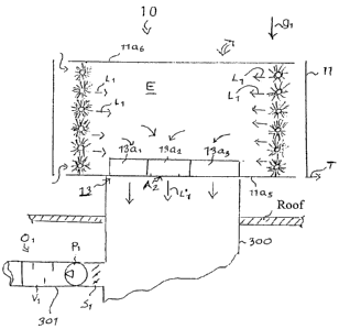
Figures 1A, 1B and 1C show the supply air terminal unit 10 according to the in-
vention. The supply air terminal unit 10 comprises a box structure 11, which
comprises side walls 11a1, 1a2, 1 la3 and 11a4 and a bottom wall 11a5 as well
as
an opening top cover 11 a6. An airflow gap D1 and D2 is left on each side of
the
square structure in its upper and lower parts, whereby air can be made to flow
as
shown by arrows L1 from outside into the space E inside the structure and from
space E in the direction of arrow L1' and out through an outlet port A2.
CA 02620536 2008-02-07
4
As shown in the Figures 1A, 1B and 1C, and seen in the direction of the supply
airflow LI, the supply air terminal unit 10 comprises a first filter 12, which
is a so-
called pre-filter, which preferably is a coarse-mesh filter and formed by
needle-fin
tubes in accordance with the invention. The needle-fin tubes are placed on top
of
one another and they form a wall structure functioning as a filter and as a
heat
exchanger. (Figures 3A, 3B and 3C show the structure of a needle-fin tube).
After
the pre-filter 12 in the flowing direction of airflow L1 a fine filter or
after-filter 13
is located.
As shown in the figures, the pre-filter 12 is fitted around the after-filter
13 as a
peripheral structure to surround it. By the above-mentioned location of the
filters
around duct 300 a large filtering cross-section is achieved and
correspondingly a
small pressure loss over the filters. The device 10 preferably comprises a
pressure
sensor 17a1 in front of the filters 12, 13 and a pressure sensor 17a2 after
the filters
12, 13 in relation to the direction of flow LI, whereby in the device solution
any
pressure difference will be detected between the sensors 17a 1, 17a2 and thus
the
purity of the filters 12, 13 is indicated as well as their possible degree of
clogging
and need for exchange.
If the filters 12, 13 are clogged and they must be washed / exchanged, this is
eas-
ily done in the structure according to the invention by opening the supply air
ter-
minal unit's top cover 11a6, whereby there will be access to the filters 12,
13 in
space E. Space E can be a service space. The pre-filter 12 can be washed by a
jet
of water under pressure, and the fine filter 13 can be exchanged or taken away
for
cleaning. The pre-filter's 12 filtration class is EU3 and the after-filter's
or fine
filter's 12 filtration class is EU7, EU8 or EU9 or even more efficient.
As shown in Figures 1A, 1B and 1C, after the pre-filter 12 formed by needle-
fin
tubes 100 there is a fine filter or after-filter 13. The fine filter or after-
filter 13 is
located in connection with the outlet port in chamber E of the supply air
terminal
unit 10, that is, in connection with outlet port A2 from space E in the bottom
of
CA 02620536 2008-02-07
chamber E. The fine filter 13 is arranged to cover the outlet port A2 tightly.
The
fine filter 13 is advantageously formed modularly of filter units 13a1, 13a2,
13a3..., which may be, for example, filter items of a size of 60 x 60 cm,
which are
piled to cover the air outlet port A2 on top of the latticework 200. A compact
filter
5 13 is also possible. The latticework 200 may comprise elongated metal
fins
f2. = ., which extend through port A2 and on top of which the filter modules
13a1,
13a2, 13a3... are piled to rest by gravity (the direction of the earth gravity
field is
indicated by an arrow gi). The flow away from filter 13 along duct 300 is in
the
direction of arrow L1', that is, in the direction of the earth's gravity field
gi and
essentially at right angles in relation to the flow L1 taking place from pre-
filter 12
into space E. To port A2 a barrel or outlet duct 300 is connected, which
branches
off into branch ducts 301, 302, 303, each one of which may comprise an air
condi-
tioner 01, 02... comprising a damper S1, after this a fan P1 and a noise trap
VI.
The outlet duct 300 is also a supply air duct into the building. However, no
sepa-
rate filter is needed in the concerned air conditioner 0, because the filter
for the
entire structure is formed by the supply air terminal unit 10 according to the
in-
vention with its pre-filter 12 and fine filter 13. Each air conditioner 01, 02
located
in the branch duct 301 of the barrel or outlet duct 300 comprises a fan P1,
P2.
and these can be operated independently of each other. The functioning ability
of
the system is guaranteed by the linear conductance of the pre-filter 12 used,
which
is formed by needle-fin tubes 100, which makes it possible for the heat
exchange
in regard to the pre-filter 12 to work both at low fan speeds and airflow
rates and
also at high fan speeds and airflow rates. The after-filter or fine filter 13
works
perfectly at all times, because after the pre-filtration the air is clean and
dry. This
is guaranteed by the needle-fin tube structure used as the pre-filter
structure.
The pre-filter 12 is formed by filter modules 13a1, 13a2, 13a3..., which are
piled to
cover the outlet port A2. This makes easy serviceability of the structure
possible,
because the supply air terminal unit 10 comprises an opening cover 11a6, which
when opened allows easy access into the service space D and to the filter 13
and
its modules 13a1, 13a2, 13a3... Figure 1D illustrates the modular filter
structure in
CA 02620536 2008-02-07
6
connection with the outlet port A2. The filter modules 13 are assembled on top
of
a lattice network f1, f2... covering the outlet port A2 and attached tightly
to the
lattices, for example, by screws. No bypassing leakage can occur. When the
filter
13 is exchanged, the attachment is opened and the filter modules 13a1, 13a2,
13a3
are removed from the structure by opening the top cover 11a6 in the manner
shown by arrow Mi. Top cover 11a6 can be turned carried by hinges to an opened
and closed position or it can be put aside when opening it. The modules 13a1,
13a2... rest under their own weight (the direction of the gravity field is
indicated
by gi) on top of lattices f1, f2... and they are attached to the lattices f1,
f2... in a
removable manner.
Figure 1D illustrates a module, the size of which can be 60 x 60 cm. Always de-
pending on the air volume of the supply air terminal unit, it is possible to
choose
the size of the supply air terminal unit's 10 opening A2 and thus the size of
the
lattice network f1, f2... and the modular after-filter 13 covering the same.
In the supply air terminal unit 10 according to the invention, the direction
of flow
Li of the airflow from pre-filter 12 into chamber D is essentially at right
angles in
relation to the direction of discharge L1' of the airflow from port A2 into
the exit
duct and into the supply air duct 300 of the building. Under these
circumstances,
airflow L1 changes its travelling direction by about 90 when leaving chamber
D
for the exit duct 300. Filter modules 13a1, 13a2... may be such structures,
that
they have several filter layers. The filter may be, for example, a conical
structure,
thus comprising an air space inside the cone.
A supply air terminal unit 10 which is to be placed on a roof may thus serve
sev-
eral supply air terminal devices 01, 02- = =
The supply air terminal unit 10 may be provided with pre-heating (heat
recovery),
cooling, pre-filtering (needle-fin battery) 12 and main filtration of the
supply air
and possibly also with an after-heating function (by needle battery 14) of the
sup-
CA 02620536 2008-02-07
7
ply air. The plane of port A2 is indicated by Ti. The filter 13 forms a plate-
like
structure located in a horizontal direction. The filter structure may be
formed by a
serrated profile in cross-section. The after-heating unit may be located in
space E
after the pre-filter 12 and it too may be formed by a wall formed by needle-
fin
tubes 100. It may also be located peripherally around the fine-filtration unit
13.
The supply air terminal unit 10 can be dimensioned for a smaller airflow than
the
totalled design airflow of the fans P1, P2... of the supply air terminal
devices serv-
ing the supply air terminal unit. This is due to the fact that the serving
supply air
fans Pi, P2... of the supply air terminal unit 10 will not probably ever be
working
all at the same time at full airflow. Calculated by a simultaneity coefficient
of 0,7,
the supply air terminal unit 10 can be dimensioned for an airflow which is
smaller
by 30 % in comparison with state-of-the-art heat recovery, cooling and
filtration
solutions for specific devices.
Figure 2 shows how the supply air terminal unit 10 is located in position A1 ,
that
is, on the roof of a building H, and the figure also shows another position
A2, in
which the supply air terminal unit is fitted on a wall of the building H.
Figure 3A shows a needle-fin tube 100 according to the invention. Figure 3B is
a
cross-sectional view along line 111-Ill of Figure 3A, and Figure 3C is a cross-
sectional view of a fin band along line IV¨IV of Figure 3B. Figure 3D shows
the
structure in the direction of arrow 1(1 of Figure 3B. As shown in Figures 3A,
3B,
3C and 3D, the needle-fin tube solution 100 comprises a central tube 120, to
which the fin band 121 is joined by winding it and attaching it around the
tube
120.
As shown in Figure 3B, the needle-fin band 121 has two adjacent needle rows n1
and n2, whose opposite needle fins 111 al, 111a2 are at an acute angle ai in
relation
to each other. Said angle ai is an acute angle, whereby impurity particles
will be
caught at various height positions in between adjacent fins 111ai, 111a2. The
nee-
CA 02620536 2008-02-07
8
die-fin tube 100 functions both as a filter and as a heat exchanger. Heat can
be
transferred through it from a heat carrier made to flow inside tube 120
through the
needle fins 111a1, 111a2... into the air or heat can be transferred in the
opposite
direction from the air from the flow Li through the needle fins 111a1,
111a2... into
the heat carrier made to flow centrally in tube 120, whereby the airflow L1
will be
cooled. Both purposes of use are possible. The fin band 121 comprises a base
part
a and folded covering parts b1 and b2, to which the needle fins 111a1,
111a2... are
joined. Thus, the needle-fin tube 100 can be used in the manner shown in
Figure
3E. The needle-fin tubes 100 are formed as a filter wall 12, whereby a heat
carrier
is conducted from the distributing manifold J1 into each needle-fin tube 120
on the
wall 12, and the heat carrier is removed from distributing manifold J2. Wall
12
forms the pre-filter's so-called coarse-mesh filter and a heat exchanger,
after
which the equipment comprises a fine filter 13, with which impurity particles
of a
smaller particle size can be removed from the air after the pre-filtration.