Note: Descriptions are shown in the official language in which they were submitted.
CA 02620813 2008-02-28
WO 2007/025367 PCT/CA2006/001398
SPARK GENERATION METHOD AND IGNITION SYSTEM USING SAME
FIELD OF THE INVENTION
[001] The invention relates generally to internal combustion engines, and more
particularly to spark generation for an internal combustion engine.
BACKGROUND ART
[002] Internal combustion engines are well known. In operational cycle of the
engine,
fuel and air are drawn into a chamber by movement of a piston away from an
inlet of
the chamber, the fuel is then compressed by movement of the piston in an
opposite
direction - toward the inlet, a spark ignites the fuel forcing the piston away
from the
inlet and then the chamber is partially evacuated by the final piston movement
toward
an exhaust thereof near the inlet end. Though according to a simplified ideal
theory a
single spark will consume all of the fuel within the chamber in a near
instantaneous
fashion, this is not the case in reality.
[003] Two prior art ignition systems that are very widely used are inductive
discharge
systems and capacitive discharge systems. The difference between the two
systems
i-elates mostly to an energy storage component used within each circuit where
the
inductive discharge system relies on an inductor and the capacitive discharge
system
relies on a capacitor. When using an inductive discharge based system energy
tends to
iall off at high revolutions per minute (related to strokes/minute) because an
insufficient dwell time, to charge the coil, is provided. Further, a resulting
low
secondary voltage rise makes sensitivity to spark gap fouling significant.
Typically,
energy delivered to the spark plug gap is in range of 20-50 mJ at 1-2 ms of
spark and
has decaying power across its duration.
[004] Capacitive discharge systems are known to release more spark energy over
a
relatively short period of time. Capacitive discharge systems produce up to
100 mJ of
1
CA 02620813 2008-02-28
WO 2007/025367 PCT/CA2006/001398
spark energy, but are characterized by limited spark duration of 150-500 ,us.
This very
short spark duration results in significant difficulty igniting fuel during
cold start
conditions, with lean mixtures, and during transient behaviour of carburetion.
Unfortunately, each of these systems provides only a single short duration
spark, and as
such, may fail to ignite all or a portion of the fuel within the chamber.
[005] Multi-spark ignition systems represent an alternative to traditional
inductive
discharge and capacitive discharge systems. In a multi-spark ignition system,
sparking
occurs repetitively over a period of time. This has been shown to better
influence
combustion initiation - more reliably ignite the fuel within the chamber. When
used on
cold engines, multi-spark ignition systems typically more reliably start the
engine. In
multi-spark ignition systems, an energy discharge and charge cycle is created
to charge
and discharge a spark generation circuit to produce sparks at intervals and
having
similar profiles. Another approach to multi-spark is to discharge the spark
generation
,;,ircuit in a fashion resulting in an oscillation that oscillates below and
above a sparking
threshold resulting in periodic sparking during discharge.
[006] Many multi-spark ignition systems rely on inductive discharge and as
such
provide lower energy discharge for a longer duration as disclosed, for
example, in US
Patent Number 6,397,827, wherein a high voltage is intermittently applied from
an
ignition coil for more than one time in a short time to generate sparks.
[007] Multi-spark systems including those disclosed in US Patent Number.
6,694,959
and U.S. Patent Number 6,085,733 and high-frequency ignition systems as
disclosed in
IJS Patent Number 6,729,317 provide for increased overall sparking time during
a
stroke. The multi-spark ignition systems are able to maintain spark discharge
above a
desired energy level for a longer proportion of the stroke, in an interrupted
and unipolar
fashion. The high-frequency ignition systems are complex and produce a
sinusoidal
output voltage that reduces the formation of efficient plasma in the spark
gap.
[008] It would be advantageous to provide a spark discharge ignition system
that
overcomes the drawbacks of the prior art.
2
CA 02620813 2008-02-28
WO 2007/025367 PCT/CA2006/001398
SUMMARY OF THE INVENTION
[009] Accordingly, it is an object of the present invention to provide an
ignition
system for internal combustion engines, which is simple and flexible.
[0010] According to the invention there is provided an ignition system for
providing
energy across a spark gap comprising: a first series closed circuit including
a DC power
supply, a primary winding of an energy storage coil and a first switching
device; the
first circuit for supporting a charge of the energy storage coil when the
first switching
device is conducting, and a discharge of energy stored within the energy
storage coil
when the first switching device is nonconducting; a second series closed
circuit
including a secondary winding of the energy storage coil, a first diode and an
energy
storage capacitor, the diode for preventing a flow of current from the energy
storage
capacitor to the secondary winding of the energy storage coil; a third series
closed
circuit including the secondary winding of the energy storage coil, the first
diode, a
primary winding of an ignition coil and a second switching device; the second
and the
third series closed circuits for supporting the discharge of energy stored
within the
~energy storage coil via the first diode to the energy storage capacitor when
the second
switching device is nonconducting, and to the ignition coil when the second
switching
device is conducting; a fourth series closed circuit including the energy
storage
capacitor, the primary winding of the ignition coil and the second switching
device; the
fourth circuit for supporting the discharge of energy stored within the energy
storage
capacitor to the ignition coil when the second switching device is conducting;
a fifth
series closed circuit including the DC power supply, a second diode, the
primary
winding of the ignition coil and the second switching device, the diode for
providing a
flow of current from the DC power supply to the primary winding of the
ignition coil
when the energy storage coil and the energy storage capacitor are discharged;
the fifth
circuit for supporting a charge of the ignition coil when the second switching
device is
conducting, and a discharge of energy stored within the ignition coil when the
second
switching device is nonconducting; and, a control circuit for generating a
first control
signal and a second control signal, the first control signal for operating the
first
switching device, and the second control signal for operating the second
switching
3
CA 02620813 2008-02-28
WO 2007/025367 PCT/CA2006/001398
device, wherein the components within the ignition system are chosen to
support
generation of a continuous spark across the spark gap.
[0011]Additionally, the invention supports an ignition system for providing
energy
across a spark gap comprising: a first series closed circuit including a DC
power
supply, a primary winding of an energy storage coil and a first switching
device; the
first circuit for supporting a charge of the energy storage coil when the
first switching
device is conducting, and a discharge of energy stored within the energy
storage coil
when the first switching device is nonconducting; a second series closed
circuit
including a secondary winding of the energy storage coil, a first diode and an
energy
storage capacitor, the diode for preventing a flow of current from the energy
storage
capacitor to the secondary winding of the energy storage coil; a third series
closed
circuit including the DC power supply, a primary winding of an ignition coil,
the
secondary winding of the energy storage coil, the first diode and a second
switching
device; the second and the third series closed circuits for supporting the
discharge of
energy stored within the energy storage coil via the first diode to the energy
storage
capacitor when the second switching device is nonconducting, and to of the
ignition
'coil when the second switching device is conducting; a fourth series closed
circuit
including the DC power supply, the primary winding of the ignition coil, the
energy
storage capacitor and the second switching device; the fourth circuit for
supporting the
discharge of energy stored within the energy storage capacitor to the ignition
coil when
the second switching device is conducting; a fifth series closed circuit
including the DC
power supply, the primary winding of the ignition coil, a second diode and the
second
switching device, the diode for providing a flow of current from the primary
winding of
the ignition coil to the second switching device when the energy storage coil
and the
energy storage capacitor are discharged; the fifth circuit for supporting a
charge of the
ignition coil when the second switching device is conducting, and a discharge
of energy
stored within the ignition coil when the second switching device is
nonconducting; a
control circuit for generating a first control signal and a second control
signal, the first
control signal for operating the first switching device, and, the second
control signal for
operating the second switching device, wherein the components within the
ignition
system are chosen to support generation of a continuous spark across the spark
gap.
4
CA 02620813 2008-02-28
WO 2007/025367 PCT/CA2006/001398
[0012] According to another aspect of the invention there is provided a method
of
ignition spark generation comprising: providing an energy storage coil;
providing an
energy storage capacitor; providing an ignition coil; storing energy within
the energy
storage coil; storing energy within the energy storage capacitor; storing
energy within
the ignition coil; switching the energy stored within each of the energy
storage coil and
the energy storage capacitor to the ignition coil for generating a spark
across a spark
gap; switching the energy stored within the energy storage coil to the
ignition coil for
generating the spark across the spark gap; switching the energy stored within
the
energy storage capacitor to the ignition coil for generating the spark across
the spark
gap; and switching the energy stored within the ignition coil for generating
the spark
across the spark gap.
[0013] According to another aspect of the invention there is provided a method
of
I~leaning a combustion chamber of an engine comprising: providing a first
spark profile
within the combustion chamber and during combustion, the first spark profile
for
Cleaning the combustion chamber and, when the combustion chamber is
sufficiently
clean, providing a second other spark profile within the combustion chamber
for
effecting operation of the combustion within known limits.
[0014] According to another aspect of the invention there is provided a method
of
cleaning a combustion chamber of an engine comprising: providing an ignition
system
having a first spark profile; determining a second other spark profile for
provision
within the combustion chamber and during combustion, the second other spark
profile
for cleaning the combustion chamber and, providing the second other spark
profile
within the combustion chamber.
[0015] According to another aspect of the invention there is provided a method
of
cleaning a combustion chamber of an engine comprising: providing fuel to the
engine;
in dependence upon the fuel type and mixture providing a first spark profile,
determined for the type and mixture of the fuel within the combustion chamber;
providing a second other fuel to the engine; and in dependence upon type of
the second
CA 02620813 2008-02-28
WO 2007/025367 PCT/CA2006/001398
other fuel providing a second other spark profile, determined for the type and
mixture
of the other fuel within the combustion chamber.
BRIEF DESCRIPTION OF THE DRAWINGS
[0016] Embodiments of the invention will now be described with reference to
the
attached drawings in which similar reference numerals designate similar items.
[0017] Fig. 1 is a schematic block diagram of a circuit according to an
embodiment of
the invention having two energy storage devices, an ignition coil, and two
switches for
independently being controlled;
[0018] Fig. 2 is a timing diagram showing signals generated during operation
of the
circuit of Fig. 1 for bipolar electrical discharge;
[0019] Fig. 3-4 are simplified schematic diagrams of the circuit of Fig. 1
with
,3dditional switch to change winding ratio of the storage coil, and storage
coil in the
form of autotransformer;
[0020] Fig. 5 is a simplified schematic diagram of the circuit of Fig. 1
coupled in a
imulti-channel fashion to a plurality of ignition coils and spark gaps;
[0021] Fig. 6-7 are schematic diagrams of a single channel embodiment suitable
to
being retrofit onto existing ignition control circuitry; and
[0022] Figs. 8-10 are simplified flow diagrams of embodiments of the
invention.
DETAILED DESCRIPTION OF THE PREFERRED EMBODIMENTS
[0023] In the description hereinbelow, the term ON is used with relation to a
switch
vvhen the switch is conducting current and OFF is used when the switch is
other than
conducting.
6
CA 02620813 2008-02-28
WO 2007/025367 PCT/CA2006/001398
100241 The terms continuous discharge and continuous spark discharge are used
herein
to refer to a continuous spark across the spark gap during the duration of
combustion,
for example the combustion stroke of an engine. A continuous spark discharge
will
span a plurality and often many energy storage and release cycles for a charge
storage
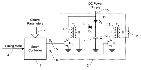
device within an ignition circuit.
[0025] Referring to Fig. 1, shown is a circuit diagram of an ignition system
in
accordance with an embodiment of the present invention. The ignition system
includes
spark controller 1 which provides a first control signal along conductor 5 and
a second
control signal along conductor 6. Along conductor 5, the first control signal
is provided
for controlling storage coil switch 8 and along conductor 6 the second control
signal is
provided for controlling ignition coil switch 12. A timing mark 3 is provided
to the
spark controller 1 for use in timing of spark control and control parameters 4
are
provided for use in controlling spark parameters in the form of spark duration
and spark
profile.
[0026] Also within the circuit diagram shown is a spark generation circuit 2
composed
of three functional groups. A first functional group comprises a series closed
circuit
comprising a DC power supply 15, a primary winding of storage coil 7 and
switch 8 in
the form of a transistor. A second functional group comprises a series closed
circuit
comprising a secondary winding of storage coil 7, blocking diode 9 and storage
capacitor 10. A third functional group comprises a series closed circuit
comprising the
DC power supply, blocking diode 11, a primary winding of ignition coil 13 and
switch
12 in the form of a transistor.
[0027] An operation of the storage coil 7 is controlled by the first control
signal S 1
along conductor 5. Energy is accumulated in the storage coil 7 when the switch
8 is ON
and is released through the blocking diode 9 when the switch 8 is OFF. The ON
time of
the switch 8 defines the amount of energy stored in the storage coil 7. The
OFF time of
the switch 8 defines the amount of energy of the storage coil 7 released
through the
blocking diode 9.
7
CA 02620813 2008-02-28
WO 2007/025367 PCT/CA2006/001398
[0028] The storage capacitor 10 fully or partially accumulates energy
transferred from
the storage coil 7 when the switch 8 is OFF.
[0029] An operation of the ignition coil 13 is controlled by the second
control signal S2
along conductor 6. When the switch 12 is ON, energy transferred from the
storage
capacitor 10, from the storage coil 7, or from DC power supply 15 is fully or
partially
accumulated in the ignition coil 13 and is fully or partially released through
a secondary
winding of the ignition coil 13 depending on a breakdown condition of spark
plug gap
14. When the switch 12 is OFF, the energy accumulated in the ignition coil 13
is
released through the secondary winding of the ignition coil 13 to the spark
plug gap 14.
[0030] There are several control methodologies for the energy transfer that
are
achievable in dependence upon different first and second control signals. For
example,
a simple ignition system allows for simple inductive discharge operation.
Here, the
second control signal operates with the capacitor 10 discharged, and the diode
11
conducting. When the switch 12 is set to the ON position, the ignition coil 13
begins
charging from the power supply 15 through the diode 11. When the switch 12 is
switched to an OFF position, electrical discharge occurs in the spark plug gap
14 with a
first polarity, for example a positive polarity. This results in a spark
profile similar to
that commonly achieved with known inductive discharge ignition systems having
a
~dwell time while the switch 12 is ON.
[0031] Different behaviour is observed when the capacitor 10 is charged to a
significantly higher voltage than the voltage of the DC power supply 15. When
the
,switch 12 is switched to the ON position, the rising current in the primary
winding of
the ignition coil 13 generates high voltage in the secondary winding
proportional to the
charge voltage of the capacitor 10 and causes breakdown of the spark plug gap
14 with,
:for example, negative polarity until the voltage of the capacitor 10 drops to
the voltage
of the DC power supply 15. This in isolation is known as a capacitive
discharge
ignition. When the voltage of the capacitor 10 is less than the voltage of the
power
supply 15, the diode 11 conducts and additional rising current from the power
supply
15 flows through the primary winding of the ignition coil 13. When the switch
12 is
8
CA 02620813 2008-02-28
WO 2007/025367 PCT/CA2006/001398
switched to the OFF position, the electrical discharge in the spark plug gap
14 changes
a polarity of the discharge current.
[0032] The use of the storage coil in the form of a transformer allows for
electrical
isolation and slower energy release to the ignition coil but supports a same
rate of
energy accumulation, or current rise, in its primary coil. This is highly
advantageous in
some applications. Of course the slower release results in a longer discharge
time
having a lower discharge peak energy.
[0033] Referring to Fig. 2, shown is a simplified timing diagram of signals
within the
circuit of Fig. I during bipolar spark discharge. At ti, when the ignition
coil switch 12
is ON, relating to the second control signal S2, the voltage of the storage
capacitor (10
in Fig. 1) VCAP has an initial value 16, and the spark discharge of negative
polarity
occurs in its capacitive discharge phase 21. At t2 the storage capacitor has
discharged to
its lower value 17 and the second diode (11 in Fig. 1) is conducting. During
the period
t2-t3 the current ICOIL through the primary winding of the ignition coil (13
in Fig. 1) is
formed from self-induction current 18 and current of the power supply voltage
19, and
has a total value shown at curve 20. At t3 when the ignition coil switch (12
in Fig. 1) is
turned OFF, the spark discharge reverses polarity to a positive polarity of
its inductive
discharge phase 22. The energy flowing through the diode 11 results in the
slower drop
in energy of the ignition coil 20 as compared to energy provided by a circuit
absent the
storage capacitor 18. This slower decay in energy of the ignition coil
provides
;additional time for pre-charging of the circuit elements to support
continuous discharge
in the spark gap.
[00341 Referring again to Fig. 1, the methodologies of charging the storage
capacitor
or transferring energy therefrom to the ignition coil 13 are based on
operation of the
storage coil 7 and storage capacitor 10. When the switch 8 is ON an amount of
energy
i.s accumulated in the storage coil 7. When the switch 8 is turned OFF and the
switch 12
is OFF, energy accumulated in the storage coil 7 is transferred through the
first diode 9
to the capacitor 10 charging it. If the switch 12 is ON when the switch 8 is
switched
OFF, the energy accumulated in the storage coil 7 is transferred directly to
the ignition
coil 13 producing high voltage in the secondary winding of the ignition coil
13 or
9
CA 02620813 2008-02-28
WO 2007/025367 PCT/CA2006/001398
additional current in the spark plug gap 14 when a capacitive discharge phase
is in
progress. Further it is possible to charge the capacitor several times by
repeatedly
charging the storage coil 7 and then discharging it to the capacitor 10
without
discharging the capacitor through the ignition coil 13.
[0035] The above-described methodologies are combinable in a plurality of
different
combinations with different timing of control signals S, and S2 to result in a
highly
customizable spark duration and profile.
[0036] This provides a simple, programmable, and extremely flexible spark
generation
circuit. Because of its simplicity, the circuit is not onerous to implement or
to mass
-produce. Further, because of its flexibility it is optionally programmed to
support a
variety of engines or, more advantageously, to support different spark
profiles
depending on conditions of the engines and of the environments. For different
engines
and vehicles, for example, different spark profiles are used for different
fuel injectors,
for different fuel mixes, and for different engine geometries. For different
conditions,
for example, different spark profiles are used when the engine is cold than
when it is
warm. Different spark profiles are used depending on the RPM, the outside
temperature, and so forth.
[0037] For example, to robustly initiate a spark having substantial power to
support
starting when the engine is particularly cold for example, one is able to
discharge both
charge storage elements simultaneously resulting in a spark having significant
energy.
'I'o achieve this using the above-described circuit, a preparatory charge of
the storage
capacitor 10 is brought to a maximum voltage during a time when spark
generation is
other than occurring. The storage coil 7 is also charged by turning ON the
switch 8 for
a predetermined dwell time. When the spark is desired, for example at a timing
mark,
both switches are switched, the switch 8 OFF and the switch 12 ON. The energy
stored
in the capacitor and in the storage coil is simultaneously switched to flow
through the
ignition coil 13 initiating a powerful ignition spark.
[0038] Referring to Fig. 3, shown is a simplified circuit diagram of a circuit
according
to Fig. 1 but now having an intermediate junction in primary winding of
storage coil
CA 02620813 2008-02-28
WO 2007/025367 PCT/CA2006/001398
connected to other switch 81 similar to switch 82. This allows using different
winding
ratio of storage coil and thus, different speed of energy release from the
coil.
[0039] Referring to Fig. 4, shown is a simplified circuit diagram of a circuit
according
to Fig. 3 but now having the storage coil in the form of autotransformer 71.
This allows
simplifying the design of the storage coil.
[0040] Referring to Fig. 5, shown is a simplified circuit diagram of a circuit
according
to Fig. 1 but now including multi-channel operation. Here, where sparking of
each
cylinder of a multi-cylinder engine is performed in isolation, the circuit has
a single
energy storage portion and multiple energy discharge paths. Thus, each
ignition coil,
131, 132, ... are shown separately controlled by switch 121, 122, ...,
respectively. Each
switch 121, ... is controlled by a control signal provided along conductors
61, 62, ...
Thus, the circuit with little additional effort is applicable to multi-channel
operation.
Further, a same control circuit applies equally well to a multi-channel
ignition system
as to a single channel ignition system; typically, the only difference of the
control
process is multiplexing of the channels in working sequence of the cylinders.
Of
course, charge storage elements should be selected to store sufficient charge
in
sufficiently short period of time to support the multi-channel operation.
[0041] Referring to Fig. 6, shown is a schematic diagram of another embodiment
of the
invention suitable for retrofitting onto existing inductive discharge ignition
circuits.
'The circuit is best suited to single channel operation as it would otherwise
provide for
more complexity in a multi-channel implementation than the circuit of Fig. 1.
In Fig. 6,
the ignition coil 13 is directly coupled to the DC power supply 15. The diode
111 and
storage capacitor 110 are disposed in parallel with each other and in series
between the
iignition coil 13 and the switch 112.
[0042] Referring to Fig. 7, shown is a simplified circuit diagram of a circuit
according
to Fig. 6 but now having an intermediate junction in primary winding of
storage coil
connected to other switch 181 similar to switch 182. This allows using
different
winding ratio of storage coil and thus, different speed of energy release from
the coil.
11
CA 02620813 2008-02-28
WO 2007/025367 PCT/CA2006/001398
[0043] The spark controller 1 is typically in the form of a microcontroller
for providing
timing signals based on instruction data stored thereon. This provides for a
high degree
of programmability allowing for reprogramming of the ignition system with
changes to
the engine that occur over time. Further, by reprogramming portions of the
instruction
data it is a simple matter to support different operation of an engine - e.g.
cleaner
operation, better performance, etc.
[0044] The above-described embodiments are implementable in a compact,
inexpensive, and highly efficient fashion for conventional internal combustion
engines.
Careful implementation results in reduced fuel consumption and exhaust
emissions
over conventional ignition systems. Further, the above embodiments, in
principal, are
compatible with all types of spark ignition internal combustion engines.
[0045] Advantageously, the above embodiments are implementable supporting an
active spark forming a continuous discharge as long as required by means of
sequentially repeatable cycles of capacitive discharge and inductive discharge
phases
managed by the spark controller. These are characterized having a square
bipolar form
of voltage and in-phase current.
[0046] Further advantageously the above embodiments support two mechanisms for
energy transfer to the ignition coil to initiate or assist the inductive
discharge/capacitive
discharge phase. The two mechanisms are useful both simultaneously and
sequentially.
[0047] Also advantageously, the above described embodiments support
controllable
spark duration, distributed energy, and power profile of the spark discharge
with two
control signals based on frequency, duty cycle, interrelation, and running
time. This is
customizable depending on engine type, geometry, and operating conditions.
[0048] Referring to Fig. 8, shown is a simplified flow diagram of a method of
providing a spark with a predetermined profile. At 505, a desired spark
profile is
provided. At 510, a plurality of energy storage operations and a plurality of
energy
release operations are determined for effecting a spark profile similar to the
predetermined profile. At 515, a microcontroller within the ignition circuit
is
12
CA 02620813 2008-02-28
WO 2007/025367 PCT/CA2006/001398
programmed for effecting the plurality of energy storage operations and the
plurality of
energy release operations. Once executed at 520, the plurality of energy
storage
operations and the plurality of energy release operations are performed
resulting in a
spark of approximately the predetermined profile.
[0049] Referring to Fig. 9, shown is a simplified flow diagram of another
embodiment.
Here, a microcontroller is programmed with a plurality of different spark
profiles at
600. At 605, a sensor senses information relating to the ignition circuit.
Typically the
information relates to operating conditions of the engine such as speed,
temperature,
efficiency, etc. At 610, the ignition circuit receives the sensed data and, in
dependence
thereon selects a spark profile from the plurality of different spark
profiles. The spark is
generated at 615 in a manner similar to that described with reference to Fig.
8.
[0050] Referring to Fig. 10, shown is a simplified flow diagram of another
embodiment. A plurality of different spark profiles is updated periodically at
700 in
dependence upon an age and condition of the engine. At 705, a sensor senses
information relating to the ignition circuit. Typically the information
relates to
operating conditions of the engine such as speed, temperature, efficiency,
etc. At 710,
r:he ignition circuit receives the sensed data and, in dependence thereon
selects a spark
profile from the plurality of different spark profiles. The spark is generated
at 715 in a
manner similar to that described with reference to Fig. 8.
[0051] Because of the increased time for the decay of energy from the ignition
coil and
careful selection of component values, it is possible to provide a circuit
that supports
sufficient decay time of the ignition coil energy to allow for charging of the
energy
storage coil to support continuous discharge across the gap. Further,
depending on the
energy in the storage coil and an interval between storage coil discharge to
the ignition
coil, different spark profiles result. As such, significant variability is
supported even for
continuous spark discharges.
[0052] The invention is applicable with appropriate design to many different
applications. Though the above embodiments are described with reference to
spark
profile control, spark profile control is applicable to many different fields
relying on
13
CA 02620813 2008-02-28
WO 2007/025367 PCT/CA2006/001398
combustion. For example, spark profile changes are useful for modifying
emissions of a
vehicle. For a carburetor-based vehicle the present invention is useful for
significantly
reducing HC and CO within exhaust emission during operation thereof. By
supporting
a more efficient combustion process harmful emissions are reduced.
[0053] Further, a spark profile for reducing the harmful emissions is
dynamically
configurable when a programmable spark generation circuit is relied upon. For
vehicles
that are older and/or have been improperly maintained deposits inside a
combustion
chamber and wear therein affect combustion and therefore affect emissions.
This
greatly affects a vehicles performance, for example in meeting emission
control
standards necessary in some jurisdictions. The above-described embodiments are
useful
in improving long term operation of combustion engines in several fashions.
First,
improved combustion efficiency reduces deposits within the combustion chamber.
Second, even with existing deposits within the combustion chamber, the above-
described embodiments, when programmable, aid in modifying the spark profile
to
improve engine efficiency. Thirdly, improved engine efficiency aids in
cleaning of the
chamber and is useful in restoring engine efficiency or improving of same.
This is in
contrast to existing engine cleaning technologies that rely upon chemicals,
which are
noxious and potentially damage an engine. Further engine cleaning procedures
are
expensive and are recommended for routine engine maintenance. Avoiding these
is cost
effective and advantageous.
[0054] Another advantage of the above-described embodiments is their
suitability to
alternative fuels and alternative fuel sources. Some fuel mixtures are very
different
from others. With the increased price of oil, there are many technologies
promising
other fuels and fuel mixtures for combustion engines. A sample, non-exhaustive
list
includes: compressed natural gas (CNG), liquefied petroleum gas (LPG),
propane,
ethanol (E10, E85, E95), biodiesel (B20, B100), hydrogen, and some of their
compositions. Many of those have different combustion properties and mostly
much
lower ignitability compared to gasoline. For these varied fuel sources,
ignition is a
significant issue because many of those need more powerful or different sparks
to
ensure the combustion.
14
CA 02620813 2008-02-28
WO 2007/025367 PCT/CA2006/001398
[0055] Similarly, different fuel mixtures are currently available. Consumers
choose
from a wide range of fuels, typically labelled ordinary or super or ethanol
blend. Using
the above-described programmable embodiments, it is possible to provide a
series of
standard spark profile, one for each fuel mix. Then, a consumer when they
replenish
their automobile with their choice in fuels, they also select the fuel type
and a spark
designed for that specific fuel type is programmed and generated during
operation. This
allows for selection of fuel and for benefit of the select fuel type.
100561 As a specific example, lean mixtures enhance the efficiency of spark-
ignited
internal combustion engines and reduce exhaust emissions. A significant
drawback to
lean mixtures is limited firing, which is proportional to features of the
igniter itself such
as sparkplug and ignition driver. Advantageously, modifying a spark profile to
improve
combustion is an approach, different from fuel concentration for solving
problems in a
dynamic, modifiable, and tunable fashion. Lean burn combustion is a common
target
for high energy ignition system researchers.
[0057] For application to alternative science technologies wherein activation
of fuel or
physical treatments thereof are used to enhance engine performance. Here, due
to the
unknown and broad applications and areas of research, it is anticipated that
programmability of the spark profile is beneficial as it ads to the modifiable
and,
therefore, experimental variables that are available for experimentation and
modification. It is important to note that the physical structure of the
engine and its
intended performance are significant factors in achieving effective spark
profile design
and implementation.
[0058] Numerous other embodiments of the invention may be envisaged without
departing from the spirit or scope of the invention.