Note: Descriptions are shown in the official language in which they were submitted.
CA 02621199 2008-02-06
GENERATOR DEVICE FOR USE WITH A VENTILATING TURBINE
FIELD OF THE INVENTION
The present invention relates to a generator device for producing
electricity and more particularly, the present invention relates to a
generator device
arranged to be coupled with a rooftop ventilating turbine to produce
electricity when
the rooftop ventilating turbine is rotated by wind.
BACKGROUND
With increasing concem for the environment, there is an increasing
need for sources of energy which do not cause pollution, for example the
harvesting
of wind energy. Use of wind turbines to produce energy by driving a generator
is
known, however known systems typically require large costly turbines to be
supported
on large towers which are generally costly to install. Furthermore effective
designs of
turbines for harvesting wind energy on a large scale are generally considered
to be
visually unappealing in an urban environment.
SUMMARY OF THE INVENTION
According to one aspect of the invention there is provided a generator
device for use with a ventilator for a roof, the ventilator comprising a base
arranged to
be supported in a roof opening in the roof and a ventilating turbine rotatably
supported
on the base for ventilating a space below the roof through the roof opening
when
rotated, the device comprising:
a generator having an input shaft and being arranged to produce
electricity when the input shaft is rotated; and
a coupling mechanism arranged to couple the input shaft of the
generator to the turbine.
The device according to the present invention allows a roof top
CA 02621199 2008-02-06
2
ventilating turbine to be readily converted for capturing wind energy at low
cost using
existing equipment.
The coupling mechanism may comprise at least one wheel arranged to
be rotatably supported on the base for rolling engagement with the turbine as
the
turbine rotates.
The wheels may be supported on an inner side of a peripheral wall of
the base and may communicate through an opening in the peripheral wall for
engagement with the turbine.
Preferably the wheels are circumferentially spaced positions about the
base and each wheel drives a respective generator. Accordingly, each generator
is
preferably supported on the base such that the generators are
circumferentially
spaced about the base.
At least some of the generators may be arranged to be coupled to the
turbine so as to have a different turning ratio relative to the turbine in
relation to other
ones of the generators for responding to different wind conditions. This may
be
accomplished by arranging some of the wheels to be different in size from
other ones
of the wheels. Alternatively, the wheels may be the same diameter, but some of
the
generators are coupled to the respective wheels with different turning ratios.
In some embodiments, some of the generators are have a higher
amperage capacity than other ones of the generators such that some generators
would have less capacity to produce electricity than other ones of the
generators.
Some of the wheels may be arranged to be selectively disengaged from
the turbine during operation thereof in response to reduced wind speed.
There may be provided an annular member arranged to be supported
on the turbine for rotation therewith upon which the wheels are arranged to be
CA 02621199 2008-02-06
3
engaged, in which the annular member has a surface with a higher coefficient
of
friction than the original turbine.
The coupling mechanism preferably includes a gear reduction between
rotation of the turbine and the input shaft of the generator.
The coupling mechanism may comprise a shaft arranged to be fixed to
the turbine for rotation therewith and which is arranged to be connected to
the input
shaft of the generator. In this instance, the shaft preferably has a stepped
diameter
which reduces from an upper portion to a lower portion to define a shoulder
between
the upper and lower portions for engagement with a thrust bearing supported on
the
base to rotatably support the turbine on the base.
In preferred arrangements, the device is provided in combination with a
ventilator having a base supported in a roof opening in a roof and a
ventilating turbine
rotatably supported thereon so as to ventilate a space below the roof through
the
tubular base in the roof opening receiving the base therethrough.
According to a second aspect of the present invention there is provided
a generator device in combination with a ventilator for a roof, the ventilator
comprising
a tubular base arranged to be supported in a roof opening in a roof and a
ventilating
turbine rotatably supported on the base and being driven to rotate by wind so
as to be
arranged for ventilating a space below the roof through the tubular base in
the roof
opening when the ventilating turbine is rotated, the generator device
comprising:
at least one generator having an input shaft and being arranged to
produce electricity when the input shaft is rotated; and
a coupling mechanism arranged to couple the input shaft of the
generator to the turbine.
The generator preferably comprises a plurality of generators supported
CA 02621199 2008-02-06
4
circumferentially about the tubular base of the ventilator such that the
coupling
mechanism comprises a wheel coupled to the input shaft of each generator for
rotation therewith and a generator control associated with each generator and
such
that each generator control operates the respective generator between an
engaged
position in which the respective wheel engages the ventilating turbine such
that
rotation of the turbine relative to the base drives rotation of the respective
generator
and a disengaged position in which the respective generator is disengaged from
being
driven by rotation of the turbine relative to the base.
The generator controls preferably independently operate the respective
generators between the engaged and disengaged positions thereof responsive to
wind force as measured by a wind force gauge.
Preferably the generator controls are arranged to engage the respective
generators into the engaged position sequentially with increasing wind force
as
measured by the wind force gauge.
According to another aspect of the present invention there is provided a
generator device comprising:
a tubular base;
a turbine rotatably supported on the base and being driven to rotate by
wind;
a plurality of generators supported circumferentially about the tubular
base of the ventilator; each generator having an input shaft and being
arranged to
produce electricity when the input shaft is rotated;
a wheel coupled to the input shaft of each generator for rotation
therewith;
a generator control associated with each generator;
CA 02621199 2008-02-06
each generator control being arranged to operate the respective
generator between an engaged position in which the respective wheel engages
the
ventilating turbine such that rotation of the turbine relative to the base
drives rotation
of the respective generator and a disengaged position in which the respective
5 generator is disengaged from being driven by rotation of the turbine
relative to the
base;
the generator controls being arranged to independently operate the
respective generators between the engaged and disengaged positions thereof
responsive to wind force as measured by a wind force gauge.
Some embodiments of the invention will now be described in
conjunction with the accompanying drawings in which:
BRIEF DESCRIPTION OF THE DRAWINGS
Figure 1 is a partly sectional elevational view of the device connected to
a ventilator on a roof top.
Figure 2 is a perspective view of a roof top ventilator upon which the
generator device has been installed.
Figure 3 is an overhead view of a roof top ventilator base illustrating
installation of the generator device thereon.
Figure 4 is an internal view of the turbine of the roof top ventilator
including readjusted frame supports.
Figure 5 is a perspective view of the roof top ventilator with the
generator device installed thereon.
Figure 6 is a partly sectional elevational view of the generator device.
Figure 7 is an enlarged sectional view of the roof top ventilator upon
which some components of the generator device are shown installed.
CA 02621199 2008-02-06
6
Figure 8 is an exterior elevational view of a portion of the roof top
ventilator base when the turbine is removed therefrom.
Figure 9 is a sectional view along the line 9-9 of the Figure 7.
Figure 10 is a schematic representation of a further embodiment of the
generator device.
Figure 11 is a schematic representation of an anemometer for
controlling the device.
Figure 12 is a schematic representation of a connection between the
anemometer and the generators.
In the drawings like characters of reference indicate corresponding parts
in the different figures.
DETAILED DESCRIPTION
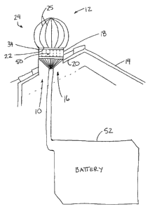
Referring to the accompanying figures there is illustrated a generator
device generally indicated by reference numeral 10. The device 10 is
particularly
suited for use with a roof top mounted ventilator 12 of the type which is
typically used
for mounting on a roof 14 of a building for communication through a roof
opening 16
therein.
The ventilator 12 includes a tubular base 18 in the form of a cylindrical
sleeve which is received through the roof opening 16 and which supports a
sealing
flange 20 spanning radially outwardly therefrom at a perimeter of the sleeve
for
sealing engagement with the surrounding roof. An upper edge 22 of the
cylindrical
sleeve forming the base 18 is overlapped by a ventilating turbine 24 which is
rotatably
supported on the base 18 which is fixedly supported on the roof top. The
turbine 24
comprises a barrel shaped member having a plurality of vanes 25 about the
circumference thereof which are oriented to capture wind to drive rotation of
the
CA 02621199 2008-02-06
7
turbine in response to a horizontal wind blowing across the turbine. The vanes
25
also function to draw a ventilating air current through the tubular base 18
for
ventilating the space below the roof.
The turbine 24 includes a cylindrical collar 26 at the base thereof which
is slightly larger in diameter than the sleeve forming the base 18 for
overlapping the
upper edge 22 of the base as it extends downwardly over the base about a full
periphery of the base. A domed enclosure is formed above the collar 26 with
slotted
openings therein in alignment with the respective vanes 25 to form a plurality
of
scoops which gather the wind and drive rotation of the turbine. The vanes 25
are
oriented in a common direction of rotation in relation to the central axis of
rotation of
the turbine.
The turbine 24 is supported on a central shaft 28 which is received
within a cup 30 at the bottom end of the shaft which is supported in fixed
relation to
the base 18 by a plurality of spokes 32 fixedly spanning between the cup 30
supporting the shaft therein on the peripheral wall 34 of the base. The
turbine is
rotatably supported on the shaft by a top bearing 36 rotatably receiving the
top end of
the shaft therein at the top end of the domed enclosure forming the turbine. A
central
bearing 38 is rotatably supported about the shaft to locate the shaft
centrally in
relation to the cylindrical collar 26 of the turbine by a plurality of
respective spokes 40
spanning between the central bearing 38 and the collar 26.
Although various embodiments of the present invention are shown and
described herein, in general in all embodiments, the device 10 comprises a
coupling
mechanism arranged to be coupled between rotation of the turbine and at least
one
generator 50 having an input shaft rotated by the coupling mechanism in
response to
rotation of the turbine to produce electrical power at the generator which
charges a
CA 02621199 2008-02-06
8
battery 52 connected thereto. Electrical power generated by the generators 50
and
stored in the battery 52 can then be used as supplemental power to homes and
other
buildings and the like.
Turning now more particularly to Figures 1 through 9, a first embodiment
of the device 10 will now be described in further detail. In this instance a
plurality of
the generators 50 are provided at circumferentially spaced positions about the
base
18 of the ventilator. Each generator comprises a housing which is generally
cylindrical
in shape having dimensions which are narrow in diameter while being generally
elongate in height to span substantially a height of the base 18. The
generators are
supported on an inner side of the peripheral wall 34 of the base. The input
shaft at the
top end of each generator mounts a wheel 54 thereon which is arranged for
selective
engagement with the turbine to rotate the wheel and the input shaft upon which
it is
supported for driving the respective generators 50.
The upper edge of the sleeve forming the base 18 of the ventilator
includes a plurality of cut-outs or openings 56 formed therein at
circumferentially
spaced positions about the sleeve of the base for alignment with the wheels 54
respectively. Each opening includes a bottom edge which is spaced downwardly
from
the upper edge of the base while a portion of the base spans above the opening
56 to
define a continuous peripheral rim on the base above the openings 56 spaced
therebelow.
Each generator includes an integral gear reduction coupling the input
shaft to the driven components of the generator. Each generator further
includes a
clutch mechanism which operates the respective wheel 54 for selectively
disengaging
the wheel 54 either from the turbine or from the generator as required. The
clutches
which control each of the respective generators and engagement of the
respective
CA 02621199 2008-02-06
9
wheels permit some of the wheels and respective generators to be disengaged
responsive to low velocity rotations of the turbine resulting from low wind
speeds so
as to operate the turbine at the greatest efficiency. Furthermore the
ventilator is
arranged to be permitted to continue to perform its ventilating function.
The device according to the first embodiment further includes an annular
member 57 which is arranged to be supported within the cylindrical collar 26
to line
the collar with a material having a high coefficient of friction on its
surface which is
engaged by the wheels 54 to ensure good frictional contact between the
periphery of
the wheels and the turbine, thereby preventing any relative slippage
therebetween.
The device further includes a shield 58 which is supported annularly
within the interior of the domes portion of the turbine in the form of a wall
which
projects radially inwardly and upwardly from the collar 26 to provide a roof
which
spans overtop of the circumferentially spaced generators therebelow and to
accordingly protect the generators from the elements. The electrical power
outputs of
all of the generators are connected commonly to the battery 52.
In further embodiments the wheels 54 may have different diameters or
different power ratings of generators may be provided, or yet further
different gearing
ratios may be provided between the wheels and the respective generators so
that a
turning ratio of some of the generators relative to the turbine is different
than others so
that generators having the most desirable turning ratio relative to the
turbine can be
selected to be engaged with the turbine for a particular wind speed while the
other
remaining generators may optionally be disengaged for optimal efficiency.
Engagement and disengagement of the wheels can also be controlled remotely.
In a further embodiment shown schematically in Figure 10, a
replacement shaft 70 may be provided which is fixed for rotation with the
turbine
CA 02621199 2008-02-06
relative to the base. The spokes spanning between the shaft and the collar of
the
turbine are accordingly fixed relative to the shaft and turbine, and the shaft
is instead
rotatably supported within the cup connected to the base of the ventilator by
respective spokes. The shaft in this instance preferably has a stepped
diameter which
5 reduces from an upper portion having a first prescribed diameter to a lower
portion
having a second prescribed diameter which is less than the first prescribed
diameter.
The shoulder formed between the upper and lower portions thus defines an
annular
end face which is engaged upon a thrust bearing 72 which carries the weight of
the
turbine thereon for rotatably supporting the turbine on the base. The lower
portion of
10 the shaft can thus be extended in length to extend downwardly into a roof
opening
where the replacement shaft can be connected directly to the input shaft of
the
generator for producing electrical power which is fed to the battery 52 as in
the
previous embodiment.
The device described herein can be used to produce electricity for all
types of uses. The electricity produced would be fed to and stored in
batteries which
could be used to subsidize the present commercial source, for use in general
for
appliance, equipment for tools and in particular for emergency backup use in
the
event or prolonged periods of commercial power outages. As few people at
present
have any backup sources of electricity, it would protect both them and their
plumbing
by maintaining furnace function during cold weather commercial source outages.
It
would also keep freezers, fridges and air conditioners operating during heat
waves,
thereby protecting food from spoiling and people from possibly heat exhaustion
or
stroke during prolonged outages of commercial electricity.
The device 10 described herein makes use of alternators and or
generators ranging in amperage from 1 to 1500 or more, which are permanently
CA 02621199 2008-02-06
11
attached but adjustable to the upper inside circumference of the roof top
turbine
housing. Cut outs in the housing provide an opportunity for wheels attached to
respective drive shafts to protrude through the housing and make contact with
the
rotating inside base of the turbine. The inside base can be modified to
accommodate
increased traction by adding a 1/2 to 4 inch wide continuous band over the
frame
support. The supporting frames may be repositioned upwards if this proves to
be
more advantageous. The alternators and/or generators will be equipped with
remote
control devices making it possible to employ them according to wind velocity;
that is
fewer would be engaged during low velocity periods while all may be employed
during
high velocity periods.
In the second embodiment when providing a replacement shaft, the
shaft diameter may be reduced in the order of 1/16 to 1/4 of an inch to allow
the
support bearing to support the shaft while still allowing the smaller diameter
lower
portion to pass through and be utilized by an alternator generator therebelow.
In this
instance, the typical 10 inch shaft provided on a commercially available and
conventional design of roof top ventilator, can be replaced with varying
lengths of
shafts, possibly up to 36 inches in length, to accommodate the alternator or
generator
utilization of same. An auxiliary drive wheel may also be supported on the
replacement shaft for driving the generator. The amperage of either will be in
accordance to the customer's preference and based on the average wind velocity
in
their area along with their electrical versus ventilation operations.
When fixing the shaft to the turbine, the top end of the shaft may be
secured to the top of the turbine through a hole made in the center of the
turbine just
large enough for the shaft to pass through operation choice. A threaded top of
the
shaft will be left exposed to accommodate a securing bolt. The shaft will be
inserted
CA 02621199 2008-02-06
12
into the top of the turbine matching the securing apparatus to the inside of
the housing
for subsequent riveting, studding or bolting in place. The shaft can also be
welded to
the turbine when it is certain that the shaft and turbine rotate perfectly
together.
When providing cut outs in the base for receiving a plurality of wheels at
circumferentially spaced positions therethrough, the cut outs or openings are
preferably provided within a range of approximately 13/16 of an inch or wider.
The cut
outs will be of various lengths to accommodate differing alternator or
generator drive
shaft wheels passing from the inside therethrough to outside to make contact
with the
rotating turbines overhanging collar which overlaps in the order of 13/16 of
an inch or
wider if modified such that the openings are accordingly located in alignment
with the
overlapped portion of the collar of the turbine.
Each alternator or generator has a metal and or plastic housing which
protects them from the weather, especially the moving components thereof. The
housings 60 form an enclosure on three sides of the respective generator while
the
peripheral wall of the base forms the remaining side to full enclose and
protect the
generator therein.
The material having a high coefficient of friction formed in an annular
member is secured along the inner surface of the collar of the turbine which
overlaps
the base by 13/16 of an inch or wider if modified. The annular member is made
of an
efficient tracking material, for example possibly scored aluminum. It will
extend
upward far enough to clear the top of the housing, then be bent to angle
towards the
center of the housing to the extent necessary to completely roof the
alternators/generators. As there is a half inch space between the housing and
the
rotating turbine, the strut support of the additional tracking band and roof
member will
be sufficiently deep enough to allow drainage for any moisture that might
otherwise
CA 02621199 2008-02-06
13
accumulate. All different sizes of rooftop ventilators can be modified in the
same way
from thin diameters of 18 to 36 inches for example, or larger such as
commercial
building rooftop ventilators, etc. Infinitely larger sizes of ventilator type
turbines can be
supported separately from a roof top on a windmill type support or tower for
example.
A much larger generator turbine could be produced measuring up to 100
meters in diameter or more. These would be mounted on a cement or steel
supported platform. Utilizing the same general design, principles and spirit
of the
afore explained, but on a much bigger scale, a much large alternator/generator
turbine would be produced measuring 100 meters in diameter or more. Personal
or
commercial buildings could be constructed beneath same, with the option of
incorporating some or all of the supporting pillars in their structure. These
would
accommodate alternators or generators of much greater amperage capacity.
Turning now more particularly to Figures 11 and 12, according to a
further embodiment of the device 10, an anemometer or wind force gauge 69 is
provided with a plurality of generator controls 71 for controlling the
generators 50
according to the first embodiment of Figures 1 through 9.
When providing a plurality of generators 50 which are supported
circumferentially about the peripheral wall 34 of the base 18 as in the
embodiment of
Figures 1 through 9, a preferred control and coupling mechanism between the
generators and the turbine 24 comprises one of the generator controls 71 being
associated with each generator for controlling engagement and disengagement of
the
respective wheel 54 of the generator with the annular member 57 on the turbine
upon
which the wheel rotates when engaged.
Each control 71 operates the respective generator independently of the
other generators for displacing the generator and the wheel supported thereon
CA 02621199 2008-02-06
14
relative to the base 18 between an engaged position in which the wheel engages
the
ventilating turbines such that the rotation of the turbine relative to the
base drives
rotation of the respective generator and a disengaged position in which the
respective
generator is disengaged from being driven by rotation of the turbine relative
to the
base. Each generator is thus supported on the base to be moveable relative to
the
base and the turbine rotatably supported thereon. A suitable spring mechanism
biases the generator into the disengaged position while a suitable motor is
provided
for displacing the respective generator into the engaged position upon
actuation
thereof by the respective generator control.
Initially all of the generators are in the disengaged position when there is
zero wind force as measured by the wind force gauge 69. The generator controls
are
arranged to be responsive to the wind force gauge to displace the generators
into the
engaged position responsive to increasing wind force as measured by the wind
force
gauge. At least some of the generator controls are responsive to different
wind forces
than other ones of the controls so that more generators are engaged with the
turbine
when the wind force is greater than when the wind force is reduced.
In a preferred operation, each generator control is operable to displace
the respective generator into the engaged position responsive to a wind force
measured by the wind force gauge which is greater than a previous one of the
generator controls so that with increasing wind force from zero force to a
prescribed
maximum force, all of the generators are sequentially displaced into the
engaged
position from the disengaged position. Similarly when the wind force decreases
from
the prescribed maximum to zero, all of the generators would accordingly be
sequentially displaced into the disengaged position.
As shown in Figures 11 and 12, the wind force gauge 69 comprises an
CA 02621199 2008-02-06
anemometer having a rotating portion 74 which rotates responsive to wind
forces to
increase its speed of rotation with increasing wind force. The anemometer or
wind
force gauge 69 also includes an output in the form of a dial 76 having a
needle 77
rotatably supported thereon which increases in angular deflection from a
starting point
5 with increasing wind force measured by the gauge. A plurality of switches 78
are
supported circumferentially about the dial for sequential engagement by the
needle 77
from the starting point as the wind force gradually increases. As the needle
77 passes
any one of the switches 78, the switch activates the associated generator
control to
actuate the associated generator into the engaged position. As the needle
passes the
10 switch again upon return to a zero indication on the dial of zero wind
force, the switch
causes the associated generator control to return the generator to the
disengaged
position. Each of the circumferentially positioned switches 78 corresponds
with a
respective one of the generator controls to operate a respective one of the
generators
50.
15 As described herein, the anemometer measures wind force, or speed.
As described herein, electric switches have been placed on the dial face,
which the
hand, or needle, switches on as it passes. When the velocity drops below this
reading, the needle reverses, turning the switch off as it passes.
Each anemometer would be equipped with as many switches as
necessary, to maximize the output of each generator. The dial face would be
enlarged
and the needle extended, to accommodate the number of generators being
serviced.
Turbines, much larger than roof top ventilators, would have many more
generators and therefore require many more switches.
Each switch turns on the electric supply to one or more motorized
components; which, in turn, provides sufficient force to move the generator,
or
CA 02621199 2008-02-06
16
generators, to the exact degree required, to engage its drive shaft wheel with
the
spinning turbine track. It then holds it at this precise position. When the
needle
switches the electricity off, the motorized component stops exerting force to
the
generator. A stationary spring affixed between the generator, on the inside
wall of the
turbine housing, aids in the immediate return the generator to its neutral
position.
The various generators are thereby engaged and disengaged, according
to the velocity that this electric supply switch is set at. This totally
automates the
system, maximizing all of the generators electrical output continuously.
In some embodiments, some of the generators are have a higher
amperage capacity than other ones of the generators such that some generators
would have less capacity to produce electricity than other ones of the
generators.
In other embodiments, a very large generator device could be built
according to the same design as the above but on a much larger scale, to be
mounted
on a cement or steel supported platform to maximize the capture of wind energy
at
low operating expense. In this instance, an infinitely larger duplicate
generator would
be comprised of a base supported on an elevated platform and a turbine
rotatably
supported on the base. The generator device comprises alternators or
generators
having an input shaft and being arranged to produce electricity when the input
shaft is
rotated and a coupling mechanism arranged to couple the input shaft of the
alternators or generators to the turbine thus capturing wind energy at low
operating
expense. Generator devices which are built on an infinitely larger scale can
be
arranged for the sole purpose of maximizing the harvesting of wind produced
electricity. All parts of the device described herein could be reproduced on
an
infinitely larger scale produce an infinity larger alternator/generator
turbine to be
mounted on an elevated platform.
CA 02621199 2008-02-06
17
It is understood when referring to generators herein, that any form of
generator or alternator can be used which generates electricity responsive to
a
mechanical input, typically in the form of a rotating shaft.
Since various modifications can be made in my invention as herein
above described, and many apparently widely different embodiments of same made
within the spirit and scope of the claims without department from such spirit
and
scope, it is intended that all matter contained in the accompanying
specification shall
be interpreted as illustrative only and not in a limiting sense.