Note: Descriptions are shown in the official language in which they were submitted.
CA 02621240 2013-03-18
Double crimping tool
The present invention relates to a double crimping tool for fastening an
electrical conductor
with insulation to a contact element. In particular, the invention relates to
a double crimping
tool for fastening an electrical conductor with insulation to a contact
element. The double
crimping tool comprises a front crimping unit with a front drive cam plate and
front crimping
stamps for forming a front press section in a region of a stripped end of the
conductor; a rear
crimping unit with a rear drive cam plate and rear crimping stamps for forming
a rear press
section in the region of the insulation of the conductor. The crimping stamps
of each crimping
unit comprise anvil surfaces that are directed towards each other, between
which anvil
surfaces is a receiving cross section for receiving the sections of the
contact element, which
sections are to be pressed together, with the conductor inserted therein. The
crimping stamps
are displaced by rotation of the drive cam plates in order to carry out the
pressing procedure
by narrowing the receiving cross section. Via levers, the two drive cam plates
are connected
to a shared force introduction element such that during the pressing procedure
at first
optionally the front or the rear drive cam plate is rotated by a predefined
initial pressing angle
so as to, in the associated press region, reduce the receiving cross section.
The other drive cam
plate is made to rotate only after the first drive cam plate has attained the
initial pressing
angle, in order to reduce the receiving cross section in the other press
region.
Such a tool is used for fastening an electrical conductor enclosed by an
insulation sheath,
which conductor can be a single- or multi-core wire, to a contact element, for
example a wire
end sleeve, a cable lug or a contact socket. By the double crimping tool both
an electrically
conductive connection between the conductor and the contact element is to be
established,
and an insulation section adjoining the stripped conductor end is to be
fastened to the contact
element by a pressing procedure. The crimping tool can be designed as a hand
tool or as a
machine-driven tool.
From US 3,713,322 a crimping tool for connecting a contact to a wire end is
known. This tool
uses two pairs of press pistons which in guide slots are displaced radially in
relation to a
1
CA 02621240 2013-03-18
receiving cross section so as to press the sleeve positioned in the receiving
cross section
together with the inserted wire end. In this arrangement initially the first
stamp pair with flat
anvil surfaces is brought to the contact sleeve in order to press said contact
sleeve against an
oval shape. During the further crimping process the stamp pair that is
positioned across the
first stamp pair is brought to the pre-pressed contact sleeve in order to
complete the crimping
process by curved anvil surfaces. The four press pistons are driven by a
shared cam ring,
wherein the advance of the individual press stamps is determined by the
radially changing
surface design on the inside of the cam ring. With this known crimping tool
only one
crimping process is possible in the region of the stripped end of the cable.
Furthermore,
during the crimping process a user of the hand tool has to exert considerable
forces.
US 5,415,015 shows a crimping tool by which in a single crimping process both
in the section
of the stripped electrical conductor and in the insulation section a press
connection with the
contact element to be connected can be established. To this purpose the
described manual
tool, on two opposing stamps, comprises two
la
CA 02621240 2008-03-03
- 2 -
differently designed anvil surfaces, situated axially one behind the other,
which
curing the crimping process act at the same time on the contact region and on
the
insulation region in order to deform the sleeve-shaped sections of the contact
pin. To
this effect the press stamps must be matched in a targeted manner to the shape
of the
contact sleeve. Consequently any processing of different cross sections is
largely
excluded. Furthermore, with the known crimping tool it is not possible to
establish
crimping connections that meet stringent safety requirements in the case of
permanent strain at the crimp position.
The standard MIL-C-22520/20, dated 19 March 1976, which requires the use of
four
crimping stamps that contact the circumference of the crimp section, in each
case
offset by 900, and that carry out the pressing procedure in pairs, describes
the design
of a crimp connection that meets such safety requirements and describes the
basic
design of a tool suitable to achieve this. The requirements of this standard
are, for
example, met by the crimping tool according to the above-mentioned US
3,713,322.
Therefore, when designing a crimping tool that conforms to the standard
mentioned,
the average person skilled in the art is thus limited in his/her freedom of
development
so that up to now there was little detectable scope for improvements.
WO 2004/021523 Al discloses a crimping tool by which the concurrent
establishment of a press connection in the section of the stripped conductor
end and
in the adjacent insulation section is to be made possible. To this effect two
crimping
units, arranged one behind the other, are provided, each comprising four
crimping
stamps which during the crimping process at the same time are radially
displaced
into the receiving cross section where they press the contact sleeve and the
conductor
together. Concurrent pressing together in the conductor region and in the
insulation
region requires extremely large forces, in particular at larger cross-
sections, which
forces can no longer be exerted by a user using a hand tool. The substantial
loads
encountered result in rapid wear of the press stamps. Furthermore, an
unfavourable
position displacement of the electrical conductor in the contact sleeve may
result
CA 02621240 2008-03-03
-3 -
when press forces act on the insulation region before the conductor has been
adequately fastened in the contact sleeve. Finally, the known crimping tool
does not
make it possible to process various cross-sections without the individual
press stamps
being changed.
DE 195 07 347 Cl describes press pliers for wire end sleeves. These press
pliers use
six press jaws that are swivellably held on bearing pins, and that, when a
ring-shaped
swivel lever is actuated, are swivelled into the cross section that receives
the wire
end sleeve in order to carry out the pressing procedure by the resulting
reduction in
cross section. However, these press pliers do not make it possible to
simultaneously
produce two crimp connections in axially successive sections and is
furthermore not
permissible if conductor ends are to be crimped, according to the above-
mentioned
standard, to wire end sleeves.
From DE 40 23 337 C1 a tool for crimping a double connection of a connector
with a
conductor on the one hand and an insulation on the other hand is known. The
tool
comprises a tool head that has a frame and a press jaw that is axially affixed
to the
frame, as well as a press jaw that is axially guided on the frame. The axially
guided
press jaw comprises at least two stamp plates that have work profiles, and by
a drive
is pressed against the axially fixed press jaw which in that location
comprises at least
two anvil plates that have work profiles. At least one of the anvil plates or
stamp
plates is swivellable, on the respective other anvil plate or stamp plate, on
an axis
that is arranged so as to be perpendicular in relation to the axis of
principal extension
S0 that another edge with a differently designed work profile becomes
effective when
the jaws are pressed together.
From DE 195 09 442 C2 crimping pliers for the manually actuated fastening of a
connector plug to a cable are known, in which four die inserts with several
crimp
nests are placed onto two opening jaws. The four crimp nests are arranged in
the die
inserts so as to be placed side by side, of which four crimp nests at least
one is
= CA 02621240 2013-03-18
arranged such that jamming the tension relief for the cable to be attached to
the connector
plug takes place on opposite sides of the die inserts. The solution known from
this printed
publication is, in particular, suitable for crimping connectors to ignition
cables.
From EP 1 598 906 A1 a crimping tool with a rotatable stamp is known, which on
its side
comprises four differently sized crimp profiles. The rotatable stamp is
pressed against a fixed
press jaw that comprises two differently sized crimp nests. By rotating the
rotatable stamp,
one of the four different crimp profiles can be selected, wherein in each case
the selected
crimp profile is opposite the suitable one of the two crimp nests.
It is thus the object of the present invention to provide an improved crimping
tool, by which
in a single crimping process a double crimp connection in axially offset
regions of a contact
element can be produced in order to connect both the stripped conductor end
and the end
region of the insulation to the contact element. In cross sections that are
usual for crimp
connections, this is to be possible with the exertion of little force that can
be provided by a
user in single-handed manual operation, so that the crimping tool can also be
designed in the
form of a hand tool. The crimping tool should be able to be adapted to various
contact
element types, contact element sizes and cable cross-sections without much
effort. Finally, the
crimping tool should make it possible, at least in the section of the stripped
wire end, to
generate a crimp connection that complies with the MIL-standard.
This object is met by a double crimping tool for fastening an electrical
conductor with
insulation to a contact element. The double crimping tool comprises a front
crimping unit with
a front drive cam plate and front crimping stamps for forming a front press
section in a region
of a stripped end of the conductor; a rear crimping unit with a rear drive cam
plate and rear
crimping stamps for forming a rear press section in the region of the
insulation of the
conductor. The crimping stamps of each crimping unit comprise anvil surfaces
that are
directed towards each other, between which anvil surfaces is a receiving cross
section for
receiving the sections of the contact element, which sections are to be
pressed together, with
the conductor inserted therein. The crimping stamps are displaced by rotation
of the drive cam
plates in order to carry out the pressing procedure by
4
= CA 02621240 2013-03-18
narrowing the receiving cross section. Via levers, the two drive cam plates
are connected to a
shared force introduction element such that during the pressing procedure at
first optionally
the front or the rear drive cam plate is rotated by a predefined initial
pressing angle so as to, in
the associated press region, reduce the receiving cross section. The other
drive cam plate is
made to rotate only after the first drive cam plate has attained the initial
pressing angle, in
order to reduce the receiving cross section in the other press region.
To this effect on the double crimping tool a front crimping unit and a rear
crimping unit are
each operated by their own drive cam plates, wherein both cam plates are
connected, by
levers, to a shared force introduction element so that in the pressing
procedure first one drive
cam plate is rotated by a predetermined initial pressing
4a
CA 02621240 2013-03-18
angle, and only thereafter is the second drive cam plate set into motion in
order to also crimp
the insulation region. Depending on the embodiment it is possible in this
arrangement for the
crimping process in the conductor region to be partly or almost fully
completed before the
crimping process is carried out in the insulation region. As a result of this
measure the forces
required are considerably reduced. Actuation of the drive cam plates can,
however, also take
place in the reverse sequence so that crimping takes place only in the rear
press region,
followed by crimping in the front press region.
Furthermore, the required drive force can be reduced in that a force-path
conversion takes
place by the toggle-lever technique that is known per se.
Preferably, the front crimping unit, by which the crimp connection is
established in the
stripped conductor section, comprises four crimping stamps that are slidable
radially in
relation to the receiving cross section. The front crimping unit is in this
way preferably
designed according to the above-mentioned MIL-standard.
In order to achieve a good crimp result in the insulation region while
exerting little in the way
of force, instead several crimping stamps are used in the rear crimping unit,
which crimping
stamps are swivellably held, with their anvil surfaces tangentially swivelling
into the
receiving cross section. For practical implementation of such a design,
reference is made to
the cited DE 195 07 347 C1.
Further preferred embodiments may include a crimping tool, wherein when the
initial pressing
angle has been reached, the front and the rear drive cam plates are together
rotated by a
predetermined angle.
Further preferred embodiments may also include a double crimping tool, wherein
a front end
stop is formed by a front adjusting element which when an intermediate angle
has been
reached stops any further rotation of the front drive cam plate, while the
rear drive cam plate
continues to be rotated until a rear end stop that is formed by a rear
adjusting element is
reached.
5
CA 02621240 2013-03-18
Further preferred embodiments may also include a double crimping tool, wherein
in each case
one of the adjusting elements is arranged on the front and/or on the rear
crimping unit, by
which adjusting element the effective cam travel of the front and/or of the
rear drive cam plate
are/is variable so that the crimp dimension can be set.
Further preferred embodiments may also include a double crimping tool, wherein
the
introduction of force is by way of a drive lever that is connected to a front
and a rear toggle
lever which in turn drive the front or rear drive cam plates respectively.
Further preferred embodiments may also include a double crimping tool, wherein
the front
crimping unit comprises four front crimping stamps that are radially slidable
in relation to the
receiving cross section and that in each case are arranged so as to be offset
by approximately
900 so that their anvil surfaces oppose each other in pairs.
Further preferred embodiments may also include a double crimping tool, wherein
the rear
crimping stamps of the rear crimping unit are swivellably held and when
activated by the rear
drive cam plate their anvil surfaces swivel tangentially into the receiving
cross section.
Further preferred embodiments may also include a double crimping tool, wherein
the double
crimping tool is designed as a hand tool that is suitable for single-handed
operation.
Further preferred embodiments may also include a double crimping tool, wherein
the front
and the rear crimping unit are arranged between two retaining plates that are
connected to one
of the handles of the hand tool, while the other handle is connected to a
drive lever which in
turn establishes an effective connection with the drive cam plates.
Further preferred embodiments may also include a double crimping tool, wherein
there is an
activation detent which makes it possible to open the hand tool only after a
predetermined end
position has been reached.
5a
. CA 02621240 2013-03-18
Further preferred embodiments may also include a double crimping tool, wherein
the double
crimping tool further comprises a machine drive.
Details, advantages and embodiments of the present invention are stated in the
following
description of a preferred embodiment with reference to the drawing. The
following are
shown:
Fig. 1 a perspective view of a double crimping tool in the form of
a hand tool;
5b
CA 02621240 2008-03-03
- 6 -
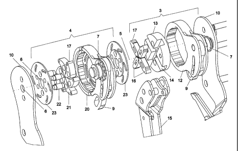
Fig. 2 an exploded view of the tool head of the hand tool shown in Fig.
1.
The double crimping tool, according to the invention, shown in Fig. 1 is
designed as
a hand tool that is suitable for single-handed operation. To this effect this
hand tool
in the conventional manner first comprises two handles 1 that for improved
ergonomics can additionally comprise plastic grips formed to fit the hand.
The actual double crimping tool is arranged in the tool head 2. It comprises a
front
crimping unit 3 and a rear crimping unit 4. The two crimping units are
arranged
axially one behind the other in relation a workpiece axis 5. Along the
workpiece axis
5 in a central receiving cross section 6, which when the tool is in its open
position
continues in the two crimping units, a contact element and an electrical
conductor
(not shown) to be affixed to said contact element are inserted.
Preferably, each crimping unit comprises its own adjusting element 7, by way
of
which various crimp dimensions (cross section of the longitudinal section that
is to
be pressed by the respective crimping unit) can be set. The way the adjusting
elements 7 function will be explained in detail further below with reference
to a
special embodiment.
Furthermore, an activation detent 8 can be built into the hand tool, which
activation
detent 8, following commencement of the crimping process, only allows the tool
to
be opened again after the end position of the crimping units has been reached.
This
ensures that the desired final dimension during crimping is adhered to in each
case.
In the embodiment shown, furthermore, two toggle levers 9 are provided, which
are
used for the transmission of force from the handles 1 to the crimping units 3,
4.
CA 02621240 2008-03-03
- 7 -
Fig. 2 shows an exploded view of the tool head with the essential components
of the
crimping tool. The individual parts are enclosed between two retaining plates
10,
which can be designed as an extension of one handle 1.
The front crimping unit 3 comprises a front drive cam plate 12, whose inside
comprises a profiled surface so that the resulting distance between the
workpiece
axis 5 and this surface varies. In the front drive cam plate 12 a guiding disc
13 with
four cross-shaped guide slots 14 is inserted. The guiding disc 13 is arranged
so as to
be stationary in relation to the retaining plates 10, while the front drive
cam plate 12
is rotatable relative to the guiding disc 13. The drive force required for
this rotation is
introduced by way of the toggle lever 9 and a shared drive lever 15.
The front crimping unit 3 is further associated with four front crimping
stamps 16
that are guided in the guide slots 14. Fig. 2 shows the crimping stamps in
their closed
state in which their inward-facing anvil surfaces are in close proximity to
each other.
In the open state of the tool, the crimping stamps unblock the receiving cross
section
6 in order to receive the contact element with the inserted electrical
conductor. In
order to move the front crimping stamps to their home positions, spring
elements
(not shown in the drawing) are arranged in a manner that is known per se.
The actuation surfaces 17 of the front crimping stamps 16, which actuation
surfaces
17 are situated radially outward in relation to the receiving cross section 6,
come to
rest against the cam surface of the front drive cam plate 12, and due to the
surface
design are moved radially inward during rotation of the front drive cam plate
12 so as
to press the stripped section of the conductor in the contact element.
The rear crimping unit 4 comprises a rear drive cam plate 20 with the toggle
lever 9
that acts thereon, which toggle lever 9 in turn is driven by the drive lever
15.
Furthermore, there are six rear crimping stamps 21 whose actuation surfaces 17
rest
against the profiled interior surface of the rear drive cam plate 20.
CA 02621240 2008-03-03
- 8 -
The rear crimping stamps 21 are swivellably held by carrying lugs 22 that in
turn are
fastened to supporting plates 23. During actuation of the rear drive cam plate
20,
which actuation takes place by rotation on the workpiece axis 5, each rear
crimping
stamp 21 is swivelled on its carrying lug 22 so that the inward anvil surfaces
of the
rear crimping stamps 21 tangentially engage the receiving cross section 6 in
order to
narrow it, as a result of which the longitudinal section, positioned in that
location, of
the contact element is pressed around the insulation of the electrical
conductor. This
results in a hexagonal profile formation in the insulation region. In the case
of
modified embodiments, it is also possible to use a greater or lesser number of
rear
crimping stamps; however, the use of six rear crimping stamps has been shown
to be
advantageous.
The supporting plates 23 in conjunction with spring units (not shown) at the
same
time are used to achieve forced return travel of the rear crimping stamps 21.
Both in the front crimping unit and in the rear crimping unit the drive forces
are
transmitted by way of the above-mentioned toggle levers 9. Said toggle levers
9, as
far as their length and their position of coupling to the drive cam plates 12,
20 on the
one hand, and to the drive lever 15 on the other hand are concerned, are
designed
such that when the hand tool is actuated, at first only the front drive cam
plate 12 is
made to rotate. Only after a predetermined press angle of, for example, 15
has been
covered, does the drive force act upon the rear drive cam plate 20 so that the
latter is
also made to move. The initial pressing angle can, preferably in the region
between
10 and 30 , be selected such that at least partial pressing in the front
crimping unit
between the stripped conductor end and the contact element is achieved or that
this
pressing procedure is already considerably advanced. Depending on the
embodiment,
in the subsequent press step both drive cam plates are rotated at the same
time over a
determined angle section, or at this stage largely only rotation of the rear
drive cam
CA 02621240 2008-03-03
- 9 -
plate 20 takes place to establish the crimp connection between the insulated
conductor section and the contact element.
In the embodiment shown on each drive cam plate there is an already mentioned
adjusting element 7, by which in each crimping unit the cross-sectional
dimension
can be set, which cross-sectional dimension is to be achieved on completion of
the
crimping process. In the embodiment shown a cam is used as an adjusting
element 7,
by way of which cam the cam travel for the respective drive cam can be set. In
this
way the effective length of the engaging lever is changed, wherein in each
case on
completion of the set cam travel any further rotation of the drive cam plate
is stopped
so that the associated crimping stamps do not penetrate any further into the
receiving
cross section.
By the separate settability the double crimping tool can easily be adjusted to
various
cross-sectional dimensions, so that with a single tool various contact
elements and
conductor cross sections can be processed.
The settability also makes possible any re-setting of the crimp dimensions,
which re-
setting becomes necessary due to wear and tear.
In modified embodiments it is, for example, also possible to use a revolver
adjusting
stop for setting the crimp end dimension.
, CA 02621240 2008-03-03
- 10 -
List of reference characters
1 -Handle
2 - Tool head
3 - Front crimping unit
4 - Rear crimping unit
5 - Workpiece axis
6 - Receiving cross section
7 - Adjusting element
8 - Activation detent
9 - Toggle lever
10 - Retaining plates
12 - Front drive cam plate
13 - Guiding disc
14 - Guide slots
15 - Drive lever
16 - Front crimping stamps
17 - Actuation surfaces
20 - Rear drive cam plate
21 - Rear crimping stamps
22 - Carrying lug
23 - Supporting plates