Note: Descriptions are shown in the official language in which they were submitted.
CA 02621412 2008-03-05
WO 2007/032838
PCT/US2006/031380
STANDOFF ATTACHMENT WITH INTERNAL NUT
BACKGROUND OF THE INVENTION
This invention relates generally to an improved standoff attachment
of the type designed for mounting onto a substrate, for use in supporting
hardware items such as conduits or cables and the like with respect to the
substrate. More specifically, this invention relates to an improved standoff
attachment having an internal floating nut mounted substantially at a distal
or free end of an elongated standoff post, wherein the internal nut
facilitates
subsequent assembly with a threaded fastener such as a bolt or screw.
Standoff attachments are well known for use in a variety of aerospace,
marine and automotive applications for supporting items such as electrical,
pneumatic and/or hydraulic service lines and the like on a substrate. A
typical standoff attachment comprises a base structure adapted for secure
mounting onto the substrate, in combination with an elongated standoff post
projecting outwardly a short distance from the base structure. The standoff
post carries a threaded nut adapted for thread-in engagement with a mating
fastener such as a suitable bolt or screw used for mounting and supporting
the item, such as an electrical wiring bundle or the like, generally at a
distal
or free end of the standoff post. In one preferred configuration particularly
suited for use with thin-walled and/or composite material substrates, the base
structure of the standoff attachment is adapted for adhesive bonded
mounting onto the substrate thereby avoiding the need to form one or more
holes in the substrate. See, for example, U.S. Patent 4,668,546, and
adhesive bonded standoff attachments available from Click Bond, Inc. of
Carson City, Nevada under product part numbers CB3001, CB3004, CB4001
and CB 4002.
In the past, the threaded standoff nut has been tightly locked or
anchored in position on or within the standoff post, as by co-molding the
threaded nut within a standoff post formed from a thermoplastic or other
SUBSTITUTE SHEET (RULE 26)
PSI-48835
PCT APP
CA 02621412 2008-03-05
WO 2007/032838
PCT/US2006/031380
-2-
moldable material. Such rigid nut installation undesirably increases the risk
of cross-threaded engagement by the associated bolt or screw, particularly
in view of the fact that the bolt or screw is commonly installed by means of
a power tool. Unfortunately, a cross-threaded coupling can be difficult to
disassemble, and, upon disassembly, difficult or impossible to re-assemble
without replacing the threaded standoff nut. In this regard, nut cross-
threading can be a major problem when one or more standoff couplings are
disassembled to permit separation of a wiring grid or network or the like from
the substrate in the course of routine and/or scheduled maintenance
procedures, followed by re-assembly of the standoff coupling components.
By contrast, quick and easy, cost-efficient mounting of the standoff nut
in a floating manner at the distal end of the standoff post, to accommodate
a minor degree of axial and rotational movement relative to the standoff post,
substantially without risk of the standoff nut separating from the standoff
post, has not been achieved.
The present invention relates to an improved standoff attachment,
particularly of the type adapted for adhesive bonded mounting onto a
selected substrate, and including an internal threaded nut for subsequent
assembly with an associated bolt or screw, wherein the threaded nut is
captured and retained substantially at a distal end of the standoff post and
in a floating manner, i.e., in a manner accommodating a minor degree of
axial and rotational displacement.
SUMMARY OF THE INVENTION
In accordance with the invention, an improved standoff attachment is
provided for secure, preferably bonded fixation to a selected substrate, and
includes an elongated standoff post having a floating internal nut carried
generally at a distal or free end thereof. The floating internal nut is
adapted
to receive and engage a mating fastener used to mount a support element
such as a line clamp or the like substantially at the distal end of the stand-
off
SUBSTITUTE SHEET (RULE 26)
PSI-48835
PCT APP
CA 02621412 2013-09-30
WO 2007/032838
PCT/US2006/031380
-3-
post. The floating internal nut accommodates a minor degree of axial and
rotational displacement relative to the standoff post, thereby facilitating
proper threaded engagement with the mating fastener particularly by means
of a power tool, with minimal risk of improper cross-threading.
In the preferred form, the standoff post comprises a generally tubular
structure projecting from an enlarged base having a size and shape for
secure bond-on attachment to the substrate. The tubular standoff post
defines an internal hollow slotted channel of noncircular cross-section which
extends from a proximal end of the post at the base, and terminates at the
post distal end in a radially in-tumed flange defining a comparatively smaller
cross-section fastener-receiving port. The internal nut includes a peripheral
rib sized and shaped for axial slide-fit reception into the slotted channel at
an
inboard side of the distal end flange, wherein this rib mates with the slotted
channel shape to accommodate a minor degree of nut rotation while
precluding substantial nut rotation. An elongated slotted plug is secured
- within the slotted channel at an inboard side of the nut and functions to
retain
the nut preferably with a minor degree of axial freedom at a position
interposed axially between the plug and the distal end flange.
In use, the standoff attachment is adapted for quick, easy, and secure
adhesive bonded fixation onto a selected substrate as by means of a fixture
of the general type disclosed in U.S. Patent 4,668,546.
Such fixture generally comprises an outer frame having
a connector flange carrying a pressure sensitive adhesive or the like for
temporary adherence to the substrate, an inner frame carrying the standoff
attachment, and a plurality of spring tabs or spokes extending between the
inner and outer frames. With the standoff attachment supported by the inner
frame, a selected curable bonding agent is applied to the underside of the
attachment base, followed by pressed and seated adherence of the outer
frame connector flange against the substrate. In this position, the inner
frame is displaced toward the substrate to press the attachment base against
the substrate, and to shift the spring tabs over-center for applying a
positive
SUBSTITUTE SHEET (RULE 26) PSI-48835
PCT APP
CA 02621412 2008-03-05
WO 2007/032838
PCT/US2006/031380
-4-
force retaining the attachment base firmly against the substrate for the
duration of a bonding agent cure time. After the bonding agent has cured,
the fixture can be stripped from the standoff attachment.
Thereafter, a mating fastener such as a bolt or screw can be
threadably engaged with the floating nut at the distal end of the standoff
post,
for purposes of mounting one or more selected support elements thereto. In
one preferred form, the support element comprises a clamp such as a P-type
clamp used for supporting elongated conductive cables or wiring bundles or
the like.
Other features and advantages of the present invention will become
apparent from the following more detailed description, taken in connection
with the accompanying drawing which illustrate, by way of example, the
principals of the present invention.
BRIEF DESCRIPTION OF THE DRAWINGS
The accompanying drawings illustrate the invention. In such drawings:
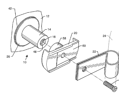
FIGURE 1 is a perspective view of a standoff attachment constructed
in accordance with the invention and shown mounted onto a supporting
= substrate, and depicted in exploded relation with a threaded fastener for
securing an illustrative line clamp support bracket and related line clamp
thereto;
FIGURE 2 is an enlarged front elevation view of the standoff
attachment in exploded relation with an exemplary mounting fixture;
FIGURE 3 is an enlarged vertical sectional view of the standoff
attachment, taken generally on the line 3-3 of FIG. 2;
FIGURE 4 is an exploded and partially fragmented perspective view
of the standoff attachment of FIG. 3;
FIGURE 5 is an enlarged horizontal vertical section taken generally on
the line 5-5 of FIG. 3;
SUBSTITUTE SHEET (RULE 26)
PSI-48835
PCT APP
CA 02621412 2008-03-05
WO 2007/032838
PCT/US2006/031380
-5-
FIGURE 6 is an enlarged horizontal vertical section taken generally on
the line 6-6 of FIG. 3; and
FIGURE 7 is an enlarged vertical sectional view showing the standoff
attachment mounted onto the substrate, and further depicting the threaded
fastener, line clamp support bracket and related line clamp assembled
therewith.
DETAILED DESCRIPTION OF THE PREFERRED EMBODIMENT
As shown in the exemplary drawings, a standoff attachment referred
to generally in FIGURE 1 by the reference numeral 10 is provided for
mounting onto a selected substrate 12. The standoff attachment includes an
elongated standoff post 14 having an internal threaded nut 16 mounted
generally at a distal or free end thereof, and in a floating manner to
accommodate a minor degree of axial and/or rotational displacement.
The improved standoff attachment 10 of the present invention is
particularly designed for use in a variety of aerospace, marine and
automotive applications for supporting items such as electrical, pneumatic
and/or hydraulic service lines and the like on a substrate, such as a
supporting panel or hull or other frame component. In the preferred form, the
standoff attachment 10 is adapted for secure and stable adhesive bonded
fixation onto the substrate 12, without requiring formation of any mounting
hole or holes in the substrate. Accordingly, the standoff attachment is
particularly suitable for use with thin-walled and/or non-metal or composite
material substrates.
In general terms, the floating nut 16 on the standoff post 14 is adapted
for threaded reception of and engagement with a mating fastener 18, such
as an appropriately sized bolt or screw used for mounting one or more
support elements substantially at the distal end of the standoff post 14.
FIGURES 1 and 7 shown illustrative support elements in the form of a line
clamp support bracket 20 for providing a stable foundation to support a P-
SUBSTITUTE SHEET (RULE 26)
PSI49835
PCT APP
CA 02621412 2008-03-05
WO 2007/032838
PCT/US2006/031380
-6-
type line clamp 22 or the like which is used in turn for carrying an elongated
structure such as one or more conductive cables or a wiring bundle 24 or the
like relative to the substrate. Persons skilled in the art will recognize and
appreciate that the threadably engaged nut 16 and fastener 18 may be used
for securing any of a wide variety of different support elements at the distal
end of the standoff post 14.
In accordance with a primary aspect of the invention, the floating nut
16 is quickly, easily, and properly engaged by the mating fastener 18,
substantially without risk of an improper cross-threaded engagement and/or
associated jamming of the threaded coupling and/or undesirable stripping of
the internal threads within the nut 16. Such proper engagement between
these components 16, 18 is facilitated despite conventional use of a power
tool (not shown) for threadably engaging the fastener 18 with the nut 16. The
floating nut 16 accommodates minor albeit sufficient axial and/or rotational
displacement relative to the standoff post 14 to achieve the desired proper
threaded engagement with the fastener 18. However, significant axial and/or
rotational nut displacement relative to the post 14 is substantially
prevented.
As shown in the illustrative drawings in accordance with one preferred
form of the invention, the improved standoff attachment 10 generally
comprises an enlarged base 26 carrying the standoff post 14. These
components are constructed from a relatively stiff and rigid or sturdy
material
suitable for affixation to the substrate 12 at a selected point thereon. In
this
regard, in a preferred form, the attachment base 26 and associated post 14
are constructed from a selected thermoplastic material such as
polyetheretherketone (PEEK), polyetherimide (PEI), or
polyetherketoneketone (PEKK), suitable for adhesive bonded mounting onto
the substrate 12. The illustrative drawings show the base 26 having a
circular or disk-shaped configuration defining a relatively large underside
surface 28 for adhesive bonded attachment to the substrate 12.
More particularly, as viewed in FIG. 2, a disposable fixture 30 may be
provided for use in secure adhesive bonded mounting of the standoff
SUBSTITUTE SHEET (RULE 26)
PSI-48835
PCT APP
CA 02621412 2013-09-30
WO 2007/032838 PCT/US2006/031380
-7-
attachment 10 to the substrate 12. The disposable fixture 30 generally
conforms with the fixture shown and described in U.S. Patent 4,668,548.
Specifically, the disposable fixture
30 comprises an outer frame 32 having one or more connector flanges 34
each carrying a pressure sensitive adhesive 36 or the like for temporary
adherence to the substrate. The outer frame 32, which may be constructed
from a lightweight molded plastic material, is joined by a plurality of
inwardly
radiating spring tabs or spokes 38 to an inner frame 40 carrying the standoff
attachment 10 as by press-fit engagement of the standoff post 14 into a
1 0 central bore 41 formed in the inner frame 40 with the enlarged base 26
bearing against a lower end of the inner frame. In an initial position as
viewed in FIG. 2, the spring tabs 38 extend radially inwardly and axially from
the outer frame 32 to support the inner frame 40 in a position spaced or
retracted a short distance above the plane of the pressure sensitive adhesive
36 on the connector flanges 34.
A selected curable bonding agent 42 (FIGS. 1 and 2) is applied to the
underside of the standoff attachment base 26, followed by pressed and
seated adherence of the outer frame connector flanges 34 against the
substrate 12. The pressure sensitive adhesive 36 retains the fixture 30 in
place on the substrate. The inner frame 40 is then displaced toward the
substrate 12 to press the attachment base 26 against the substrate, thereby
firmly pressing the bonding agent 42 on the base 26 against the substrate.
This displacement is accompanied by shifting of the spring tabs 38 over-
center thereby applying a positive force urging and retaining the attachment
base 26 firmly against the substrate 12 for the duration of a bonding agent
cure time. After the bonding agent 42 has cured, the fixture 30 can be
stripped from the standoff attachment 10, to leave the attachment 10 on the
substrate (as viewed in FIG. 1).
The thus-mounted standoff attachment is oriented with the standoff
post 14 protruding a short distance from the substrate '12. As shown best in
FIGS. 3-7, this post 14 has a generally tubular and hollow configuration
SUBSTITUTE SHEET (RULE 26)
PSI-48535
PCT APP
CA 02621412 2008-03-05
WO 2007/032838
PCT/US2006/031380
-8-
incorporating a slotted internal channel 44 extending from an inboard or
proximal end thereof at the base 26, and terminating at the distal or free end
of the post whereat a radially in-turned flange 46 (FIG. 3) defines an open
fastener-receiving port 48 of comparatively smaller cross sectional size. As
shown (FIGS. 5-6), a preferred configuration for the slotted channel 44
comprises a generally circular bore lined by a plurality of longitudinally
extending and radially enlarged elongated grooves 50, with the exemplary
cross sectional drawings showing four grooves 50 formed at equi-angular
intervals. By contrast, the fastener-receiving port 48 has a circular shape
and a diametric size smaller than a diametric size defined by the grooves 50.
The internal nut 16 is slide-fitted into the slotted internal channel 44
of the standoff post 14, to a position disposed substantially at an inboard
side
of the in-turned flange 46 at the post distal end. The preferred nut geometry
comprises an internally threaded, generally cylindrical body component
joined at an axially upper margin with a keyed rib 52 defining a plurality of
radially outwardly projecting keys sized for respective slide-fit reception
into
the enlarged grooves 50 defining the slotted channel 44. The individual ribs
are sized to accommodate a minor degree of rotational freedom for the nut
16 relative to the slotted channel 44 in the standoff post 14, but otherwise
prevent substantial nut rotation relative to the post.
A slotted plug 54 has an elongated shape defining a non-circular cross
section sized for slide-fit reception into the slotted channel 44, subsequent
to slide-fit installation of the nut 16. In this regard, the cross sectional
shape
of the plug 54 matingly or substantially matingly conforms with the shape of
the slotted channel 44, whereby the plug 54 effectively supports and retains
keyed rib 52 on the nut 16 substantially at the distal end of the standoff
post
14, preferably with a minor degree of axial freedom movement between an
upper end of the plug 54 and an inboard face of the post flange 46. As
shown, the body component of the nut 16 is sized for slide-fit reception into
an otherwise open upper end of the plug 54.
SUBSTITUTE SHEET (RULE 26)
PSI-48835
PCT APP
CA 02621412 2008-03-05
WO 2007/032838
PCT/US2006/031380
-9-
In addition, as shown, the plug 54 has a lower end terminating
substantially at the plane of the underside surface 28 on the base 26. In the
preferred form, the plug U. is secured in place as by an ultrasonic weld 56
or the like. Persons skilled in the art will appreciate, however, that
alternative
securement methods may be used, including but not limited to adhesive
materials and press-fitted engagement of the components.
With the standoff attachment 10 mounted onto the substrate 12, the
mating fastener 18 such as a bolt or screw can be threadably engaged with
the floating nut 16 at the distal end of the standoff post 14, for purposes of
mounting one or more selected support elements thereto. In one preferred
form as shown (FIGS. 1 and 7), the support element or elements may
comprise the line clamp support bracket 20 defining an underside boss 58
for seated engagement onto the distal end of the standoff post 14, and an
upper platform 60 for seated support of one or more additional support
elements such as the illustrative P-type line clamp 22 used for supporting
and retaining elongated structures such as the exemplary wiring bundle 24
or the like. Importantly, the floating nature of the nut mount at the distal
end
of the standoff post 14 accommodates rapid and accurate threaded coupling
between the fastener 18 and nut 16, with minimal risk of undesired cross-
threading, despite use of a power tool for component assembly. In addition,
the floating nature of the nut mount further accommodates a variety a nut
thread embodiments including split and/or out-of-round so-called lock nut
configurations. Moreover, upon tight threaded engagement of the fastener
18 with the nut 16, the in-turned flange 46 at the distal end of the standoff
post 14 effectively prevents the nut 16 from being axially separated from the
standoff post 14.
In a typical installation, multiple standoff attachments 10 are mounted
onto the substrate 12 and cooperatively support wiring bundles 24 or the like
that collectively define a complex wiring harness or grid carried by the
substrate. The fasteners 18 associated with a selected plurality of standoff
attachments 10 can be disassembled to accommodate and facilitate
SUBSTITUTE SHEET (RULE 26)
PSI-48835
PCT APP
CA 02621412 2013-09-30
WO 2007/032838
PCT/US2006/031380
-10-
separation of the wiring hamess from a localized region of the substrate in
the course of a required =maintenance and/or repair procedure. When the
maintenance activity is completed, the individual fasteners 18 can be re-
engaged with their respective standoff attachments 10 with minimal risk of
undesired component cross-threading.
Although various embodiments and alternatives have been described
in detail for purposes of illustration, various further modifications may be
made.
Accordingly, no limitation on the invention is intended by way of the
foregoing
description and accompanying drawings.
. .
SUBSTITUTE SHEET (RULE 26) PSI-48835
PCT APP