Note: Descriptions are shown in the official language in which they were submitted.
CA 02621428 2008-03-05
WO 2007/033346 PCT/US2006/035939
Arbitrary Resolution Change Downsizing Decoder
BACKGROUND
[0001] Digital video content is typically generated to target a specific data
format. A video data format generally conforms to a specific video coding
standard or a proprietary coding algorithm, with a specific bit rate, spatial
resolution, frame rate, etc. Such coding standards include MPEG-2 and
WINDOWS Media Video (WMV). Most existing digital video contents are coded
according to the MPEG-2 data format. WMV is widely accepted as a qualified
codec in the streaming realm, being widely deployed throughout the Internet,
adopted by the HD-DVD consortium, and currently being considered as a SMPTE
standard. Different video coding standards provide varying compression
capabilities and visual quality.
[0002] Transcoding refers to the general process of converting one
compressed bitstream into another compressed one. To match a device's
capabilities and distribution networks, it is often desirable to convert a
bitstream in
one coding format to another coding format such as from MPEG-2 to WMV, to
H.264, or even to a scalable format. Transcoding may also be utilized to
achieve
some specific functionality such as VCR-like functionality, logo insertion, or
enh,anced error resilience capability of the bitstream for transmission over
wireless
channels.
[0003] Fig. 1 shows a conventional Cascaded Pixel-Domain Transcoder
(CPDT) system, which cascades a front-end decoder to decode an input bitstream
witll an encoder that generates a new bitstream with a different coding
parameter
set or in new format. One shortcoming of this conventional transcoding
CA 02621428 2008-03-05
WO 2007/033346 PCT/US2006/035939
architecture is that its complexity typically presents an obstacle for
practical
deployment. As a result, the CPDT transcoding architecture of Fig. 1 is
typically
used as a performance benchmarlc for improved schemes.
[0004] Fig. 2 shows a conventional cascaded DCT-domain transcoder
(CDDT) architecture, simplifying the CPDT architecture of Fig. 1. The system
of
Fig. 2 limits functionality to spatial/temporal resolution downscaling and
coding
parameter changes. CDDT eliminates the DCT/IDCT processes implemented by
the CPDT transcoder of Fig. 1. Yet, CDDT performs MC in the DCT domain,
which is typically a time-consuming and computationally expensive operation.
This is because the DCT blocks are often overlapped with MC blocks. As a
result,
the CDDT architecture typically needs to apply complex and computationally
expensive floating-point matrix operations in order to perform MC in the DCT
domain. Additionally, motion vector (MV) refinement is typically infeasible
utilizing the CDDT architecture.
SUMMARY
[0005] This Summary is provided to introduce a selection of concepts in a
simplified form that are further described below in the detailed description.
This
Summary is not intended to identify key features or essential features of the
claimed subject matter, nor is it intended to be used as an aid in determining
the
scope of the claimed subject matter.
[0006] In view of the above, arbitrary resolution change downsizing
decoding is described. In one aspect, an encoded bitstream is received. The
encoded bitstream is downscaled in a DCT domain-decoding loop to generate
downscaled data.
2
CA 02621428 2008-03-05
WO 2007/033346 PCT/US2006/035939
BRIEF DESCRIPTION OF THE DRAWINGS
[0007] In the Figures, the left-most digit of a component reference number
identifies the particular Figure in which the component first appears.
[0008] Fig. 1 shows a conventional Cascaded Pixel-Domain Transcoder
(CPDT) system, which cascades a front-end decoder to decode an input bitstream
with an encoder to generate a new bitstream with a different coding parameter
set
or in new format.
[0009] Fig. 2 shows a conventional cascaded DCT-domain transcoder
(CDDT) architecture, simplifying the CPDT architecture of Fig. 1.
[0010] Fig. 3 shows an exemplary non-integrated pixel-domain transcoding
split-architecture to transcode MPEG-2 to WMV, according to one embodiment.
More particularly, this split-architecture provides a conceptual basis for
efficient
integrated digital video transcoding.
[0011] Fig. 4 shows an exemplary system for efficient integrated digital
video transcoding, according to one embodiment.
[0012] Fig. 5 shows an exemplary simplified close-loop cascaded pixel-
domain transcoder, according to one embodiment.
[0013] Fig. 6 shows an exemplary simplified closed-loop DCT-domain
transcoder, according to one embodiment.
[0014] Fig. 7 shows an exemplary merge operation of four 4x4 DCT blocks
into one 8 x 8 DCT block, according to one embodiment. This merge operation is
performed during efficient video content transcoding.
[0015] Fig. 8 shows an exemplary architecture for a simplified DCT-domain
numeral2:l resolution downscaling transcoder, according to one embodiment.
3
CA 02621428 2008-03-05
WO 2007/033346 PCT/US2006/035939
[0016] Fig. 9 shows an exemplary merge operation of four 4x4 DCT blocks
into one 8 x 8 DCT block for interlace media for 2:1 spatial resolution
downscaling transcoding operations, according to one embodiment.
[0017] Fig. 10 shows an exemplary simplified 2:1 arbitrary resolution
change downscaling transcoder architecture with full drift compensation,
according to one embodiment.
[0018] Fig. 11 shows an exemplary standard virtual buffer verifier buffer
(VBV) model for a decoder.
[0019] Fig. 12 shows a transcoder with arbitrarily spatial resolution
downscaling, according to one embodiment.
[0020] Fig. 13 shows an exemplary procedure for efficient integrated digital
video transcoding operations, according to one embodiment.
[0021] Fig. 14 shows an exemplary environment wherein efficient
integrated digital video transcoding can be partially or fully implemented,
according to one embodiment.
[0022] For purposes of discussion and illustration, color is used in the
figures to present the following conventions. A blue solid arrow represents
pixel
domain signal with respect to real or residual picture data. A red solid arrow
represents signal in the DCT domain. An orange dashed arrow represents motion
information.
DETAILED DESCRIPTION
Overview
[0023] Systems and methods for efficient digital video transcoding are
described below in reference to Figs. 4 through 14. These systems and methods
utilize information in the input bitstream to allow an application to
dynamically
control error propagation, and thereby, selectively control speed and quality
of
4
CA 02621428 2008-03-05
WO 2007/033346 PCT/US2006/035939
video bitstream transcoding. This selective control allows an application to
seamlessly scale from close-loop transcoding (high-speed transcoding profile)
to
open-loop (high-quality transcoding profile) transcoding schemes. In contrast
to
conventional transcoding architectures (e.g., the CPDT of Fig. 1 and the CDDT
of
Fig. 2), the architectures for efficient digital video transcoding are
integrated and
that they combined different types of Discrete Cosine Transforms (DCTs) or
DCT-like transforms into one transcoding module. The systems and methods for
efficient video transcoding implement requantization with a fast lookup table,
and
provide fine drifting control mechanisms using a triple threshold algorithm.
[0024] In one implementation, where efficient digital video transcoding
transcodes a bitstream data format (e.g., MPEG-2, etc.) to WMV, the high-
quality
profile transcoding operations support advanced coding features of WMV. In one
implementation, high-speed profile transcoding operations implement arbitrary
resolution two-stage downscaling (e.g., when transcoding from high definition
(HD) to standard definition (SD)) - e.g., such as in an arbitrary resolution
change
downsizing decoder. In such two-stage downscaling operations, part of the
downscaling ratio is efficiently achieved in the DCT domain, while downscaling
ratio operations are implemented in the spatial domain at a substantially
reduced
resolution.
Exemplary Conceptual Basis
[0025] Fig. 3 shows exemplary non-integrated cascaded pixel-domain
transcoding split-architecture 300 to convert MPEG-2 to WMV. This split-
architecture is not integrated because separate modules respectively perform
decoding and encoding operations. The split-architecture of Fig. 3 provides a
conceptual basis for subsequent description of the integrated systems and
methods
CA 02621428 2008-03-05
WO 2007/033346 PCT/US2006/035939
for efficient digital video transcoding. TABLE 1 shows symbols and their
respective meanings for discussion of Fig. 3.
TABLE 1
e,+, Error of frame (i+1) to be encoded by encoding portion of
the transcoder;
B, Reconstructed frame i by MPEG-2 decoder at original
resolution;
Reconstructed frame i by the encoder at original
resolution;
b Reconstructed frame i by the MPEG-2 decoder at reduced
resolution;
Reconstructed frame i by the encoder at reduced
resolution;
Reconstructed residues of frame (i+1) by MPEG-2
decoder;
Reconstructed residues of frame (i+1) by the encoder
MC,,,pz(B, niv) Motion compensated prediction with reference picture B
and motion vector mv by MPEG-2 decoder, on 16x16
block basis;
MC,,rI(B, mv) Motion compensated prediction with reference picture B
and motion vector mv by transcoder 308 (encoder), either
on 16x16 or 8x8 block basis;
MC'mpz(h, jnv) Motion compensated prediction with reduced resolution
reference b and motion vector mv, using MPEG-2
filtering, on 8x8 or smaller block basis
MC',,l(b, mv) Motion compensated prediction with reduced resolution
reference B and motion vector mv, using transcoder 308
filtering, on 8x8 or smaller bloclc basis;
MV Motion vector in the original frame resolution
nav Motion vector in the reduced frame resolution
[0026] For purposes of description and exemplary illustration, system 300 is
described with respect to transcoding from MPEG-2 to WMV with bit rate
6
CA 02621428 2008-03-05
WO 2007/033346 PCT/US2006/035939
reduction, spatial resolution reduction, and their combination. Many existing
digital video contents are coded according to the MPEG-2 data format. WMV is
widely accepted as a qualified codec in the streaming realm, being widely
deployed throughout the Internet, adopted by the HD-DVD Consortium, and
currently being considered as a SMPTE standard.
[0027] MPEG-2 and WMV provide varying compression and visual quality
capabilities. For example, the compression techniques respectively used by
MPEG-2 and WMV are very different. For instance, the motion vector (MV)
precision and motion compensation (MC) filtering techniques are different. In
MPEG-2 motion precision is only up to half-pixel accuracy and the
interpolation
method is bilinear filtering. In contrast, in WMV, the motion precision can go
up
to quarter-pixel accuracy, and two interpolation methods namely bilinear
filtering
and bicubic filtering are supported. Moreover, there is a rounding control
parameter involved in the filtering process. Use of WMV may result in up to a
50% reduction in video bit rate with negligible visual quality loss, as
compared to
an MPEG-2 bit rate.
[0028] In anotlier example, transforms used by MPEG-2 and WMV are
different. For instance, MPEG-2 uses standard DCT/IDCT and the transform size
is fixed to 8x8. In contrast, WMV uses integer transforms (VC1-T) where the
elements of transform kernel matrix are all small integers. Additionally,
transform
size can be altered using WMV from blocks to blocks using either 8x8, 8x4, 4x8
and 4x4. MPEG-2 does not support frame level optimization. Whereas, WMV
supports various frame level syntaxes for performance optimization. WMV
supports many other advanced coding features such as intensity compensation,
range reduction, and dynamic resolution change, etc.
7
CA 02621428 2008-03-05
WO 2007/033346 PCT/US2006/035939
[0029] In view of the above, to provide bit rate reduction without resolution
change, the filtering process bridging the MPEG-2 decoder and the WMV encoder
shown in Fig. 3 is an all-pass filter (i.e., not in effect). Therefore, the
input to the
encoder for frame (i+l) is expressed as:
et+l - r+1 + MCmp2(Bj 5 Nnjmp2) - MCvcl\ Bi , MVvc0 (1)
[0030] In this implementation, WMV coding efficiency of Fig. 3 gains
result from finer motion precision. In WMV, quarter-pixel motion precision is
allowed beside the common half-pixel precision as in MPEG-2. Moreover, WMV
allows better but more complex interpolation lcnown as bicubic interpolation
for
MC filtering. Bilinear interpolation is used for MPEG-2 in the MC module
(MC,,,p2) for half-pixel MC. The bilinear interpolation method similar to that
used
in WMV with the exception that the MPEG-2 bilinear interpolation does not have
rounding control. To achieve high speed, half-pixel motion accuracy can be
implemented in the encoder portion. One reason for this is the lack of the
absolute
original frame (i.e., bitstream input data (BS IN) is already compressed).
Thus, in
this example, it is difficult to obtain a more accurate yet meaningful motion
vector.
On the other hand, the motion information obtained from MPEG-2 decoder (i.e.
MVvcI = MV,,,p2) can be reused directly. Since there is no resolution change,
there
is no MV precision loss with this assumption. If the encoder is further
restricted to
use bilinear interpolation and force the rounding control parameter to be
always off,
then under the reasonable assumption that motion compensation is a linear
operation and ignoring the rounding error (i.e., MCVC9 = MC,,,p2), Equation 1
is
simplified as follows:
et+l -Pi+1 + MCmp2\ B, MT/mp2) (2)
8
CA 02621428 2008-03-05
WO 2007/033346 PCT/US2006/035939
According to Equation 2, the reference CPDT transcoder in Fig. 3 can be
simplified. Such a simplified architecture is described below in reference to
Fig. 5.
Prior to describing the simplified architecture, an exemplary system for
efficient
digital video transcoding is first described.
An Exemplary System
[0031] Although not required, efficient digital video transcoding is
described in the general context of computer-program instructions being
executed
by a computing device such as a personal computer. Program modules generally
include routines, programs, objects, components, data structures, etc., that
perform
particular tasks or implement particular abstract data types. While the
systems and
methods are described in the foregoing context, acts and operations described
hereinafter may also be implemented in hardware.
[0032] Fig. 4 shows an exemplary system 400 for efficient digital video
transcoding. In this implementation, the operations of system 400 are
described
with respect to hybrid DCT and block-based motion compensation (MC) video
coding schemes, upon which many video coding standards and proprietary formats
are based. More particularly, system 400 is described with architectures,
components, and operations used to transcode MPEG-2 to WMV. However, it can
be appreciated that the architectures, components, and operations described
for
scalable complexity and efficiency transcoding embodied by system 400 for
transcoding MPEG-2 to WMV can also be applied to other bitstream data format
conversions besides MPEG-2 and WMV. For example, in one implementation,
system 400 is utilized to transcode MPEG-2 bitstream to MPEG-4 bitstream and
MPEG-4 bitstream data to WMV bitstream data, etc. In such alternate
embodiments, the following described transcoding architectures of system 400
9
CA 02621428 2008-03-05
WO 2007/033346 PCT/US2006/035939
(including components and operations associated therewith), consider the type
of
bitstream data being decoded, encoded, and respective data formats.
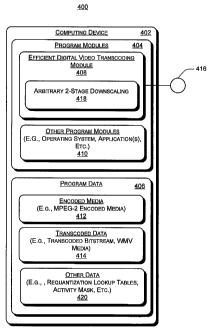
[0033] In this implementation, system 400 includes a general-purpose
computing device 402. Computing device 402 represents any type of computing
device such as a personal computer, a laptop, a server, handheld or mobile
computing device, etc. Computing device 402 includes program modules 404 and
program data 406 to transcode an encoded bitstream in a first data format
(e.g.
MPEG-2) to a bitstream encoded into a different data formats (e.g., WMV).
Program modules 404 include, for example, efficient digital video transcoding
module 408 ("transcoding module 408") and otller program modules 410.
Transcoding module 408 transcodes encoded media 412 (e.g., MPEG-2 media)
into transcoded media 414 (e.g., WMV media). Other program modules 410
include, for exainple, an operating system and an application utilizing the
video
bitstream transcoding capabilities of transcoding module 408, etc. In one
implementation, the application is part of the operating system. In one
implementation, transcoding module 408 exposes its transcoding capabilities to
the
application via an Application Programming Interface (API) 416.
High-Speed Profile Transcoding
[0034] Fig. 5 shows an exemplary simplified integrated closed-loop
cascaded pixel-domain transcoder without error propagation. For purposes of
discussion and illustration, the components of Fig. 5 are described in
reference to
the components of Fig. 4. For instance, the architecture of Fig. 5 is
representative
of one exemplary architecture implementation of transcoding module 408 of Fig.
4.
Referring to the architecture 500 Fig. 5, as compared to the architecture in
Fig. 3,
please note that this is an integrated architecture without separate encoder
and
decoder components. Additionally, please note that the MV refining motion
CA 02621428 2008-03-05
WO 2007/033346 PCT/US2006/035939
estimation module is removed from the MC in MPEG-2 decoder. Additionally,
MC in the WMV encoder is merged to a MC that operates on accumulated
requantization errors. In this manner, the transcoding architecture of Fig. 5
significantly reduces computation complexity for high-speed transcoding of
progressive and interlaced video data formats.
[0035] Please note that the WMV transform is different from the one used in
MPEG-2. In MPEG-2, standard floating point DCT/IDCT is used whereas the
integer transform, whose energy packing property is akin to DCT, is adopted in
WMV. As a result, the IDCT in the MPEG-2 decoder and the VC1-T in WMV
encoder do not cancel out each other. The integer transform in WMV is
different
from the integer implementation of DCT/IDCT. The integer transform in WMV is
carefully designed with all the transform coefficients to be small integers.
Conventional transcoders are not integrated to transcode a bitstream encoded
with
respect to a first transform to a second transform that is not the same as the
first
transforin.
[0036] Equation 3 provides an exemplary transform matrix for 8x8 VC1-T.
12 12 12 12 12 12 12 12
16 15 9 4 -4 -9 -15 -16
16 6 -6 -16 -16 -6 6 16
T_ 15 -4 -16 -9 9 16 4 -15 (3)
$ 12 -12 -12 12 12 -12 -12 12
9 -12 4 15 -15 -4 16 -9
6 -16 16 -6 -6 16 -16 6
4 -9 15 -16 16 -15 9 -4
[0037] Equation 3 in combination with equations 4 and 5, which are
described below, indicate how two different transforms are implemented into a
scaling component of transcoding module 408 (Fig. 4). In one implementation,
the
11
CA 02621428 2008-03-05
WO 2007/033346 PCT/US2006/035939
accuracy of VC 1-T is 16-bit accuracy, which is very suitable for MMX
implementation. As a result, the codec complexity can be significantly
reduced.
[0038) Fig. 6 shows an exemplary simplified closed-loop DCT-domain
transcoder. The architecture of Fig. 6 is representative of one exemplary
architecture implementation of transcoding module 408 (Fig. 4). The
architecture
600 of Fig. 6 is a simplified architecture as compared to the architecture 500
of Fig.
5. Referring to Fig. 6, let C8 be the standard DCT transform matrix, B, the
inverse
quantized MPEG-2 DCT block, and b, the IDCT of B, then the MPEG-2 IDCT is
calculated as follows:
b = CSBC$
Let B be the VC 1-T of b, then B is calculated as:
B = T$bT$ o N88
where o denotes element-wise multiplication of two matrices, and N88 is the
normalization matrix for VC1-T transform which is calculated as follows:
,
N88 = Cs ' ~s
with
C8 =[8/288 8/289 8/292 8/298 8/288 8/289 8/292 8/298];
B is directly computed from B, using the following formula:
B = T$(C$BC$)T8 - N$$ (4)
[0039] To verify that T$C$ and C8T8 are very close to diagonal matrices, if
we apply the approximation, then Equation 4 becomes an element-wise scaling of
matrix B. That is,
B=B-Sg$ (5)
where
S$$ = diag(TgC$ )- diag(CgTB ) o N88
12
CA 02621428 2008-03-05
WO 2007/033346 PCT/US2006/035939
[0040] Equation 5 shows that the VC1-T in WMV encoder and the IDCT in
MPEG-2 decoder can be merged. Consequently, the architecture in Fig. 5 can be
further simplified to the one shown in Fig. 6. Detailed comparison reveals
that the
two DCT/IDCT modules are replaced by two VC1-T and inverse VC1-T modules.
In one implementation, a simple scaling module is also added. Two switches are
embedded along with and an activity mask in this architecture. These embedded
components, as described below, are used for dynamic control of the complexity
of
transcoding coating operations of transcoder 408 (Fig. 4). At this point,
these
components are connected. The 16-bit arithmetic property of the WMV transform
lends itself to parallel processing for PC and DSP. In view of this,
computation
complexities are significantly reduced. Moreover, since all the elements of
the
scaling matrix, S88, are substantially close in proximity with respect to one
another,
this computation, and one implementation, is replaced by a scalar
multiplication.
[0041] Figs. 5 and 6 show exemplary respective closed-loop transcoding
architectures, wherein a feedback loop is involved. In this implementation,
the
feedback loop, which includes VC-1 dequantization, VC-1 inverse transform,
residue error accumulation and MC on the accumulated error, compensates for
the
error caused by the VC-1 requantization process. Requantization error is a
main
cause of the drifting error for bit-rate-reduction transcoders, such as that
shown in
Fig. 1. Although the transcoding architectures of Figs. 5 and 6 are not
completely
drift-free, even with error compensation, the drifting error is very small.
This is
because the remaining cause of drift error is the rounding error during motion
compensation filtering. One merit of residue error compensation is that the
architectures of Figs. 5 and 6 provide for dynamically turning on or off the
compensation process, as described below with respect to TABLE 2. The
transcoding architecture of Fig. 6 performs pure bit rate reduction
transcoding
13
CA 02621428 2008-03-05
WO 2007/033346 PCT/US2006/035939
from MPEG-2 to WMV such as SD to SD or HD to HD conversion in a
substantially optimal mamier.
[0042] More particularly, conventional cascaded transcoder architectures
(e.g., the architectures of Figs. 1 and 2) lack complexity flexibility. With
respect
to computation savings, the most that such conventional architecture can
achieve is
through MV reuse and mode mapping. On the other hand, accumulated residue
error compensation architectures, for example, the architecture of Fig. 6 (and
the
architectures of Figs. 8 and 10, as described below) have built-in scalability
in
terms of complexity. TABLE 2 shows exemplary meanings of switches in Fig. 6.
TABLE 2
Exemplary Switches for Dynamic Control of Transcoding Speed and Quality
So Block Error accumulation switch
level
S i Block Error update switch
level
S2 Block Early skip block decision switch
level
[0043] After transcoding module 408 of Fig. 4 has implemented drift-free
simplification, an application can dynamically trade-off between the
complexity
and the quality to accelerate transcoding speed. In this implementation,
quality
can be traded for speed, and vice versa. In other words, some drifting error
may be
allowed in the further simplified transcoder. With this strategy, the drifting
error
introduced in the faster method is limited and fully controllable. Based on
this
consideration, three switches (So S1, and S2) are provided in the
architectures of
Figs. 6, 8, and 10: The switches are used only to the residue-error
compensation
based architectures. The switches selectively skip some time-consuming
operations to reduce complexity substantially, while introducing only a small
amount of error. The meanings of various switches are summarized in TABLE 2.
14
CA 02621428 2008-03-05
WO 2007/033346 PCT/US2006/035939
Computational decisions associated with these switches are efficiently
obtained
according to criteria described below with respect to each switch.
[0044] Switch So controls when requantization error of a block should be
accumulated into the residue-error buffer. As compared to a standard
reconstruction selector, the role of switch So is improved by adopting a fast
loolcup
table based requantization process and by providing a finer drifting control
mechanism via a triple-threshold algorithm. As a result, all observations made
with respect to switch So are considered. For example, in one implementation,
the
DCT domain Qnergy difference may be utilized as the indicator,
[0045] Switch S 1 controls when the most time-consuming module, MC of
the accumulated residue error. In one implementation, switch S 1 is on. A
binary
activity mask is created for the reference frame. Each element of the activity
mask
corresponds to the activeness of an 8x8 block, as determined by
Activity(Block;) _ 1, Energy(block) > Th
0, Energy(block, ) _< Th
where Energy(block,) is the energy of the block in the accumulated residue-
error
buffer. In one implementation, Energy(block;) is calculated spatial domain or
DCT
domain. Energy(block;) can be approximated by the sum of absolute values. If
the
MV points to blocks belonging to the area of low activity, then MC of the
accumulated residue error for that specific block is skipped.
[0046] Switch S2 performs early detection to determine whether block error
should be encoded. This is especially useful in transrating applications where
the
encoder applies a coarser quantization step size. In this implementation, if
the
input signal (the sum of the MC of accumulated residue error and the
reconstructed
residue from MPEG-2 decoder) is weaker than a threshold, then switch S2 is
turned
off so that no error will be encoded.
CA 02621428 2008-03-05
WO 2007/033346 PCT/US2006/035939
[0047] In one implementation, thresholds for the switches So, S1, and S2 are
adjusted such that earlier reference frames are processed with higher quality
and at
slower speed. This is because the purpose of the switches is to achieve a
better
trade-off between quality and speed, and because of the predictive coding
nature.
Hi ng-Quality Profile Transcoder
[0048] If bit rate change is not significant or the input source quality is
not
very high, the architecture of Fig. 6 substantially optimizes bit rate
reduction when
converting MPEG-2 bitstreams to WMV bitstreams. On the other hand, input
source may be of high quality and high quality output may be desired, also
speed
of transcoding may be a moderate requirement (e.g., real-time). A high-quality
profile transcoder, such as the cascaded pixel-domain transcoder (CDPT) of
Fig. 3
with MV refinement, meets these criteria. With this architecture, we can turn
on
all the advanced coding features of the WMV encoder to ensure higllest coding
efficiency can be achieved.
Resolution Change
[0049] In conventional media transcoding systems there are generally three
sources of errors for transcoding with spatial resolution downscaling. These
errors
are as follows:
= Downscaling: errors generated when obtaining a downscaled video. It is
typically a hardwired choice when designing operations of the downscaling
filter to make a trade-off between visual quality and complexity, especially
when downscaling in the spatial domain.
= Requantization error: As with the pure bit rate reduction transcoding
process,
this is error due to the requantization with a coarser re-quantization step
size.
16
CA 02621428 2008-03-05
WO 2007/033346 PCT/US2006/035939
= MV Error: Incorrect MV will lead to wrong motion compensated prediction.
As a result, no matter how the requantization error is compensated, and no
matter how high the bit rate goes, a perfect result is difficult to obtain if
not re-
computing the motion compensation based on the new MVs and modes. This
is a problem for conventional systems that transcode B-frames, because WMV
supports only one MV mode for B-frames. This could also be a problem if one
desires to perform optimization, which would lead to coding mode change, e.g.,
from four-MV to one-MV mode. Moreover, the problem generally exists for
chrominance components since they are typically compensated with a single
MV. (This is not a problem for the described efficient digital video
transcoding
architectures when applied to P-frames. One reason for this is because WMV
supports four-MV coding mode for P-frames).
The operations of transcoding module 408 (Fig. 4) address the last two sources
of
errors, as now described.
Requantization Error Compensation
(0050] Let D denote the down-sampling filtering. Referring to the
architecture of Fig. 3, input to the VC-1 encoder for frame (i+1) is derived
as
follows:
e,+i - DQ+i ) + D(MCmp2( $r , 1l/1Vmp2) ) - MCvc] ( br , mvvot) (6)
Assume that MCvol = MCmp2, mVmp2 = mvvc1= MVmpz/2. With the approximation
that
D(MCmp2( B, ,.MVmp2) )= MC'mp2lD(Bl),D(Wmp2) )- MC'mp2(br ,3YlVmpa) (7),
Equation 6 is simplified to the following:
,
e,+i = Y+1 + MC mp2 b; - b, , mVmp2) (8)
17
CA 02621428 2008-03-05
WO 2007/033346 PCT/US2006/035939
[0051] The first term in Equation 8, D( r+, ), refers to the downscaling
process of the decoded MPEG-2 residue signal. This first term can be
determined
using spatial domain low-pass filtering and decimation. However, use of DCT-
domain downscaling to obtain this term results in a reduction of complexity
and
better PSNR and visual quality. DCT-domain downscaling results are
substantially better than results obtained through spatial domain bi-linear
filtering
or spatial domain 7-tap filtering with coefficients (-1, 0, 9, 16, 9, 0, -
1)/32. In this
implementation, DCT-domain downscaling retains only the top-left 4x4 low-
frequency DCT coefficients. That is, applying a standard 4x4 IDCT on the DCT
coefficients retained will result in a spatially 2:1 downscaled image (i.e.,
transcoded media 414 of Fig. 4).
[0052] The second term in Equation 8, MC',,,p2( b; mV,,,p2), implies
requantization error compensation on a downscaled resolution. In this
implementation, the MC in MPEG-2 decoder and the MC in WMV encoder are
merged to a single MC process that operates on accumulated requantization
errors
at the reduced resolution.
[0053] Fig. 7 shows an exemplary merge operation of four (4) 4x4 DCT
blocks into one 8 x 8 DCT block. One practical issue remains. In DCT-domain
downscaling, four 8x8 DCT (blocks, BI through B4 in an MPEG-2 macroblock
(MB) at the original resolution) are mapped to the four 4x4 sub-blocks of an
8x8
block of the new MB at the reduced resolution and still in DCT domain (e.g.,
please see Fig. 7). In WMV, for P-frames and B-frames, the 4x4-transform type
is
allowed. As a result, nothing needs to be done further except the
abovementioned
scaling. However, for I-frames, only the 8x8-transforin type is allowed. Thus,
when dealing with I-frames, transcoding module 408 (Fig. 4) converts the four
4x4
low-frequency DCT sub-blocks into an 8x8 DCT block: B. In one implementation,
18
CA 02621428 2008-03-05
WO 2007/033346 PCT/US2006/035939
this is accomplished by inverse transforming the four 4x4 DCT sub-blocks back
into the pixel domain, and then applying a fresh 8x8 VC 1-T. In one
implementation, and to reduce computation complexity, this is achieved in the
DCT domain.
[0054] For example, let B, , BZ , B3 , and B4 represent the four 4x4 low-
frequency sub-blocks of B1, B2, B3, and B4, respectively; C4 be the 4x4
standard
IDCT transform matrix; T$ be the integer WMV transform matrix; and further let
T8 =[TL, TR] where TL and TR are 8x4 matrices. In this scenario, B is directly
calculated from B,, B2, B3, and B4 using the following equation:
II - (TLC4 ) ~I lTLC4 )' + (TLCa )Bz (7'aCa )~ + (7RCa )Bs (7iC')~ + (7RCa )B4
(~'RC4 )~
After some manipulation, B is more efficiently calculated as follows:
B = (X + Y)C' + (X - Y)D'
wherein
C = (TLC4 + TRC'4 ) 12
D=(TLC4-TRC'4)l2
X=C(B,+B3)+D(B,-B3)
Y=C(BZ+B4)+D(BZ-B4)
In one implementation, both C and D of the above equation are pre-computed.
The final results are normalized with 1V88.
[0055] Fig. 8 shows an exemplary architecture 800 for a simplified DCT-
domain numeral 2:1 resolution downscaling transcoder. In one implementation,
transcoding module 408 of Fig. 4 implements the exemplary architecture 800.
The
switches in this architecture have the same functionality as those in Fig. 6,
as
described above in reference to TABLE 2. Referring to Fig. 8, and one
implementation, the first two modules (MPEG-2 VLD and inverse quantization)
19
CA 02621428 2008-03-05
WO 2007/033346 PCT/US2006/035939
are simplified as compared to what is shown in Fig. 6. This is because
transcoding
module 408 retrieves only the top-left 4x4 portion out of the 8x8 block.
[0056] Compared to a conventional drift-low transcoder with drifting error
compensation in reduced resolution, the transcoders of Figs. 6 and 8 do not
include
a mixed block-processing module. This is because WMV supports Intra coding
mode for 8x8 blocks in an Inter coded macroblock. In other words, an Intra MB
at
the original resolution is mapped into an Intra 8x8 block of an Inter MB at
the
reduced resolution. In view of this, the MB mode mapping rule becomes very
simple, as shown immediately below:
INTRA if all mode_orig = INTRA
mode new = SKIP if all mode orig = SKIP
INTER otherwise
Existing mixed block processing operations typically require a decoding loop
to
reconstruct a full resolution picture. Therefore, the removal of mixed block
processing provides substantial computation savings as compared to
conventional
systems.
[0057] Simplified DCT-domain 2:1 resolution downscaling transcoding
architecture 800 is substantially drifting-free for P-frames. This is a result
of the
four-MV coding mode. The only cause of drifting error, as compared with a
CPDT architecture with downscaling filtering, is the rounding of MVs from
quarter resolution to half resolution (which ensures mv,,,p2 = mvvcl) and the
non-
commutative property of MC and downscaling. Any such remaining errors are
negligible due to the low-pass downscaling filtering (e.g., achieved in the
DCT
domain or in the pixel domain).
[0058] Fig. 9 shows an exemplary merge operation of four 4x4 DCT blocks
into one 8 x 8 DCT block for interlace media for 2:1 spatial resolution
CA 02621428 2008-03-05
WO 2007/033346 PCT/US2006/035939
downscaling transcoding operations, according to one embodiment. 2:1
downscaling changes resolution of an original frame by two in both horizontal
and
vertical directions. In one implementation, this interlace process is
implemented
by transcoding module 408 of Fig. 4. More particularly, for interlace coded
content, the top-left 8x4 sub-block in every MB is reconstructed by shortcut
MPEG-2 decoder, both fields are smoothed by low pass filter in vertical
direction,
then one field is dropped before the WMV encoding process.
MV Error Compensation
[0059] Although WMV supports four MV coding mode, it is typically only
intended for coding P-frames. As a result, system 400 (Fig. 4) implements the
architecture of Fig. 6 when there are no B-frames in the input MPEG-2 stream
or
the B-frames are to be discarded during the transcoder towards a lower
temporal
resolution. One reason for this is that WMV allows only one MV per MB for B-
frames. In such a scenario, transcoding module 408 (Fig. 4) composes a new
motion vector from the four MVs associated with the MBs at the original
resolution. Each of the previously mentioned MV composition methods is
compatible. In one implementation, transcoding module 408 implements median
filtering. As described, incorrect MV will lead to wrong motion compensated
prediction. To make matters worse, no matter how the requantization error is
compensated, and no matter how high the bit rate goes, perfect results are
difficult
to obtain if not re-doing the motion compensation based on the new MVs.
Therefore, we provide an architecture that allows such motion errors to be
compensated.
[0060] Again, referring to the architecture of Fig. 3, input to the VC-1
encoder for frame (i+l), which is assumed to be a B-frame, is derived as
follows:
21
CA 02621428 2008-03-05
WO 2007/033346 PCT/US2006/035939
@,+i = D( i,+, )+ D(MCmp2( Br , MVmp2) )- MCvc1(b, o mVvcl) (9);
with the approximation that
D(MCmp2( B,, MVmp2) )= MC'mp2(D( Bi ), D(MUmp2) )= MC'mp2(b, , mvmp2) ) (10)
[0061] Equation 9 is simplified to
ew - D(P,+t )+ MC'mp2(b, , mVmp2) - MC'vcl(~, , mvvol) l l 1)
In view of Equation 11, the following is obtained:
er+i = D(1) + MC~mp2(6,, fYlVmp2) - MC'vc1( b, , mvvcl)
= D(1) +[MC'mp2( b, 9 fY1Vmp2) -MC'vc1( b, ) mvvcl)l + MC'vc1( b, ' ly2vvcl) -
MC'vc1(b, , mvvcl)
= D( i;+, ) + [MC'mp2(b, ~ mVmp2) -MC'vc1( b, ~ mvvcl)]+ MC'vcl(b, - b,
,T7Zvvc1) (12)
[0062] The two terms in the square brackets in Equation 12 compensate for
the motion errors caused by inconsistent MVs (i.e., mvmp2 is different from
mvvcl)
or caused by different MC filtering methods between MPEG-2 and WMV. The
corresponding modules for this purpose are highligllted and grouped into a
light-
yellow block in Fig. 10.
[0063] Fig. 10 shows an exemplary simplified 2:1 downscaling transcoder
architecture with full drift coinpensation, according to one embodiment. In
one
implementation, transcoding module 408 of Fig. 4 iinplements the exemplary
architecture of Fig. 10. Referring to Equation 12, please note that MC'mp2( b;
,
mvmp2) is performed for all the 8x8 blocks that correspond to original Inter
MBs,
and fYiVmp2 - MUmp2l2 with quarter pixel precision. The MV used in the VC-1
encoder is a single MV: mv,c1= median(MVmp2)/2. Note that with respect to the
motion-error-compensation module, the accuracy of mvv,l can go to quarter-
pixel
level. The last term in Equation 12 compensates for the requantization error
of
reference frames. Since B-frames are not reference for other frames, they are
more
22
CA 02621428 2008-03-05
WO 2007/033346 PCT/US2006/035939
error tolerant. As a result, an application can safely turn off the error
compensation
to achieve higher speed. Again, such approximation is intended for B-frames
only.
Please note that MC for motion error compensation operates on reconstructed
pixel
buffers while the MC for requantization error compensation operates on
accumulated residue error buffer.
[0064] As to the MC, Intra-to-Inter or Inter-to-Intra conversion can be
applied. This is because the MPEG-2 decoder reconstructed the B-frame and the
reference frames. In this implementation, this conversion is done in the mixed
block-processing module in Fig. 10. Two mode composition methods are possible.
And one implementation, the dominant mode is selected as the composed mode.
For example, if the modes of the four MBs at the original resolution are two
bi-
directional prediction mode, one baclcward prediction mode and one forward
prediction mode, then bi-directional prediction mode is selected as the mode
for
the MB at the reduced resolution. In another implementation, the mode that
will
lead to the largest error is selected. In view of this example, suppose using
the
backward mode will cause largest error. In this scenario, the backward mode is
chosen such that the error can be compensated. Results show that the latter
technique offers slightly better quality as compared to the former mode
selection
technique.
[0065] An exemplary architecture according to Equation 12 is shown in Fig.
10. There are four frame-level switches specifically for this architecture, as
shown
in TABLE 3.
23
CA 02621428 2008-03-05
WO 2007/033346 PCT/US2006/035939
TABLE 3
Exemplary Frame-Level Switches
Sip Frame Switch to be closed for I- and P-frames
level only
Sp Frame Switch to be closed for P-frames only
level
SB Frame Switch to be closed for B-frames only
level (= !Sip)
Sjp/g Frame Switch to be closed for I- and P-frames
level only if there are B-frames
[0066] The four frame-level switches ensure different coding paths for
different frame types. Specifically, the architecture does not perform:
residue-
error accumulation for B-frames (SIp), does not perform MV error compensation
for I- and P-frames (SB), and does not reconstruct reference frames if there
is no B-
frames to be generated (SIpiB). Please note the frame-level switch SB can be
turned
into block-level switch since the MV error needs to be compensated only when
the
corresponding four original MVs are significantly inconsistent.
[0067] More particularly, switch Sip is closed only for I-frames or P-frames,
Switch Sp is closed only for P-frames, and switch SB is closed only for B-
frames.
The resulting architecture is not as complex as the reference cascaded pixel-
domain transcoder of Fig. 3. One reason for this is that the explicit pixel-
domain
downscaling process is avoided. Instead, pixel-domain downscaling is
implicitly
achieved in the DCT domain by siinply discarding the high DCT coefficients.
This architecture has excellent complexity scalability achieved by utilizing
various
switches, as described above with respect to TABLE 2.
[0068] For applications that demand ultra-fast transcoding speed, the
architecture of Fig. 10 can be configured into an open-loop one by turn off
all the
switches. This open-loop architecture can be further optimized by merging the
dequantization process of MPEG-2 and the requaiitization process of WIvIV. The
24
CA 02621428 2008-03-05
WO 2007/033346 PCT/US2006/035939
inverse zig-zag scan module (inside VLD) of MPEG-2 can also be combined with
the one in WMV encoder.
Chrominance Components
[0069] With respect to chrominance components in MPEG-2 and in WMV,
the MV and the coding mode of chrominance components (UV) are derived from
those of luminance component (Y). If all the four MBs at the original
resolution
that correspond to the MB at the reduced resolution have consistent coding
mode
(i.e., all Inter-coded or all Intra-coded), there is no problem. However, if
it is not
case, problems result due to different derivation rules of MPEG-2 and WMV. In
MPEG-2, the UV blocks are Inter coded wllen the MB is coded with Inter mode.
However, in WMV, the UV blocks are Inter coded only when the MB is coded
with Inter mode and there are less than three Intra-coded 8x8 Y blocks. This
issue
exists for both P-frames and B-frames. Transcoding module 408 of Fig. 4
addresses these problems as follows:
= Inter-to-Intra conversion: When the Inter-coded MB has three Intra-coded 8x8
Y blocks (it is iinpossible for an Inter-coded MB to have all four 8x8 Y
blocks
Intra coded), the UV blocks are Intra coded. In this case, one MB at the
original
resolution is Inter-coded along with corresponding UV blocks. These UV
blocks will be converted from Inter mode to Intra mode. Since the Human
Visual System (HVS) is less sensitive to the chrominance signals, transcoding
module 408 utilizes a spatial concealment technique to convert the 8x8 UV
blocks from Inter to Intra mode. In one implementation, the DC distance is
utilized as an indicator to determine the concealment direction. Concealment
is
achieved via a simple copy or any other interpolation method.
= Intra-to-Inter conversion: When an Inter-coded MB has one or two Intra-coded
8x8 Y blocks, transcoding module 408 inter-codes the UV blocks. In this
CA 02621428 2008-03-05
WO 2007/033346 PCT/US2006/035939
scenario, there are one or two Intra-coded MBs among the four corresponding
MBs at the original resolution. These UV blocks are converted from Intra mode
to Inter mode. In this iinplementation, transcoding module 408 utilizes a
temporal concealment technique called the zero-out metllod to handle these
blocks, and thereby, avoid the decoding loop.
[0070] Using error concealment operations to handle mode conversion for
chrominance component, error introduced into a current frame is negligible and
can be ignored, although it may cause color drifting in subsequent frames.
Drifting for the chrominance component is typically caused by incorrect
motion.
To address this and improve quality, in one implementation, transcoding
module 408 uses reconstruction based compensation for the chrominance
component (i.e., always applying the light-yellow module for the chrominance
component).
Rate Control
[0071] Fig. 11 shows an exemplary virtual buffer verifier buffer (VBV)
model for a decoder. A decoder based on the VBV model of Fig. 11 will
typically
verify an existing MPEG-2 bitstream. In this implementation, if the video rate
is
decreased proportional to the input rate, then the transcoded WMV bitstream
will
automatically satisfy the VBV requirements. In view of this, the efficient
digital
video transcoding architecture of this specification makes the coded frame
size
proportional to the input frame size for all the frames. These novel
architectures
continually compensate for accuinulated differences between the target frame
size
and the actual resultant frame size, and obtain, via training, a linear
quantization
step (QP) mapping rule for different bit rate ranges.
26
CA 02621428 2008-03-05
WO 2007/033346 PCT/US2006/035939
[0072] For high bit rate, there is an approximate formula between coding
bits (B) and quantization step (QP) which is also used in MPEG-2 TM-5 rate
control method.
B=S. x (13)
QP
where S is the complexity of frame, X is model parameters. Assuming the
complexity of a frame remains the same for different codecs:
~vcl /Bnq2 /Bn,p2
QPval )'l )'QPnp2 =k'l R QPõp2
X1I1112 BvCl "~VCl
where QPvc1 is the QP value used in WMV re-quantization, QPmp2 is QP value of
MPEG-2 quantization, and k is the model parameter related to the target bit
rate.
In one implementation, the following linear model is utilized:
QPvcl / QPmp2 =k'(Bmp2l Bv,,)+t (14)
The values of parameter k and t for low, medium and high bit rate cases are
listed
in TABLE 4 using the linear regression method.
TABLE 4
EXEMPLARY PARAMETER VALUES FOR LINEAR REGRESSION
METHODOLOGY
Frame Type I frame P frame B frame
Parameters k t k t k t
Low (<1Mbps) 0.612861 -0.194954 0.016081 3.128561 0.076037 2.264825
Med (<3Mbps) 0.314311 0.070494 0.041140 1.400647 0.207292 0.545977
High 0.682409 -0.248120 0.057869 1.115930 0.199024 0.441518
[0073] An exemplary detailed rate control algorithm based on Equation 14
is shown in TABLE 5, where the meanings of various symbols in the algorithm
presented in TABLE 5 are defined in following TABLE 6.
27
CA 02621428 2008-03-05
WO 2007/033346 PCT/US2006/035939
TABLE 5
EXEMPLARY RATE CONTROL ALGORITHM
Initialize SumD = 0;
While (MPEG-2 stream is not end)
{
Step 1: Decode one MPEG2 frame and get Bmp2 and QPmp2;
_
Step2: Bpred_vcl -Binp2 ~]
R,np2
Bvc1 = '8pred_vcl + SumD
If (B,,l <0) then B,c1=1;
QP,cl = (k - B p2 + t) = QPnp2 ~
vc]
Round and Clip QP,I to [1, 31];
Step3: Encode this frame into WMV frame using QPvc1;
Step4: Obtain the actual coded WMV frame size Bactual_vcl;
Update SumD: SumD = SumD + Bprea_vcl - Bactual_vcl ;
}
TABLE 6
DEFINITIONS OF SYMBOLS USED IN THE ALGORITHM OF TABLE 5
BmpZ MPEG-2 frame size;
Rinp2 MPEG-2 stream bit rate;
Rvc, Target WMV stream bit rate;
Bpred_vcl WMV frame size predicted by the ratio of
bit rate;
BVe, Expected WMV frame size to encode (new
bit rate);
Bacrnar vc] Actual encoded WMV frame size;
SumD Accumulated differences between the
predicted and actual WMV frame size from
be innin .
Arbitrarily Resolution Change
[0074] Conversion of contents from HD resolution to SD resolution, for
example to support legacy SD receivers/players, is useful. Typical resolutions
of
HD format are 1920x1080i and 1280x720p while those for SD are 720x480i,
28
CA 02621428 2008-03-05
WO 2007/033346 PCT/US2006/035939
720x480p for NTSC. The horizontal and vertical downscaling ratios from
1920x1080i to 720x480i are 8/3 and 9/4, respectively. To keep the aspect
ratio,
the final downscaling ratio is chosen to be 8/3 and the resulting picture size
is
720x404. Similarly, for 1280x720p to 720x480p, the downscaling ratio is chosen
to be 16/9 and the resulting picture size is 720x404. Black banners are
inserted to
make a full 720x480 picture by the decoder/player (instead of being padded
into
the bitstream).
[0075] According to digital signal processing theory, a substantially optimal
downscaling methodology for a downscaling ratio m/n, would be to first up
sample
the signal by n-fold (i.e., insert n-1 zeros between every original samples),
apply a
low-pass filter (e.g., a sine function with many taps), and then decimate the
resulting signal by m-fold. Perforining such operations, any spectruin
aliasing
introduced by the down-scaling would be maximally suppressed. However, this
process would also be very coinputationally expensive, and difficult to
implement
with in real-time because the input signal is high definition. To reduce this
computational complexity, a novel two-stage downscaling strategy is
implemented.
[0076] Fig. 12 shows a transcoder with arbitrarily spatial resolution
downscaling, according to one embodiment. In one implementation, transcoding
module 408 of Fig. 4 implements architecture of Fig. 12. In one
implementation,
the arbitrary downscaling transcoder is a non-integrated transcoder, such as
in Fig.
12. In another implementation, the following arbitrary downscaling transcoding
operations, which are described below with respect to Fig. 12, are implemented
in
an integrated transcoder such as that shown in Figs. 5, 6, 8, and/or 10.
[0077] Referring to Fig. 12, system 1200 implements two-stage
downscaling operations to achieve any arbitrary downscaling target. Results of
the
first stage downscaling are embedded into the decoding loop. This reduces the
29
CA 02621428 2008-03-05
WO 2007/033346 PCT/US2006/035939
complexity of the decoding operations. For example, to achieve an 8/3
downscale
ratio, downscaling operations are first implemented to downscale by 2/1. The
results of this first stage downscaling are input into the decoding loop,
wherein
second stage downscaling is performed in the spatial domain. In this example,
second stage downscaling operations downscale by 4/3 to achieve an 8/3
downscale ratio. In another example, a downscale ratio of 16/9 is achieved by
system 1200 by applying 4/3 downscaling twice (in two stages). This two-stage
downscaling methodology utilizes the previously discussed DCT-domain
downscaling strategy, and then fully embeds the first stage downscaling
results
into the decoding loop. Since resolution is significantly reduced after the
first stage
downscaling, we can continue to apply the optimal downscaling method on the
pixel-domain.
[00781 Referring to Fig. 12, please note that multiple MVs
(between [zzjx[iij
71 and[n2] x[jZ
are associated with a new MB (the MV scaling and filtering modules).
Exemplary Procedure
[0079] Fig. 13 illustrates a procedure 1300 for efficient digital video
transcoding, according to one embodiment. In one implementation, transcoding
module 408 of Fig. 4.implements the operations of procedure 1300. Referring to
Fig. 13, at block 1302, the procedure receives an encoded bitstream (e.g.,
encoded
media 412 of Fig. 4). At block 1304, the procedure partially decodes the
encoded
bitstream according to a first set of compression techniques associated with a
first
media data format (e.g., MPEG-2, MPEG-4, etc.). The partial decoding
operations
generate an intermediate data stream. The integrated transcoder does not
perform
full decoding. For example, in cases where the MC of the "conceptual" MPEG-2
CA 02621428 2008-03-05
WO 2007/033346 PCT/US2006/035939
decoder is merged with that of the WMV encoder, it is hard to describe the
decoding operations as performing MPEG-2 decoding. At block 1306, if
downscaling of the intermediate data stream is desired, the procedure
downscales
data associated with the encoded bitstream in a first stage of downscaling.
The
first stage of downscaling is implemented in the DCT domain of a decoding
loop.
At block 1308, if two-stage downscaling is desired, the procedure further
downscales in the spatial domain the data that was downscaled in the DCT
domain
(see block 1306).
[0080] At block 1310, the data decoded according to the first set of
compression techniques is encoded with a second set of compression techniques.
In one implementation, procedure 1300 is implemented within a non-integrated
transcoding architecture, such as that shown and described with respect to
Figs. 12
and 14. In this implementation,.the second set of compression, techniques is
the
same as the first set of compression techniques. In another implementation,
procedure 1300 is implemeiited within an integrated transcoding architecture,
such
as that shown and described with respect to Figs. 5-11, and 14. In this other
implementation, the second set of compression techniques is not the same as
the
first set of compression techniques. For example, in one implementation, the
first
set of compression teclhniques is associated with MPEG-2, and the second set
of
compression techniques is associated with WMV.
An Exemplary Operatina Environment
[0081] Fig. 14 illustrates an example of a suitable computing environment in
which efficient digital video transcoding may be fully or partially
implemented. Exemplary computing environment 1400 is only one example of a
suitable computing environment for the exemplary system 400 of Fig. 4, and is
not
intended to suggest any limitation as to the scope of use or functionality of
systems
31
CA 02621428 2008-03-05
WO 2007/033346 PCT/US2006/035939
and methods the described herein. Neither should computing environment 1400 be
interpreted as having any dependency or requirement relating to any one or
combination of components illustrated in computing environment 1400.
[0082] The methods and systems described herein are operational with
numerous other general purpose or special purpose computing system,
enviromnents or configurations. Examples of well-known computing systems,
environments, and/or configurations that may be suitable for use include, but
are
not limited to personal coinputers, server computers, multiprocessor systems,
microprocessor-based systems, networlc PCs, minicomputers, mainframe
computers, distributed computing environments that include any of the above
systems or devices, and so on. Compact or subset versions of the frameworlc
may
also be implemented in clients of limited resources, such as handheld
computers,
or other computing devices. The invention is practiced in a networlced
computing
environment where tasks are perforined by remote processing devices that are
linked through a communications network.
[0083] With reference to Fig. 14, an exeinplary system providing efficient
digital video transcoding architecture includes a general-purpose computing
device
in the form of a computer 1410 implementing, for example, initiator operations
associated with computing device 102 of Fig. 1. Components of computer 1410
may include, but are not limited to, processing unit(s) 1418, a system
memory 1430, and a system bus 1421 that couples various system components
including the system memory to the processing unit 1418. The system bus 1421
may be any of several types of bus structures including a memory bus or memory
controller, a peripheral bus, and a local bus using any of a variety of bus
architectures. By way of example and not limitation, such architectures may
include Industry Standard Architecture (ISA) bus, Micro Channel
32
CA 02621428 2008-03-05
WO 2007/033346 PCT/US2006/035939
Architecture (MCA) bus, Enhanced ISA (EISA) bus, Video Electronics Standards
Association (VESA) local bus, and Peripheral Component Interconnect (PCI) bus
also lcnown as Mezzanine bus.
[0084] A computer 1410 typically includes a variety of computer-readable
media. Computer-readable media can be any available media that can be accessed
by computer 1410, including both volatile and nonvolatile media, removable and
non-removable media. By way of example, and not limitation, computer-readable
media may comprise computer storage media and communication
media. Computer storage media includes volatile and nonvolatile, removable and
non-removable media implemented in any method or technology for storage of
information such as computer-readable instructions, data structures, program
modules or otller data. Computer storage media includes, but is not limited
to,
RAM, ROM, EEPROM, flash memory or other memory technology, CD-ROM,
digital versatile disks (DVD) or other optical disk storage, magnetic
cassettes,
magnetic tape, magnetic disk storage or other magnetic storage devices, or any
other medium which can be used to store the desired information and which can
be
accessed by computer 1410.
[0085] Communication media typically embodies computer-readable
instructions, data structures, program modules or other data in a modulated
data
signal such as a carrier wave or other transport mechanism, and includes any
information delivery media. The term "modulated data signal" means a signal
that
has one or more of its characteristics set or changed in such a manner as to
encode
information in the signal. By way of example and not limitation, communication
media includes wired media such as a wired network or a direct-wired
connection,
and wireless media such as acoustic, RF, infrared and other wireless
33
CA 02621428 2008-03-05
WO 2007/033346 PCT/US2006/035939
media. Combinations of the any of the above should also be included within the
scope of computer-readable media.
[0086] System memory 1430 includes computer storage media in the form
of volatile and/or nonvolatile memory such as read only memory (ROM) 1431 and
random access memory (RAM) 1432. A basic input/output system 1433 (BIOS),
containing the basic routines that help to transfer information between
elements
within computer 1410, such as during start-up, is typically stored in
ROM 1431. RAM 1432 typically contains data and/or program modules that are
immediately accessible to and/or presently being operated on by processing
unit 1418. By way of example and not limitation, Fig. 14 illustrates operating
system 1434, application programs 1435, other program modules 1436, and
program data 1437.
[0087] The computer 1410 may also include otlier removable/non-
removable, volatile/nonvolatile computer storage media. By way of example
only,
Figure 14 illustrates a hard disk drive 1441 that reads from or writes to non-
removable, nonvolatile magnetic media, a magnetic disk drive 1451 that reads
from or writes to a removable, nonvolatile magnetic disk 1452, and an optical
disk
drive 1455 that reads from or writes to a removable, nonvolatile optical disk
1456
such as a CD ROM or other optical media. Other removable/non-removable,
volatile/nonvolatile computer storage media that can be used in the exemplary
operating environment include, but are not limited to, magnetic tape
cassettes,
flash memory cards, digital versatile disks, digital video tape, solid state
RAM,
solid state ROM, and the like. The hard disk drive 1441 is typically connected
to
the system bus 1421 through a non-removable memory interface such as
interface 1440, and magnetic disk drive 1451 and optical disk drive 1455 are
34
CA 02621428 2008-03-05
WO 2007/033346 PCT/US2006/035939
typically connected to the system bus 1421 by a removable memory interface,
such
as interface 1450.
[0088] The drives and their associated computer storage media discussed
above and illustrated in Figure 14, provide storage of computer-readable
instructions, data structures, program modules and other data for the
computer 1410. In Figure 14, for example, hard disk drive 1441 is illustrated
as
storing operating system 1444, application programs 1445; other program
modules 1446, and program data 1447. Note that these components can either be
the same as or different from operating system 1434, application programs
1435,
other program modules 1436, and program data 1437. Operating system 1444,
application programs 1445, other program modules 1446, and program data 1447
are given different numbers here to illustrate that they are at least
different copies.
[0089] A user may enter commands and information into the computer 1410
through input devices such as a keyboard 1462 and pointing device 1461,
commonly referred to as a mouse, trackball or touch pad. Other input devices
(not
shown) may include a microphone, joystick, graphics pen and pad, satellite
dish,
scanner, etc. These and other input devices are often connected to the
processing
unit 1418 through a user input- interface 1460 that is coupled to the system
bus 1421, but may be connected by other interface and bus structures, such as
a
parallel port, game port or a universal serial bus (USB). In this
implementation, a
monitor 1491 or other type of user interface device is also connected to the
system
bus 1421 via an interface, for example, such as a video interface 1490.
[0090] The computer 1410 operates in a networked environment using
logical connections to one or more remote computers, such as a remote
computer 1480. In one implementation, remote computer 1480 represents
computing device 106 of a responder, as shown in Fig. 1. The remote
CA 02621428 2008-03-05
WO 2007/033346 PCT/US2006/035939
coinputer 1480 may be a personal computer, a server, a router, a network PC, a
peer device or other common networlc node, and as a function of its particular
implementation, may include many or all of the elements described above
relative
to the computer 1410, although only a memory storage device 1481 has been
illustrated in Figure 14. The logical comlections depicted in Figure 14
include a
local area networlc (LAN) 1481 and a wide area networlc (WAN) 1473, but may
also include other networks. Such networking environments are commonplace in
offices, enterprise-wide computer networks, intranets and the Internet.
[0091] When used in a LAN networking environment, the computer 1410 is
connected to the LAN 1471 through a network interface or adapter 1470. When
used in a WAN networlcing environment, the computer 1410 typically includes a
modem 1472 or other means for establishing communications over the WAN 1473,
such as the Internet. The modem 1472, which may be internal or external, may
be
connected to the system bus 1421 via the user input interface 1460, or other
appropriate mechanism. In a networked environment, program modules depicted
relative to the computer 1410, or portions thereof, may be stored in the
remote
memory storage device. By way of example and not limitation, Figure 14
illustrates remote application programs 1485 as residing on memory
device 1481. The networlc connections shown are exemplary and other means of
establishing a communications link between the computers may be used.
Conclusion
[0092] Although the above sections describe arbitrary resolution change
downsizing decoders in language specific to structural features and/or
methodological operations or actions, the implementations defined in the
appended
claims are not necessarily limited to the specific features or actions
described. Rather, the specific features and operations of the arbitrary
resolution
36
CA 02621428 2008-03-05
WO 2007/033346 PCT/US2006/035939
change downsizing decoder are disclosed as exemplary forms of implementing the
claimed subject matter.
For example, in one implementation, the described fast and high quality
transcoding systems and' methodologies, including transcoding, arbitrary sized
downscaling, and rate reduction are used for MPEG-2 to MPEG-4 transcoding and
MPEG-4 to WMV transcoding. For instance, the simplified closed-loop DCT-
domain transcoder in Fig. 6 can be used to transcode MPEG-4 to WMV. One
difference between MPEG-2 (IS-13818 Part.2) is that MPEG-2 only utilizes half
pixel element (pel) MV precison and bilinear interpolation in MC; there is
such a
same mode (half pel bilinear) in WMV. However, MPEG-4 supports both half pel
and quarter pel MV precision, as well as interpolation for quarter pel
positions
(different from that in WMV). To address this difference, when 1/2 pel MV is
used by MPEG-4 video, then the transcoding process is the same as MPEG-2 to
WMV transcoding, as described above. Additionally, when 1/4 pel MV is
contained in MPEG-4 video, then error is introduced due to different
interpolation
methods in MC as described above with respect to Fig. 6. Additionally, the
simplified 2:1 downscaling transcoder with full drift compensation described
above with respect to Fig. 10 is applicable to MPEG-4 to WMV 2:1 downsized
transcoding independent of change. Moreover, high quality transcoding,
including
the above described rate reduction and arbitrarily downscaling transcoding
operations of Fig. 12 are effective for MPEG-4 to WMV transcoding.
37