Note: Descriptions are shown in the official language in which they were submitted.
CA 02621602 2008-03-07
WO 2007/041590 PCT/US2006/038645
TECHNICAL FIELD
[0001] The present invention relates to a meat fabrication system and method.
More particulariy, the present invention relates to systems and methods for
separating chine bones and other material from consumable meat cuts.
BACKGROUND
[0002] In conventional meat processing operations, cuts of meat removed
from the rib and loin of a slaughtered animal, including beef, pork and lamb,
may be fabricated into various bone-in and boneless meat products. An
important step in this fabrication process is the separation of the animals'
vertebral column (or "chine") from these cuts of meat. This separation step
(commonly referred to as "chining") is performed to enable workers to
subsequently remove dorsal spinous processes, transverse processes, and
ribs to provide meat products.
[0003] Figs. I a and 1 b illustrate perspective views of two meat cuts 10 that
include chine bones 12, rib bones 14, a spinal groove 16, and a meat product
18. In Fig. 1 a, the meat product 18 is a rib cut of beef. In Fig. 1 b, the
meat
product 18 is a loin cut of beef. Lines 20 and 21 indicate exemplary cut lines
along which the chine-bones 1-2 can be-separated from the meat product 18.
The exact position of the cut line can vary depending on the source animal
(e.g., bovine, porcine, poultry, etc.), the size and shape of the meat cut 10,
and the desired meat product 18. For certain bone-in meat cuts for example,
it may be desirable to establish a cut line that intersects the spinal groove
16,
such as shown with line 21.
[0004] Traditionally, the chine bones 12 have been separated from the meat
product 18 using a manually operated band-saw or similar device.
Accordingly, the chining process is difficult, time consuming, labor intensive
and potentially presents worker safety challenges. Moreover, the chining
process is highly variable due to variations in the type, size, shape and
anatomy of the meat cuts (referred to herein as meat cut "characteristics").
These variations present a challenge to preparing consistent meat cuts with
the lowest possible yield loss.
1
CA 02621602 2008-03-07
WO 2007/041590 PCT/US2006/038645
EQQ'_Q%AWpdrBih%fg~ 166ie is a need for systems and methods of separating
chine bones from meat cuts that overcome one or more of the challenges
described above.
SUMMARY OF THE INVENTION
[0006] The present invention provides meat fabrication systems and methods.
In one embodiment, the system includes a conveyor adapted to receive a
plurality of meat cuts that include chine bones, and to advance the meat cuts
along a surface of the conveyor. The system further includes a cutting
assembly positioned with respect to the surface to define a cutting path that
intersects the surface at an angle of less than 90 degrees, and at least one
guide positioned to orientate the meat cuts relative to the cutting path such
that at least a portion of the chine bones are separated from the remaining
portions of the meat cuts as the meat cuts advance through the cutting path
that intersects the surface of the conveyor.
[0007] In one embodiment, the cutting assembly includes a saw having a saw
blade that extends through an opening in the surface to define the cutting
path. In another embodiment, the cutting path intersects the surface. In a
further embodiment, the angle and/or position of the cutting path is
adjustable
relative to the surface of the conveyor.
[0008] In certain embodiments; -the system may further include a coritrol
system adapted to regulate the operation of one or more aspects of the
system. For example, the control system can include a power source
connected to the cutting assembly, an imaging assembly for obtaining
characteristics of the meat cuts, and a processor for determining a cutting
path based on the characteristics and for communicating with the power
source to adjust the position or angle of the cutting path based on the
characteristics of the meat cuts.
[0009] In a further embodiment, the present invention provides a method for
separating chine bones from a meat cut. The method includes the steps of
positioning the meat cut on a conveyor that includes an elongate surface,
conveying the meat cut along the elongate surface towards a meat cutting
assembly that defines a cutting path, orientating the meat cut relative to the
2
CA 02621602 2008-03-07
WO 2007/041590 PCT/US2006/038645
14iri'dscb %i.~rbying the meat cuts through the cutting path to separate
at least a portion of the chine bones from the meat cuts.
BRIEF DESCRIPTION OF THE DRAWINGS
[0010] Figs. 1 a-1 b illustrate two meat cuts suitable for processing
according to
embodiments of the present invention.
[0011] Fig. 2 is a side perspective view of a meat fabrication system of an
embodiment of the present invention.
[0012] Fig. 3 is a side view of the system shown in Fig. 2.
[0013] Fig. 4 is a top view of the system shown in Fig. 2.
[0014] Fig. 5 is an end view of the system shown in Fig. 2.
[0015] F'ig. 6'ts an end view of the system shown in Fig. 2.
[0016] Fig. 7 is an end view of the system shown in Fig. 2.
[0017] Fig. 8 is a perspective view of another embodiment of a meat
fabrication system of the present invention.
[0018] Fig. 9 is a schematic illustration of a control system according to an
embodiment of the present invention.
[0019] Fig. 10 is a flow chart of a method of removing chine bones from a
meat cut according to an embodiment of the present invention.
[0020] Fig. 11 is a perspective view of the system shown in Fig. 2 in use.
[0021].r=ig. -12 is_ an_end-view of the system shown in Fig. -2- irs-use. --
[0022] Fig. 13 is a side perspective view of another embodiment of a meat
fabrication system according to another embodiment of the present invention.
[0023] Fig. 14 is an end view of the system shown in Figure 13.
[0024] Fig. 15 is a side perspective view of another embodiment of a meat
fabrication system according to another embodiment of the present invention.
[0025] Fig. 16 is an end view of the system shown in Figure 15.
[0026] Fig. 17 is an end view of a chine removal system according to another
embodiment of the present invention.
DETAILED DESCRIPTION
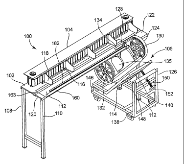
[0027] Figs. 2-7 show multiple views of a chine separation system 100
according to one embodiment of the present invention. The system 100
3
CA 02621602 2008-03-07
WO 2007/041590 PCT/US2006/038645
b6he~91Vyin6lRR'"TWbrk surface 102, a conveyor assembly 104, and a
cutting assembly 106.
[0028]The work surface 102 is a generally horizontal surface supported by
legs 108, 110, 112 and 114. The work surface 102 supports the conveyor
assembly 104, and also includes an elongate surface 112 along which meat
portions are advanced by the conveyor assembly 104. The conveyor
assembly 104 includes a conveyor belt 116 actuated by a power source (not
shown) and a plurality of panels 118 that advance meat cuts from a first end
120 to a second end 122 of the elongate surface 112.
[0029] The cutting assembiy 106 includes a saw 124 and a support assembly
126. The saw 124 includes a saw blade 128 that actuates around two wheels
130, 132 similar to a band saw. The wheels 130, 132 are positioned such that
the saw blade 128 extends through an opening 134 in the elongate surface
112. The saw assembly 124 is actuated by a power source 135 and in one
embodiment, can be operated using a control system as described below with
reference to Fig. 9.
[0030JAs shown in Figure 5, the saw blade 128 defines a cutting path 136
that intersects with the elongate surface 112 such that meat cuts that advance
along the elongate surface 112 are conveyed through the cutting path 136. In
the illustrated embodiment, the cutting path 136 is orientated at an angle
with
-respect to-the elongate surface-112-to separate-the chine bones from
remaining portions of the meat cuts. In one embodiment, the cutting path 136
has angle of less than 90 degrees relative to the elongate surface 112. In
another embodiment, the angle is between about 20 and about 65 degrees.
In a further embodiment, the angle is between about 30 and about 55
degrees. In yet a further embodiment, the angle is between about 40 and
about 55 degrees. The optimal angle may vary depending on the type and
characteristics of the meat cut. If the meat cut is a rib cut for example, the
angle of the cutting path may be between about 40 and about 45 degrees.
For loin cuts, the angle may be between about 50 and about 55 degrees.
[0031]The cutting path 136 includes an intersection point 137, which is the
point where the cutting path 136 and the elongate surface 112 intersect. In
one embodiment, the intersection point 137 is between about 2 and about 6
4
CA 02621602 2008-03-07
WO 2007/041590 PCT/US2006/038645
Wi'rfc'Hes;~fnjor'~' ~a"rticillatly, between about 2.5 to about 5 inches, from
an edge
139 of the conveyor area. The distance from the intersection point 137 to the
edge 139 may also vary depending on the type, size and other characteristics
of the meat cut being processed.
[0032]Although the illustrated embodiments utilize a band saw as part of the
cutting assembly 106, a variety of saws including table saws and circular
saws could be utilized. Furthermore, in embodiments of the present
invention, cutting assemblies that use laser or water cutting technology could
be utilized to define the cutting path 136. Water cutting assemblies used in
the food fabrication industry are commercially available from FMC
Technologies, Inc (Houston, TX).
[0033] The support assembly 126 includes a base 138 and a saw support
140. The base 138 is siidably secured to rails 142 (see Fig. 7) to provide for
lateral movement of the base 138 for reasons discussed in greater detail
below. The saw support 140 is secured to the base 138 by linking
mechanisms 146, 148. The linking mechanism 146 acts as a pivot point
between the saw support 140 and the base 138. The linking mechanism 148
includes a shaft 150 and handle 152 that allows the saw support 138 to move
relative to the base 134 for reasons discussed beiow. The saw 124 is
secured to and supported by the saw support 140.
-----_-_-----.
-[003~4]As further-shown-in-Figs.--6 and-7 the support asserribly 126described
above provides the saw 124 with two degrees of freedom with respect to the
elongate surface 112. As shown in Fig. 6, the angle of the saw blade 128 can
be adjusted by rotating a handle 152 to elevate or descend the saw support
140. In one embodiment, the angle of the saw blade 128 and its cutting path
136 can be varied from about 20 degrees to about 65 degrees relative to the
elongate surface 112. Although the illustrated embodiment shows a manual
adjustment feature, a power actuated adjustment feature known in the art
could also be used.
[0035] As further shown in Fig. 7, the base 138 can be moved laterally along
rails 142 in order to move the saw blade 128 in a direction transverse to the
longitudinal axis of the elongate surface 112. In one embodiment, for
example, the intersection point 137 can be moved from between about 2
CA 02621602 2008-03-07
WO 2007/041590 PCT/US2006/038645
from the edge 139 of the elongate surface 112. This
lateral movement of the support assembly 126 may be manual or automated
using any one of a variety of known techniques. Fig. 9 illustrates a control
system for providing such lateral movement according to one embodiment of
the present invention.
[00361 By providing at least two degrees of freedom with respect to the saw
124, the cutting path 136 through which the meat cuts are conveyed can be
adjusted based on the characteristics of particular meat cuts and/or other
desired cutting parameters. As further described below with reference to Fig.
9, some or a(i of these adjustments can be automated using a control system.
10037] Returning to Figs. 2-7, the system 100 further includes one or more
guides for orientating meat cuts relative to the cutting path 136 in order to
separate the chine bones from remaining portions of the meat cuts. Although
the number and type of guides can vary depending on the particular
embodiment, the guides iltustrated in Figs. 2-7 include a flange 160 extending
along the edge 139 of the elongate surface 112, and a ridge 162 and an
adjacent groove 163 that each extend along at least a portion of the elongate
surface 112, generaiSy paraliel to a longitudinal axis of the elongate surface
112. As described in detail with reference to Figs 10-12, the flange 160,
ridge
162, groove 163 and other guides described with reference to alternate
embodiments_play_ an _important role in-properly-orientating meat cuts
relafive
to the cutting path 136 in order to separate the chine bones.
[0038] Fig. 8 shows another embodiment of the present invention that
includes the features of the system shown in Figs. 2-7 and further includes an
imaging assembly 164 secured to the work surface 102. The imaging
assembly 164 obtains data relating to the characteristics of a meat cut, and
communicates with a control system (see Fig. 9) to adjust the operation of the
system 100 according{y=
[0039] For example, measurement of the meat cut characteristics may be
accomplished via objective criteria using the imaging assembly 164 to
determine color, surface area, linear measures such as length, width, and/or
depth, etc., and volurne measurements. Suitable imaging assemblies can
incorporate X-ray, infrared, camera, video, machine vision, ultrasound, MRI,
6
CA 02621602 2008-03-07
WO 2007/041590 PCT/US2006/038645
'4AWhibdin'~4ffieR"otraphic imaging, computerized tomography (CT) and
other known imaging modalities to determine meat cut characteristics.
[0040]As previously noted, embodiments of the present invention can utilize a
control system to automate certain operations. Figure 9 is a schematic
illustration of one example of a suitable control system 170, which includes a
processor 172, a user interface 174, the imaging assembly 164 shown in Fig.
8 and a power source 176. In use, the imaging assembly 164 obtains data
relating to characteristics of meat cuts located on the elongate surface 112
and communicates the data to the processor 172. The processor 172
analyzes the data, determines a desired cutting path 136 and communicates
with the power source 176 to actuate the saw assembly 106 to adjust the
position and/or angle of the saw blade 128 to establish the desired cutting
path 136.
[0041] To analyze the data received from the imaging assembly 164, the
processor 172 includes software that utilizes an algorithm for determining the
appropriate movement of the cutting path 136. Although the software and
algorithm will vary depending on the imaging modality, many algorithms
incorporate data relating to image pixels to determine bone dimensions, meat
thickness and the like.
[0042] In certain embodiments, the control system 170 can be operated to
-
_ start and-stop the system-100; to-change the speed of the convey6r -104_
and/or the saw biade 124. The user interface 164 allows users of the system
100 to observe the activities of the control system 170 and/or to manually
operate one or more of the operations described above. In one embodiment,
however, the system 100 is capable of operating with minimal or no worker
input.
[0043] Figs. 10-12 describe and illustrate a methods of separating chine
bones from a meat cut according to one embodiment of the present invention.
Figure 10 is a flow-chart of the method 200, which generally includes the
steps of the positioning a meat cut 10 on the elongate surface 112 (block
204), advancing the meat cut 10 towards the cutting path 136 (block 206),
optionally adjusting the position or angle of the cutting path 136 relative to
the
elongate surface 112 (block 208), orientating the meat cut 10 relative to the
7
CA 02621602 2008-03-07
WO 2007/041590 PCT/US2006/038645
guides (block 210), and then advancing the meat
cut 10 through the cutting path 136 to separate the chine bones 12 from the
meat cut 202 (block 212).
[0044] Figs. 11 and 12 show respective side and end views of the system 100
in use, in which meat cuts 10 are disposed on the elongate surface 112.
Suitable meat cuts 10 are shown and described with reference to Figs. 1 a and
1 b.
[0045] The meat cuts 10 are initially positioned near the first end 120 the
elongate surface 112 as shown in Fig. 9 such that the spinal groove 16 is
aligned with the ridge 162, the meat cut 18 is aligned with the groove 163,
and
the chine bones 12 and surrounding tissue are immediately adjacent (and
may contact) flange 160. The meat cuts 10 can be positioned in this manner
manually or via a conveyor system that transports the meat cut 10 from a prior
processing step.
[0046] When the conveyor assembly 104 is in operation, the belt 116 urges
the panel 118 into contact with the meat cuts 10 such that the meat cuts 10
are advanced along the elongate surface 112 towards the cutting path 136.
The flange 160, ridge 162 and groove 163 orientate the meat cuts 10 that
approach the cutting path 136, and may continue to guide the meat cuts 10
through the cutting path 136 while the chine bones 12 are separated.
-[0047] If-the-optional-imaging-assembly 164 is-utilized; data relating to the
characteristics of the meat cut 10 are obtained and communicated to the
processor 172 as the meat cut approaches. The processor 172 then
communicates with the power source 176 to adjust the position of the cutting
path 136, as described above, prior to the meat cut 10 reaching the cutting
path 136.
[0048] The meat portion 10 is then advanced up to and through cutting path
136, with the flange 160, ridge 162 and groove 163 orientating the meat cut
relative to the cutting path 136 such that the chine bones 12 are removed
with minimal loss of the meat product 18. After separation of the chine bone
12, the meat product 18 can be transferred to additional processing stations,
which may include processes that produce boneless meat products. The
chine bones 12 can be discarded or further processed as desired.
8
CA 02621602 2008-03-07
WO 2007/041590 PCT/US2006/038645
11[004,91 Pg"s. -'T5Vti1nffvuV additional embodiments of the system 100 shown
and described in Figs. 2-11. The system 100 shown in Figs. 13 and 14
includes the features of the system shown in Figs. 2-7, and further includes
additional guides for orientating the meat cuts 10 relative to the cutting
path
136. In particular, the system 100 includes rails 250, 252 on opposing sides
of the elongate surface 112, and generally adjacent to the cutting path 136.
The rail 250 is positioned to contact and orientate the chine bones 12 of the
meat cut 10, while the rail 252 is positioned to contact and orientate the
meat
product 18 that is to be separated from the chine bones 12.
[0050] The rails 250, 252 in the illustrated embodiment are spring loaded to
receive and/or apply a force to meat cuts 10 having varying characteristics,
and are generally shaped and positioned to further orientate the meat cut 10
just prior to and/or during cutting. It is further evident that the rails 250,
252
have arcuate surfaces that further orientate the meet cut 10 through the
cutting path 136. These arcuate surfaces may have multiple bends or curves
to optimize orientation of the meat cuts.
[0051]Although not shown in this embodiment, additional rails such as an
overhead rail could be inciuded to further optimize the orientation of the
meat
relative to the cutting path 136. Additionally, although rails 250, 252 are
illustrated as being spring-loaded, pneumatic or hydraulic cylinders could be
incorporated-to_apply a-forceto the meat cut 10. These-cylinders could be
used to positively adjust the position of the rails 250, 252 based on
characteristics of the meat cut 10, as opposed to adjusting only when
contacted by a meat cut 10. Alternatively, the rails 250, 252 could be fixed
in
a single position.
[0052] Figs. 15 and 16 illustrate another embodiment of the present invention,
which includes an arm 260, that contacts the meat portion 10 during
separation of the chine bones 12. As illustrated, the arm 260 is spring-
loaded,
and is designed to contact and orientate the meat cut 18 from the chine bones
12. As with rails 250, 252, the arm 260 could incorporate a piston and/or
cylinder to apply a force to the meat cut and/or adjust automatically based on
the characteristics of the meat cut.
9
CA 02621602 2008-03-07
WO 2007/041590 PCT/US2006/038645
't006J]PiJ. 11"Ifid9fi-~'~t6s another embodiment of the present invention, in
which the cutting assembly 106 includes a second saw 270 adjacent to the
saw 124. The saw 270 includes wheels 272, 274 and a saw blade 276. The
blade 276 is orientated to provide a cutting path 278 that is vertical or
nearly
vertical relative to the elongate surface 112. In one embodiment for example,
the cutting path 278 of blade 276 is at an angle of between about 75 degrees
and about 90 degrees relative to the elongate surface 112.
[0054] The saw 270 can be secured to same support assembly 126 as the
saw 124, and the position of the cutting path 278 can adjusted in cooperation
with the cutting path 136. Alternatively, the saw 270 could utilize a separate
support assembly that provides independent movement from the saw 124.
[0055] The addition of the saw 270 and/or additional saws further optimizes
the cutting process, and is specifically designed to reduce the amount of
waste produced when separating the chine bones from beef meat cuts such
as the meat cuts shown in Fig. 1 b.
j0056]While different embodiments of the invention have been described
herein, it is evident that various modifications, alternatives and
combinations
to the described features embodiments could be utilized in light of the
overali
teachings of the disclosure. For example, any one of the various guides used
to orientate the meat portions could be combined together, or certain guides
- --- -- -- -
_
-cou e e iminate- '-s-o long as tlie rrieaf-portion are properly brientated by
the
remaining guide or guides relative to the position of the cutting path or
paths.
10057] Similarly, depending on the number and types of guides that are
employed, it may not be necessary for the saw assembly to provide for lateral
or rotation movement. More specifically, it may be possible for the guides to
sufficiently orientate the meat to eliminate the need to modify the cutting
path
in the lateral and/or rotational direction.
[0058] Moreover, the desired alignment of the meat cut wif( vary depending on
the meat cut characteristics as well as the desired meat product. The cut
lines shown in the Figs., for example, are positioned to separate all (or a
substantial portion) of the chine bones in order to prepare boneless meat
products. ff bone-in meat cuts are desired, however, the cut line may be
positioned to leave a portion of the chine bones with the meat product. The
CA 02621602 2008-03-07
WO 2007/041590 PCT/US2006/038645
multiple cut lines by orientating the meat cut
relative to a generally fixed cutting path, by moving the cutting path
relative to
the orientation of the meat cut, or by both orientating the meat cut and
moving
the cutting path.
[0059] Accordingly, the particular arrangements are illustrative only and are
not limiting as to the scope of the invention which is to be given the full
breadth of any and all equivalents thereof.
11