Note: Descriptions are shown in the official language in which they were submitted.
CA 02621690 2008-02-19
= -1-
TITLE: STORAGE KIT
FIELD
[0001] This specification relates to furniture, for example shelving or
storage
systems.
BACKGROUND
[0002] The following is not an admission that anything described below is
citable
as prior art or part of the common general knowledge of persons skilled in the
art.
[0003] A storage system is a set of parts used to add article-supporting
elements
to a room. Article supporting elements may include, for example, shelves,
brackets or
hooks.
SUMMARY
[0004] The following summary is intended to introduce the reader to this
specification. This summary is not intended to define or limit any invention.
One or more
inventions may reside in any combination of one or more apparatus elements or
process steps selected from a set of all elements or steps described anywhere
in this
document.
[0005] This specification describes a storage system or kit for a storage
system.
The kit or storage system has components making up two or more variable height
poles
to be installed generally vertically on a lower surface, for example a floor.
The tops of
poles are attached to a common horizontal beam intended to abut an upper
surface, for
example a ceiling. Optionally, the poles may be made of multiple segments
connected
by a plastic insert with a hollow metal core. The poles may have openings, for
example
CA 02621690 2008-02-19
-2-
slots, along their lengths to accept other elements. The kit may further have
one or
more of the article-supporting elements described below.
[0006] A shelf or tool bracket has vertical and horizontal surfaces. The
vertical
surface has hooks to engage openings on a pole. The horizontal surface has
openings
to admit tools to be stored on the bracket, or fasteners to attach the end of
a shelf to the
bracket.
[0007] A slat wall bracket has hooks to engage openings on a pole on one side
and upper and lower channels to engage a vertical board on another side. The
vertical
board may be a section of a slatwall.
[0008] A poie adapter has hooks to engage openings on a pole on one side, and
openings as in the pole on another side. A shelf bracket may be attached to
the pole
and another shelf bracket may be attached to the pole adapter. Shelves at the
same
elevation may extend outwardly in both directions form the two shelf brackets.
[0009] A shelf bracket has an end with hooks to engage openings in a pole and
an upper surface. The upper surface may have a series of spaced holes. A shelf
slat
has a notch at each end to admit the upper surface of the bracket. The ends of
the
shelf slat may also have holes for a fastener to attach the shelf slat to the
upper surface
of the bracket. The holes in the upper surface of the shelf bracket may be
spaced,
relative to the width of the shelf slats, to accommodate multiple nearly
adjacent slats
forming a nearly continuous planar surface.
BRIEF DESCRIPTION OF THE DRAWINGS
[0010] Figure 1 is a schematic isometric representation of the components of a
storage system or kit.
[0011] Figure 2 is a schematic isometric representation of an assembled
storage
system made from the components in Figure 1.
CA 02621690 2008-02-19
-3-
[0012] Figures 3, 4, 5 and 6 are schematic plan view representations of steps
in
the assembly of poles of the system of Figure 2.
[0013] Figures 7, 8, 9 and 10 are schematic representations of steps in the
installation of poles and a beam of the system of Figure 2.
[0014] Figure 11 is a schematic isometric representation of a shelf slat being
installed to a shelf bracket.
[0015] Figure 12 is a schematic isometric representation of a pole bracket
adaptor of the system or kit of Figure 1.
[0016] Figure 13 is a schematic elevation view representation of a pole
bracket of
Figure,12 supporting a shelf.
[0017] Figure 14 is an enlargement of the circled area of Figure 13.
[0018] Figures 15, 16, 17 and 18 are an isometric front view, an isometric
back
view, a side view and an isometric front in use view of element H of Figure 1.
[0019] Figures 19, 20 and 21 are front, side and top views respectively of
element I of Figure 1.
[0020] Figures 22 and 23 and a top view and a cut-away partial side view of
element D of Figure 1.
[0021] Figure 24 is an isometric view of Element I of Figure 1.
[0022] Figure 25 is an isometric view of the bottom of element C or Figure 1
being assembled over the top of element D of Figure 1.
[0023] Figure 26 is an isometric view of an assemble of elements D, P, E and F
of Figure 1.
DETAILED DESCRIPTION
CA 02621690 2008-02-19
-4-
[0024] Figure 1 shows the components, or sub-assemblies of components, of a
storage system packaged as a kit. The letter to the left of each component or
sub-
assembly is a reference letter for that component or sub-assembly. The number
to the
right of each component or sub-assembly is the number of that component or sub-
assembly included in the kit. Beam A is a metal C-channel shaped beam with
slots in
its flanges and holes in its web. Pole upper section B is a hollow square post
with long
(about 9 cm) slots on all for of its sides, holes on two sides at one end, and
an interior
plate welded across its cross section about 5 cm in from the other end. Pole
middle
section C is a hollow square tube with openings in the form of short (about 2
cm) slots
60 on all four sides and an inside width that accepts the outside width of
pole upper
section B. Pole lower section D (also shown Figures 22, 23, 25 and 26) is a
hollow
square tube section like pole middle section C but with a pole section
connector 50
inserted in one end and a plate with a threaded hole welded across its other
end. The
pole section connector 50 is a section of square metal tubing 52, for example
about 20
cm long, covered on its sides with a dense plastic 54 sized and shaped to fit
snugly
inside and against the inside surfaces of pole sections C, D. Plastic covering
54 has a
flange 58 with a slot 56 to receive the ends of pole sections C, D. Shelf slat
E is a metal
C-channel shaped beam with a notch in each flange at each end and a hole
through the
web at each end in about the centre of the notches. Shelf G is a rectangular
piece of
coated particle board. Shelf bracket F (also shown in Figure 26) is a metal
plate bent to
form an upper surface with a width that fits into the slots at the end of a
shelf slat E, and
two sides. The ends of the sides are cut to provide hooks 36 adapted to engage
the
slots 60 of pole sections C, D. The sides are grooved to increase their
strength. The
upper surface has a series of spaced holes 62 adapted to allow connection to a
fastener
such as cotter pin T or a screw 64 inserted through a hole at the end of a
shelf slat E.
The holes in the upper surface are spaced so that a plurality of shelf slats E
supported
on the shelf bracket F form a nearly continuous planar surface. Slat wall
bracket H
(shown in more detail in Figures 15-18) has a piece of metal plate 10 bent at
both ends
to form a c-section with a long web 12 and cupped flanges 14. The web 12 has
holes
CA 02621690 2008-02-19
-5-
16 to admit fasteners and hooks 18 adapted to fit into the slots 60 of pole
sections C, D.
A rod 20 welded to the back of the plate has a diameter greater than the depth
of the
hooks 18 and is bent to form an upper loop 22 and two lower hooks 24. Shelf
and tool
bracket I (also shown in Figures 19-21 and 24) is a piece of metal plate 30
bent to
provide horizontal 32 and vertical 34 surfaces. The vertical surface 34 has
hooks 36 to
engage the slots of pole sections C, D. The horizontal surface 32 has holes 38
to admit
a fastener for optionally fastening to an end of a shelf, larger holes 40 to
optionally hold
tools with shafts, such as screwdrivers, and openings 42 to hold larger tools
such as
wrenches or pliers. An indented groove 44 strengthens the horizontal surface
32. Slat
wall section J (also shown in Figure 18) is a section of extruded plastic
having a cross
section that provides a groove 30 to accept the upper ends of a slat wall
attachment.
Spring K is a coil spring with an outer diameter that fits inside upper pole
section B.
Clip L is a bent piece of metal sized and shaped to fit through the slots of
middle pole
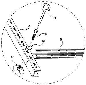
section C. Retainer M is a piece of spring steel wire bent into an open ring.
N is a bolt.
0 is a wing nut. Pole adapter P is a short section of hollow square tubing of
the same
size as pole sections C, D. Pole adapter P has hooks on one side to engage
slots in
pole sections C, D and slots as in pole sections C, D on its other three
sides. Q and R
are Allen keys. Foot S has a threaded shaft for threading into the hole in the
plate on
the bottom of lower pole section D and a foot pad. T is a cotter pin. Figure 2
shows
these components in an assembled and installed system, according to one of
multiple
options for assembling the kit or system.
[0025] Figures 3 to 6 show steps in assembling poles for the system. As shown
in Figure 3, a foot S is threaded fully, or nearly so, into the plate at the
bottom of a lower
pole section D. A middle pole section C is slipped over the connector 50 at
the other
end of lower pole section D as shown in Figure 25. Referring to Figure 4, pole
sections
C, D are positioned vertically, and upper pole section B is placed next to
them. Clip L is
inserted through the first full slots in middle pole section C below the
bottom of pole
upper section B. Retainer M is inserted through a hole in the clip L to keep
it in place.
CA 02621690 2008-02-19
-6-
Referring to Figure 4, spring K is inserted into middle pole section C to abut
the clip L.
Upper pole section B is then also inserted into the end of middle pole section
C. The
lower end of upper pole section B fits over the other end of spring K until
the end of
spring K contacts the plate inside of upper pole section B. Referring to
Figure 6, two
more poles are assembled to have the same length.
[0026] Figures 7 to 10 show steps in installing the poles and an upper beam.
Beam sections A are laid on a floor nested together at their ends to provide a
desired
length. The ends of pole upper sections B are bolted to beam sections A at a
spacing
appropriate for shelves G or shelf slats E. The assembly is lifted and
installed in rough
position between a floor and ceiling. The springs K will be partially
compressed with the
assembly in this position and hold the assembly in place while each pole B, C,
D is
moved towards a vertical position. Once the poles B, C, D are in their desired
location,
feet S are rotated to screw them out of the bottoms of lower pole sections D
to further
compress springs K. If desired, feet S can be rotated until the bottom of
upper pole
sections B abut clips L, or rotated even further to increase the compression
between the
pole B, C, D, floor and ceiling. Optionally, beam section A may be screwed to
the
ceiling, or to structure such as a joist located above the ceiling between the
ends of
poles B, C, D. This step may be unnecessary since connecting all three poles
B, C, D
together through beam sections A makes each difficult to knock over.
[0027] Figure 11 shows how a shelf slat E is fitted over a shelf bracket F and
held
in place by a cotter pin T. If desired, other shelf slats E may be fitted into
the adjacent
holes in shelf bracket F. If a shelf slat E is attached to each hole in shelf
bracket F, a
nearly continuous planar surface is created but with gaps between the slats E
of up to
about 2 or 3 cm. Figure 12 shows a pole adapter P in greater detail. As shown
in
Figures 13 and 14, the hooks of the pole adapter P may be inserted into the
slots of a
pole section C, D, and a shelf bracket F may be inserted into the slots of the
pole
adapter P. In this way, two shelf brackets F may be mounted at the same
elevation to
the same pole B, C, D. One shelf bracket F can support slats E extending to
one side
CA 02621690 2008-02-19
-7-
of the pole B, C, D while the other shelf bracket F supports slats E at the
same elevation
extending to the other side of the pole B, C, D as shown in Figure 26.