Note: Descriptions are shown in the official language in which they were submitted.
CA 02621723 2012-09-13
,
,
MICROWAVE ENERGY INTERACTIVE INSULATING STRUCTURE
TECHNICAL FIELD
This application discloses various microwave energy interactive
structures for heating, browning, and/or crisping a food item in a microwave
oven.
BACKGROUND
Microwave ovens have become a principle form of heating food in a
rapid and effective manner. Various attempts have been made to provide
microwave food materials, structures, and packages that produce effects
associated with foods cooked in a conventional oven. Such materials,
structures, and packages must be capable of controlling the distribution of
energy around the food item, utilizing the energy in the most efficient
manner, and ensuring that the food item and the material, structure, or
package has a pleasant and acceptable appearance.
BRIEF DESCRIPTION OF THE DRAWINGS
The description refers to the accompanying drawings, some of which
are schematic, in which like reference characters refer to like parts
throughout the several views, and in which:
1
,
, CA 02621723 2008-02-15
FIG. 1A schematically illustrates a cross-sectional view of an
microwave energy interactive structure according to various aspects of
the invention;
FIG. 1B schematically illustrates the structure of FIG. 1A after
sufficient exposure to microwave energy; and
FIG. 2 schematically illustrates a cross-sectional view of another
microwave energy interactive structure according to various aspects of
the invention.
SUMMARY
This application generally discloses various microwave energy
interactive structures or materials. The structures may be used to form
heating sheets, sleeves, disks, trays, cartons, pouches, packages, and
other constructs (collectively "constructs") that enhance the heating,
browning, and/or crisping of a food item in a microwave oven. The
various structures generally comprise a plurality of components or layers
assembled and/or joined to one another in a facing, substantially
contacting, layered configuration. Such layers may include a microwave
energy interactive element and a tie layer joining a pair of adjacent
layers. The tie layer may comprise a thermoplastic material.
Typically, the microwave energy interactive element comprises a
thin layer of microwave energy interactive material (i.e., a "susceptor")
(generally less than about 100 angstroms in thickness, for example, from
about 60 to about 100 angstroms in thickness) that tends to absorb at
least a portion of impinging microwave energy and convert it to thermal
energy (i.e., heat) at the interface with a food item. Susceptors often are
used to promote browning and/or crisping of the surface of a food item.
The susceptor may be supported on a microwave energy transparent
2
- ,
CA 02621723 2008-02-15
,
substrate, for example, a layer of paper or polymer film for ease of
handling and/or to prevent contact between the microwave energy
interactive material and the food item.
Upon sufficient exposure to microwave energy, the structure
transforms from a substantially flattened, planar structure to a multi-
dimensional structure having an irregular surface. In this transformed
state, the structure is capable of providing some degree of thermal
insulation between the food item and the microwave heating
environment and, therefore, may be referred to as a "microwave energy
interactive insulating structure", "microwave energy interactive insulating
material", "insulating material", or "insulating structure".
In one particular aspect, the microwave energy interactive
insulating structure comprises a layer of microwave energy interactive
material supported on a first polymer film, a support layer joined to the
layer of microwave energy interactive material, a second polymer film in
a superposed relationship with the support layer such that the support
layer is disposed between the layer of microwave energy interactive
material and the second polymer film, and a tie layer joining the support
layer to the second polymer film layer. The tie layer comprises a
thermoplastic material. Upon sufficient exposure to microwave energy,
the support layer and the second polymer film at least partially separate
from one another to define at least one insulating void between the
support layer and the second polymer film, for example, in the tie layer.
The tie layer may be formed in numerous ways and may have
various configurations and/or compositions. In one example, tie layer is
substantially continuous. In another example, the tie layer includes at
least one area having a first bond strength and at least one area having a
second bond strength greater than the first bond strength. In still another
3
, CA 02621723 2008-02-15
. .
example, the tie layer comprises at least one material that does not soften
at the softening temperature of the thermoplastic material. Such material
may be thermoplastic and have a higher softening point or may be
thermosetting, such that it has no softening point. In still another example,
the thermoplastic material has an affinity for each of the support layer
and the second polymer film, and the tie layer comprises at least one
other material that has an affinity for at least one of the support layer and
the second polymer film that differs from the respective affinity of the
thermoplastic material.
In another aspect, a method of making a microwave energy
interactive insulating structure includes joining a support layer to a
susceptor film, and joining a polymer film to the support layer to define a
bonded area, where the bonded area is adapted to at least partially
weaken in response to heat. In one variation, joining the polymer film to
the support layer defines a second bonded area adapted to remain
intact in response to heat.
In one variation, joining the polymer film to the support layer
comprises extruding a tie layer material onto the support layer and
bringing the polymer film into contact with the tie layer material. If
desired, the interior surface of the polymer film may be printed before
joining the polymer film to the support layer.
In another variation, joining the polymer film to the support layer
comprises applying a tie layer material between the polymer film and the
support layer to form the bonded area of the structure, and the method
further comprises passing the structure through a patterned nip assembly
to define an area having a first bond strength and an area having a
second bond strength greater than the first bond strength.
4
CA 02621723 2012-09-13
In still another variation, joining the polymer film to the support layer
comprises forming a tie layer between the polymer film and the support
layer, where the tie layer includes a first component that softens at a first
softening temperature and a second component that does not soften at the
softening temperature of the first component.
In yet another variation, joining the polymer film to the support layer
comprises forming a tie layer between the polymer film and the support
layer, where the tie layer includes a thermoplastic material having an
affinity
for each of the support layer and the polymer film, and at least one other
material having an affinity for at least one of the support layer and the
polymer film that differs from the respective affinity of the thermoplastic
material.
According to one aspect of the present invention there is provided a
microwave energy interactive structure comprising a support layer having a
first side and a second side opposite one another; a susceptor film joined to
the first side of the support layer, the susceptor film comprising a layer of
microwave energy interactive material supported on a first polymer film,
wherein the susceptor film is joined to the first side of the support layer so
that the layer of microwave energy interactive material is positioned
between the first polymer film and the first side of the support layer; and a
second polymer film joined to the second side of the support layer, the
second polymer film being joined to the second side of the support layer by
a substantially continuous tie layer, wherein the tie layer comprises a
thermoplastic material, and a void forms within the tie layer in response to
microwave energy.
According to a further aspect of the present invention there is provided
a microwave energy interactive structure comprising a support layer having
a first side and a second side opposite one another; a susceptor film joined
to the first side of the support layer, the susceptor film comprising a layer
of
5
CA 02621723 2012-09-13
,
,
microwave energy interactive material supported on a first polymer film,
wherein the susceptor film is joined to the first side of the support layer so
that the layer of microwave energy interactive material is positioned
between the first polymer film and the first side of the support layer; and a
second polymer film joined to the second side of the support layer, the
second polymer film being joined to the second side of the support layer by
a tie layer, wherein the tie layer comprises a first polymer and a second
polymer, and wherein a void forms within the tie layer proximate to the first
polymer in response to microwave energy.
According to another aspect of the present invention there is provided
a microwave energy interactive structure comprising a support layer having
a first side and a second side opposite one another; a susceptor film joined
to the first side of the support layer, the susceptor film comprising a layer
of
microwave energy interactive material supported on a first polymer film,
wherein the susceptor film is joined to the first side of the support layer so
that the layer of microwave energy interactive material is positioned
between the first polymer film and the first side of the support layer; and a
second polymer film joined to the second side of the support layer by a
substantially continuous tie layer, the second polymer film being joined to
the second side of the support layer to define areas having a first bond
strength and areas having a second bond strength greater than the first
bond strength, wherein voids form within the tie layer proximate to the
areas having the first bond strength in response to microwave energy.
Various other aspects, features, and advantages of the present
invention will become apparent from the following description and
accompanying figures.
5a
CA 02621723 2012-09-13
DESCRIPTION
Some aspects of the present disclosure may be understood further by
referring to the figures. For simplicity, like numerals may be used to
describe like features. It will be understood that while various exemplary
embodiments are shown and described in detail herein, any of the features
may be used in any combination, and that such combinations are
contemplated by the invention.
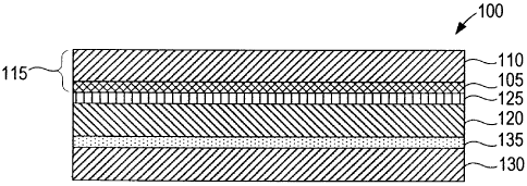
FIG. 1A depicts a schematic cross-sectional view of an exemplary
insulating structure or material 100. The insulating structure 100 includes a
layer of microwave energy interactive material 105 supported on a first
polymer film layer 110 or other substrate to collectively define a susceptor
film or simply "susceptor" 115. A support layer or simply "support" 120,
5b
. ,
CA 02621723 2008-02-15
. .
which may be a moisture-providing layer, is joined to the microwave
energy interactive material 105 using a layer of adhesive 125 or other
suitable material. A substantially continuous tie layer 135 joins the second
polymer film layer 130 to the support layer 120.
While not wishing to be bound by theory, it is believed that upon
sufficient exposure to microwave energy, the temperature of the
microwave energy interactive material 105 increases, thereby causing
water vapor to be released and/or generated by the support layer 120.
At the same time, the tie layer 135 tends to soften, thereby weakening the
bond between the second polymer film layer 130 and the support layer
120.
Depending on the degree of softening of the tie layer 135, the local
and overall bond strength of the tie layer 135, the accompanying loss of
adhesion between the second polymer film 130 and the moisture-
providing support layer 120, and various other factors, the water vapor
(and any other gases) released and/or generated by the support layer
120 may exert a pressure on the tie layer 135 and/or the second polymer
film 130, thereby creating one or more voids, cells, or bubbles (collectively
"voids") 140 between the support layer 120 and the polymer film layer 130
(e.g., in or adjacent to the tie layer 135), as shown in FIG. 1B. As a result,
the structure 100 may be transformed from a somewhat flattened
structure into an irregular, multi-dimensional structure having a somewhat
wrinkled or textured appearance. The somewhat random or
unpredictable manner in which this occurs may cause the polymer film
layer 130 to appear stretched in some areas and shrunken in others,
thereby creating a somewhat wrinkled or textured appearance.
In this wrinkled or textured, multi-dimensional configuration, the
insulating structure 100 may enhance the heating, browning, and/or
6
CA 02621723 2008-02-15
. .
crisping of a food item in a microwave oven. First, any water vapor, air,
and other gases contained in the voids 140 may provide insulation
between the food item and the ambient environment of the microwave
oven, thereby increasing the amount of sensible heat that stays within or is
transferred to the food item. Further, the wrinkling and/or deforming of
the structure 100 may cause the structure to conform more closely to the
surface of the food item, thereby placing the microwave energy
interactive material 105 into closer proximity with the food item and
enhancing the browning and/or crisping of the surface of the food item.
When exposure to microwave energy ceases, the softened tie layer
135 material cools and eventually solidifies with at least some of the
previously formed voids 140 between the support layer 120 and the
second polymer film layer 130 intact in the solidified structure. In some
instances, the voids 140 may provide a surface for safe and comfortable
handling of the heated food item and also may help to retain heat within
the package to keep the food item warm. As a result, the insulating
structures of the invention may be used to form multi-functional packages
(e.g., sleeves, pouches, wrappers, etc.) and other constructs that can be
used to store, heat, brown, crisp, transport, and contain a food item.
If desired, the structure 100 may be formed and/or processed to
selectively strengthen or weaken the bond between the support layer 120
and the second polymer film 130 to promote a desired degree of void 140
formation in the tie layer 135. Such strengthening or weakening may be
made to be inherent in the tie layer 135 or may be the result of processing
the structure 100 to mechanically or chemically strengthen or weaken
particular areas of the tie layer 135. As a result, the areas of the tie layer
135 having a greater bond strength 145 are more likely to remain intact
7
, CA 02621723 2008-02-15
, .
than areas of the tie layer 135 having a weaker bond strength 145, as
illustrated schematically in FIG. 1 B.
In one example, selected areas of the structure may be
strengthened using a patterned nip assembly or other suitable apparatus
that can be configured to create areas of no nip pressure, low nip
pressure, medium nip pressure, and high nip pressure that result in areas
having increasing degrees of bond strength. In this manner, the degree
of void formation in the tie layer can be better controlled to meet the
heating, browning, and/or crisping requirements for a particular food
item and/or heating application.
In another example, areas of greater and lesser strength can be
created by forming a tie layer with various components or materials
having differing properties. For example, the tie layer may include
materials having different softening points. As another example, the tie
layer may include materials having different affinities for the support layer
and/or second polymer layer. In such examples, voids may form in areas
of the tie layer material having a lower softening point or lesser affinity,
while voids may form at a higher temperature or later in the heating
process in areas of the tie layer having a higher softening point or affinity,
or may not form at all. Numerous other techniques for modifying the
behavior of the tie layer are contemplated by the invention.
It will be evident that any of the various techniques described
above may result in the formation of any size, shape, and configuration of
voids in the tie layer. In each of various examples, each
void
independently may have a major linear dimension of from about 0.05 to
about 0.1 in., from about 0.1 to about 0.25 in., from about 0.25 to about 3
in., for example, from about 0.25 to about 0.5 in., from about 0.5 to about
0.75 in., from about 0.75 to about 1 in., from about 1 to about 1.25 in., from
8
CA 02621723 2012-09-13
,
about 1.25 to about 1.5 in., from about 1.5 to about 1.75 in., from about
1.75 to about 2 in., from about 2 to about 2.25 in., from about 2.25 to about
2.5 in., from about 2.5 to about 2.75 in., from about 2.75 to about 3 in.,
from about 3 to about 4 in., from about 4 to about 5 in, from about 0.5 to
about 1.5 in., from about 1 to about 3 in., or any other dimension.
It is contemplated that, for some heating applications, the amount of
water vapor provided by the support layer may be insufficient to provide the
desired degree of void formation. In such applications, it may be beneficial
to include an additional source of water vapor with the structure, for
example, an additional paper or paper-based layer.
Alternatively or additionally, one or more reagents may be used to
generate a gas to promote formation of voids. Numerous examples of
reagents that may be suitable for use with the present structure are
provided in U.S. Patent Application Publication No. 2006/0289521A1,
published on Dec. 28, 2006,. In one example, the reagents may comprise
sodium bicarbonate (NaHCO3) and a suitable acid. When exposed to heat,
the reagents react to produce carbon dioxide. As another example, the
reagent may comprise a blowing agent. Examples of blowing agents that
may be suitable include, but are not limited to, p-p'-
oxybis(benzenesulphonylhydrazide), azodicarbonamide, and p-
toluenesulfonylsemicarbazide. In another example, the reagent may
comprise a hydrated mineral that releases water in response to heat.
However, numerous other reagents and released gases may be used.
By way of example, FIG. 2 schematically depicts a microwave energy
interactive insulating structure 200 including a layer of microwave energy
interactive material 205 supported on a first polymer film 210 to form a
susceptor film 215. A support layer 220 is joined to the layer of
9
CA 02621723 2008-02-15
microwave energy interactive material 205 using a layer of adhesive or
other suitable material 225. One or more reagents 230, optionally within a
carrier or coating, overlie at least a portion of the support layer 220. A
second polymer film 235 is joined releasably to the reagent layer 230 using
a substantially continuous tie layer of adhesive, polymer, or other suitable
thermoplastic material 240. After sufficient exposure to microwave
energy, water vapor or other gases are released from or generated by
the support layer 220 and the reagent layer 230. This expansion may
occur within 1 to 15 seconds in an energized microwave oven, and in
some instances, may occur within 2 to 10 seconds. The resulting gas
applies pressure on the second polymer film 235 to form a plurality of
insulating voids 245.
In another example (not shown), the support layer 220 may be
omitted. Even without a paper or paperboard layer, the water vapor or
other gas provided by the reagent may be sufficient both to form the
insulating voids and to absorb any excess heat from the microwave
energy interactive material. In still another example (not shown), the
reagent layer 203 may lie between the layer of microwave energy
interactive material 205 and the support layer 220. Numerous other
examples are encompassed hereby.
If desired, multiple layers or sheets of insulating structures may be
used to provide enhanced thermal insulation and, therefore, enhanced
browning and/or crisping. The various sheets of similar and/or dissimilar
insulating structures may be superposed in any configuration as needed
or desired for a particular application. For example, the sheets may be
arranged so that their respective susceptor film layers are facing away
from each other, towards each other, or in any other manner. The sheets
may remain separate or may be joined using any suitable process or
CA 02621723 2008-02-15
technique, for example, thermal bonding, adhesive bonding, ultrasonic
bonding or welding, mechanical fastening, or any combination thereof. If
the greatest degree of wrinkling or deforming is desirable, it might be
beneficial to use a discontinuous, patterned adhesive bond that will not
restrict the expansion and flexing of the layers within each structure. In
contrast, where structural stability is desirable, a continuous adhesive
bond between sheets might provide the desired result.
Typically, the susceptor film serves as a food-contacting side or
surface, while the polymer film adjacent to the tie layer serves as an outer
surface of a package or other construct formed. In some instances, it
may be desirable to print advertising, product information, heating
instructions, or other indicia on the outer side of a package. Thus, if
desired, the outer side or surface of the polymer film adjacent to the tie
layer may be printed with such information (generally referred to as
"printed matter"). Alternatively, the opposite side of the polymer film (i.e.,
the inner side or surface facing the support layer) may be reverse printed
prior to being joined to the support layer. This advantageously provides
optimal print clarity that cannot typically be achieved by printing directly
onto the support, particularly when the support layer is formed from paper
or any other material that commonly is prone to ink bleeding.
Any of the various layers of the structures and constructs
encompassed by the invention may be formed from various materials,
provided that the materials are substantially resistant to softening,
scorching, combusting, or degrading at typical microwave oven heating
temperatures, for example, at from about 250 F to about 425 F. The
particular materials used may include microwave energy interactive
materials, for example, those used to form susceptors and other
microwave energy interactive elements, and microwave energy
11
CA 02621723 2008-02-15
transparent or inactive materials, for example, those used to form the
polymer film layers and support layer.
The microwave energy interactive material may be an
electroconductive or semiconductive material, for example, a metal or a
metal alloy provided as a metal foil; a vacuum deposited metal or metal
alloy; or a metallic ink, an organic ink, an inorganic ink, a metallic paste,
an organic paste, an inorganic paste, or any combination thereof.
Examples of metals and metal alloys that may be suitable for use with the
present invention include, but are not limited to, aluminum, chromium,
copper, inconel alloys (nickel-chromium-molybdenum alloy with niobium),
iron, magnesium, nickel, stainless steel, tin, titanium, tungsten, and any
combination or alloy thereof.
Alternatively, the microwave energy interactive material may
comprise a metal oxide. Examples of metal oxides that may be suitable
for use with the present invention include, but are not limited to, oxides of
aluminum, iron, and tin, used in conjunction with an electrically
conductive material where needed. Another example of a metal oxide
that may be suitable for use with the present invention is indium tin oxide
(ITO). ITO can be used as a microwave energy interactive material to
provide a heating effect, a shielding effect, a browning and/or crisping
effect, or a combination thereof. For example, to form a susceptor, ITO
may be sputtered onto a clear polymer film. The sputtering process
typically occurs at a lower temperature than the evaporative deposition
process used for metal deposition. ITO has a more uniform crystal
structure and, therefore, is clear at most coating thicknesses. Additionally,
ITO can be used for either heating or field management effects. ITO also
may have fewer defects than metals, thereby making thick coatings of
12
,
% CA 02621723 2008-02-15
, .
ITO more suitable for field management than thick coatings of metals,
such as aluminum.
Alternatively, the microwave energy interactive material may
comprise a suitable electroconductive, semiconductive, or non-
conductive artificial dielectric or ferroelectric.
Artificial dielectrics
comprise conductive, subdivided material in a polymer or other suitable
matrix or binder, and may include flakes of an electroconductive metal,
for example, aluminum.
The substrate typically comprises an electrical insulator, for
example, a polymer film or other polymeric material. As used herein the
terms "polymer", "polymer film", and "polymeric material" include, but are
not limited to, homopolymers, copolymers, such as for example, block,
graft, random, and alternating copolymers, terpolymers, etc. and blends
and modifications thereof.
Furthermore, unless otherwise specifically
limited, the term "polymer" shall include all possible geometrical
configurations of the molecule. These configurations include, but are not
limited to isotactic, syndiotactic, and random symmetries.
The thickness of the film typically may be from about 35 gauge to
about 10 mil. In one aspect, the thickness of the film is from about 40 to
about 80 gauge. In another aspect, the thickness of the film is from about
45 to about 50 gauge. In still another aspect, the thickness of the film is
about 48 gauge. Examples of polymer films that may be suitable include,
but are not limited to, polyolefins, polyesters, polyamides, polyimides,
polysulfones, polyether ketones, cellophanes, or any combination thereof.
Other non-conducting substrate materials such as paper and paper
laminates, metal oxides, silicates, cellulosics, or any combination thereof,
also may be used.
13
CA 02621723 2008-02-15
In one example, the polymer film comprises polyethylene
terephthalate (PET). Polyethylene terephthalate films are used in
commercially available susceptors, for example, the QWIKWAVE Focus
susceptor and the MICRORITE susceptor, both available from Graphic
Packaging International (Marietta, Georgia). Examples of polyethylene
terephthalate films that may be suitable for use as the substrate include,
but are not limited to, MELINEX , commercially available from DuPont
Teijan Films (Hopewell, Virginia), SKYROL, commercially available from
SKC, Inc. (Covington, Georgia), BARRIALOX PET, available from bray Films
(Front Royal, VA), and QU50 High Barrier Coated PET, available from bray
Films (Front Royal, VA).
The polymer film may be selected to impart various properties to
the microwave interactive web, for example, printability, heat resistance,
or any other property. As one particular example, the polymer film may
be selected to provide a water barrier, oxygen barrier, or a combination
thereof. Such barrier film layers may be formed from a polymer film
having barrier properties or from any other barrier layer or coating as
desired. Suitable polymer films may include, but are not limited to,
ethylene vinyl alcohol, barrier nylon, polyvinylidene chloride, barrier
fluoropolymer, nylon 6, nylon 6,6, coextruded nylon 6/EVOH/nylon 6,
silicon oxide coated film, barrier polyethylene terephthalate, or any
combination thereof.
One example of a barrier film that may be suitable for use with the
present invention is CAPRAN EMBLEM 1200M nylon 6, commercially
available from Honeywell International (Pottsville, Pennsylvania). Another
example of a barrier film that may be suitable is CAPRAN OXYSHIELD OBS
monoaxially oriented coextruded nylon 6/ethylene vinyl alcohol
(EVOH)/nylon 6, also commercially available from Honeywell International.
14
CA 02621723 2008-02-15
Yet another example of a barrier film that may be suitable for use with the
present invention is DARTEK N-201 nylon 6,6, commercially available from
Enhance Packaging Technologies (Webster, New York). Additional
examples include BARRIALOX PET, available from Toray Films (Front Royal,
VA) and QU50 High Barrier Coated PET, available from bray Films (Front
Royal, VA), referred to above.
Still other barrier films include silicon oxide coated films, such as
those available from Sheldahl Films (Northfield, Minnesota). Thus, in one
example, a susceptor may have a structure including a film, for example,
polyethylene terephthalate, with a layer of silicon oxide coated onto the
film, and ITO or other material deposited over the silicon oxide. If needed
or desired, additional layers or coatings may be provided to shield the
individual layers from damage during processing.
The barrier film may have an oxygen transmission rate (OTR) as
measured using ASTM D3985 of less than about 20 cc/m2/day. In each of
various particular examples, the barrier film may have an OTR of less than
about 10 cc/m2/day, less than about 1 cc/m2/day, less than about 0.5
cc/m2/day, less than about 0.1 cc/m2/day, or any other suitable OTR or
range of OTR's.
The barrier film may have a water vapor transmission rate (WVTR) of
less than about 100 g/m2/day as measured using ASTM F1249. In each of
various particular examples, the barrier film may have a WVTR of less than
about 50 g/m2/clay, less than about 15 g/m2/day, less than about 1
g/m2/day, less than about 0.1 g/m2/day, less than about 0.05 g/m2/day,
or any other suitable WVTR or range of WVTR's.
Other non-conducting substrate materials such as metal oxides,
silicates, cellulosics, or any combination thereof, also may be used in
accordance with the present invention.
CA 02621723 2008-02-15
Likewise, the second polymer film may be any suitable polymer film
including, but not limited to, those described above. In one example, the
second polymer film layer comprises polyethylene terephthalate. The
second polymer film layer may have any suitable thickness, and in each
of various examples, the second polymer film layer may have a thickness
of from about 20 to about 70 gauge, from about 30 to about 60 gauge,
from about 40 to about 50 gauge, from about 45 to about 55 gauge, or
about 48 gauge. In one particular example, the second polymer film
layer comprises polyethylene terephthalate having a thickness of about
48 gauge.
The microwave energy interactive material may be applied to the
substrate in any suitable manner, and in some instances, the microwave
energy interactive material is printed on, extruded onto, sputtered onto,
evaporated on, or laminated to the substrate. The microwave energy
interactive material may be applied to the substrate in any pattern, and
using any technique, to achieve the desired heating effect of the food
item. For example, the microwave energy interactive material may be
provided as a continuous or discontinuous layer or coating including
circles, loops, hexagons, islands, squares, rectangles, octagons, and so
forth. Examples of various patterns and methods that may be suitable for
use with the present invention are provided in U.S. Patent Nos. 6,765,182;
6,717,121; 6,677,563; 6,552,315; 6,455,827; 6,433,322; 6,410,290; 6,251,451;
6,204,492; 6,150,646; 6,114,679; 5,800,724; 5,759,418; 5,672,407; 5,628,921;
5,519,195; 5,420,517; 5,410,135; 5,354,973; 5,340,436; 5,266,386; 5,260,537;
5221,419; 5,213,902; 5,117,078; 5,039,364; 4,963,420; 4,936,935; 4,890,439;
4,775,771; 4,865,921; and Re. 34,683. Although particular examples of
patterns of microwave energy interactive material are shown and
described herein, it should be understood that other patterns of
16
CA 02621723 2008-02-15
microwave energy interactive material are contemplated by the present
invention.
The support layer typically may comprise any suitable moisture-
containing layer. In some instances, the support layer is a dimensionally
stable layer. However, where a reagent layer is used in conjunction with
the support layer, the support layer may comprise any material, for
example, a polymer film. In one example, the support layer comprises a
paper or paper-based material generally having a basis weight of from
about 15 to about 60 lbs/ream (lb/300 sq. ft.), for example, from about 20
to about 40 lbs/ream. In one particular example, the paper has a basis
weight of about 25 lbs/ream.
The tie layer may comprise any suitable thermoplastic material that
is capable of joining, bonding, or adhering two layers together. As used
herein, the term "thermoplastic" refers to any polymeric or non-polymeric
material that is capable of becoming soft and/or pliable when heated,
without a substantial change of the inherent properties of the material. In
some examples, the tie layer may comprise a thermoplastic polymer
based on, for example, a polyolefin, a polyamide, a polyester; a
thermoplastic elastomer; any combination or copolymer of such
materials; or any other suitable material. In some particular examples, the
tie layer may comprise polypropylene, polyethylene, low density
polyethylene, or any combination or copolymer thereof.
The tie layer generally may have a softening temperature that is less
than about 425 F. In each of various examples, one or more components
of the tie layer may have a softening point of from about 75 F to about
100 F, from about 100 F to about 125 F, from about 125 F to about 150 F,
from about 150 F to about 175 F, from about 175 F to about 200 F, from
about 200 F to about 250 F, from about 250 F to about 275 F, from about
17
CA 02621723 2008-02-15
275 F to about 300 F, from about 300 F to about 325 F, from about 325 F
to about 350 F, from about 350 F to about 375 F, from about 375 F to
about 400 F, from about 400 F to about 425 F, from about 100 F to about
400 F, from about 150 F to about 350 F, from about 200 F to about 300 F,
or any other suitable range or combination of ranges of temperatures.
The tie layer may have any suitable basis weight and may be
formed in any suitable manner. In one example, the tie layer has a basis
weight or dry coat weight of from about 3 to about 18 lb/ream. In
another example, the tie layer has a dry coat weight of from about 5 to
about 15 lb/ream. In another example, the tie layer has a dry coat
weight of from about 8 to about 12 lb/ream. However, other basis
weights or dry coat weights are contemplated by the invention.
The particular process used to form the tie layer may vary
depending on the particular application. Examples of processes that may
be used include, but are not limited to, spraying, roll coating, extrusion
lamination, or any other process.
If desired, one or more pigments or opacifying agents (generally
referred to herein as "colorants") may be added to the tie layer to alter or
enhance the appearance of the resulting structure. For example, one or
more colorants may be added to the tie layer to mask the often grey
appearance of the microwave energy interactive material that may be
visible through the other side of the support layer. Examples of colorants
that may be suitable for use in this manner include titanium dioxide (Ti02),
carbon black, or any combination thereof.
The colorant may be added in any amount needed or desired for a
particular application, generally from about 1 wt % to about 15 wt % of
the tie layer. In each of various examples, the colorant may be added in
an amount of from about 1 to about 5 wt %, from about 3 to about 7 wt %,
18
CA 02621723 2008-02-15
from about 5 to about 10 wt %, from about 7 to about 12 wt %, or from
about 10 to about 15 wt %. In each of various other examples, the
colorant may be added in an amount of from about 1 to about 1.5 wt %,
from about 1.5 to about 2 wt %, from about 2 to about 2.5 wt %, from
about 2.5 to about 3 wt %, from about 3 to about 3.5 wt %, from about 3.5
to about 4 wt %, from about 4 to about 4.5 wt %, from about 4.5 to about
5 wt %, from about 5 to about 5.5 wt %, from about 5.5 to about 6 wt %,
from about 6 to about 6.5 wt %, from about 6.5 to about 7 wt %, from
about 7 to about 7.5 wt %, from about 7.5 to about 8 wt %, from about 8
to about 8.5 wt %, from about 8.5 to about 9 wt %, from about 9 to about
9.5 wt %, from about 9.5 to about 10 wt %, from about 10 to about 10.5 wt
%, from about 10.5 to about 11 wt %, from about 11 to about 11.5 wt %,
from about 11.5 to about 12 wt %, from about 12 to about 12.5 wt %, from
about 12.5 to about 13 wt %, from about 13 to about 13.5 wt %, from
about 13.5 to about 14 wt %, from about 14 to about 14.5 wt %, from
about 14.5 to about 15 wt %, or any other suitable amount.
Various aspects of the invention may be illustrated further by way of
the following examples, which are not to be construed as limiting in any
manner.
EXAMPLES 1-4
Printed 48 gauge polyethylene terephthalate (PET) film was
laminated to MICROFLEX Q susceptor material (described above) using
BR-3482 water based adhesive applied (commercially available from
Royal Adhesives, LLC) with a No. 8 Meyer rod. The laminated materials
were allowed to dry at ambient conditions for about 24 hours. After
19
CA 02621723 2008-02-15
drying, some of the samples were cut into 1" strips to evaluate the bond
quality using a Dixie adhesion tester. The results are presented in Table 1.
Table 1
Ex. Printed PET Bond strength Printing/adhesion quality
(g/in.)
1 Solid green 350-400 Poor; almost complete transfer of the
backed by ink from the PET to the MICROFLEX Q
white susceptor material
2 Blue vignette 450-500 Very good; no ink transfer from PET to
backed by the MICROFLEX Q susceptor material
white
3 Process 500-800 Good; slight ink transfer to the
pictorial MICROFLEX Q susceptor material
backed by
white
4 White only 100-125 Fair; some ink transfer to the
MICROFLEX Q susceptor material
Various samples then were evaluated for performance in a
microwave oven. Each laminate was cut into a sample about 100 mm by
100 mm in size. The corners of each sample were taped to a piece of
board stock to prevent the sample from folding over on itself in the
microwave. Each sample was heated for 10 seconds in a 1000W
microwave oven with a 700m1 competing water load. The samples were
visually judged for performance. As expected, each sample exhibited
varying degrees of delamination and insulating void formation.
EXAMPLE 5
A 48 gauge metallized PET susceptor film was coated with a
moisture-releasing reagent coating using two roll coating stations, as set
forth in Table 2. Samples were prepared at 250 feet per minute (fpm) and
200 fpm.
t CA 02621723 2008-02-15
. .
Table 2
Coating station 1 Coating
station 2
Approx. capacity (gal) 65 68
Basis 3 barrels, 300 lb 1.5 barrels,
150 lb
MgHPhosphate
MgHPhosphate
hydrate hydrate
_
Water 100 lbs (12 gal)
150 lbs (18 gal)
Airflex 460 Adhesive 335 lbs (40 gal)
355 lbs (43 gal
(Air Products)
Mg H PO4*3H20 300 lbs (2.5 100 lb
150 lbs (2 100 lb
(Jost Chemical) barrels) barrels)
Hydrad C hydrated -0- 100 lbs (2
bags
alumina filler (J.M. @50 lb)
Huber)
Michemlube 160 wax -0-
12 lbs (1.5 gal)
(Michelaman, Inc.)
The resulting material was laminated to 20 lb/ream bleached Kraft
paper using a solventless coater and a two part urethane adhesive. The
paper side of the resulting structure was then laminated to a reverse
printed 48 gauge PET film (printed with laminating inks) using a tie layer
coating of 7 lbs/ream of a blend of 85% low density polyethylene and 15%
polypropylene.
Various properties of the resulting samples were measured. The
results are presented in Table 3.
Table 3
Sample 1 Sample 2
Coating speed (fpm) 200
250
Reagent layer coat weight (113/ream) 14.7
13.1
% Moisture release in microwave oven after 6.65
7.77
3 sec
% Shrinkage in microwave oven after 3 sec 78
71
21
CA 02621723 2012-09-13
Additionally, each sample was used to heat Healthy Choice tomato
basil Panini sandwiches, raw pastry dough, and Hot Pockets pastry
sandwiches in a household microwave oven. In each example, the
experimental insulating structure achieved a greater degree of browning
and/or crisping than a plain susceptor paper.
All directional references (e.g., upper, lower, upward, downward, left,
right, leftward, rightward, top, bottom, above, below, vertical, horizontal,
clockwise, and counterclockwise) are used only for identification purposes to
aid the reader's understanding of the various embodiments of the present
invention, and do not create limitations, particularly as to the position,
orientation. Joinder references (e.g., joined, attached, coupled, connected,
and the like) are to be construed broadly and may include intermediate
members between a connection of elements and relative movement between
elements. As such, joinder references do not necessarily imply that two
elements are connected directly and in fixed relation to each other.
The scope of the claims should not be limited by the preferred
embodiments set forth in the examples, but should be given the broadest
interpretation consistent with the description as a whole.
22