Note: Descriptions are shown in the official language in which they were submitted.
CA 02622035 2008-03-10
A capacitive sound transducer having a perforated attenuation disc
The invention relates to a capacitive sound transducer comprising a diaphragm
and a counterelectrode which is disposed at a short distance from the
diaphragm
and provided with first perforations. The invention further relates to a
condenser
microphone provided with a capacitive sound transducer according to the
invention.
A capacitive sound transducer of a condenser microphone contains a planar
diaphragm which is moved by sound, and a perforated counterelectrode parallel
thereto at a short distance therefrom. The diaphragm and counterelectrode are
designed to be electrically conductive and form an electrical capacitor whose
capacitance is dependent on the diaphragm deflection caused by the sound.
Such a condenser microphone is known form DE 19715365, for example.
Due to the viscosity of the air, the narrow, air-filled space between the
diaphragm
and the counterelectrode, called the air gap, acts as a frictional resistance
which
inhibits movement of the diaphragm. This effect is used to control the
movement
of the diaphragm. However, the air gap resistance is not constant, but depends
on the momentary distance between the diaphragm and the counterelectrode.
When the diaphragm moves towards the counterelectrode, the air gap narrows,
and as a result the frictional resistance becomes greater, otherwise smaller.
For
this reason, any over-pressure in front of the diaphragm that moves the
diaphragm towards the counterelectrode will generate a smaller diaphragm
deflection than an equally large under-pressure that moves the diaphragm away
from the counterelectrode. For this reason, the movement of the diaphragm and
the change in capacitance produced as a result is not a linear copy of the
sound
signal, but is nonlinearly distorted.
The degree of nonlinearity can be reduced by decreasing the diaphragm
deflection by means of suitable measures, for example by stronger air-gap
attenuation. However, this gives rise to disadvantageous effects because the
,
CA 02622035 2008-03-10
- 2 -
transducer sensitivity is reduced, as a result of which the noise
characteristics of
the microphone are also detrimentally affected.
One advantageous option for reducing the nonlinearity of the diaphragm
deflection is provided by the "symmetrical push-pull converter", as described
in
DE 43 07 825 Al, for example. It contains a second counterelectrode with
properties identical to those of the first counterelectrode and which is
disposed in
front of the diaphragm in such a way that similar air gaps are formed on both
sides of the diaphragm. In this case, the movement of the diaphragm causes
opposite changes in resistance in the two air gaps, which mutually compensate
io each other. By this means, the movement of the diaphragm is
linearized and the
transducer distortions are minimized.
In push-pull converters, the change in capacitance between the two
counterelectrodes and the diaphragm is generally evaluated by applying the HF
principle, by connecting both counterelectrodes to the electric circuit of the
microphone. The disadvantage this involves, namely that the additional
counterelectrode disposed in front of the diaphragm is directly exposed to
humidity, with the result that its electrical insulation can be weakened, does
not
have an effect when the HF principle is applied, because said principle
results in
very low electrical impedances.
zo In the case of condenser microphones and electret microphones
operating
according to the NF principle, electrical operation of the front
counterelectrode
would then lead to substantially greater moisture sensitivity due to the very
high
electrical impedances that then arise. Until now, this disadvantage has stood
in
the way of the push-pull principle being applied to these types of microphone.
Another disadvantage of the capacitive sound transducers used in known
condenser microphones is that, in those regions lying opposite the perforated
regions of the counterelectrode, the diaphragm produces partial natural
oscillations at high frequencies, and these oscillations lead to undesired,
frequency-dependent changes in the transmission characteristics of the
=
,
CA 02622035 2008-03-10
- 3 -
condenser microphone. The frequencies at which partial oscillations occur are
dependent on the mechanical tension of the diaphragm and on the size and
shape of the counterelectrode perforations. In many cases, they are within the
frequency transmission range, that is the specified operating frequency range,
and lead to undesired frequency-dependent changes in the transmission
characteristics of the condenser microphone.
This undesired oscillation behavior at high frequencies can be sufficiently
suppressed in those regions of the diaphragm which lie opposite the non-
perforated regions of the counterelectrodes, if the distance between the
diaphragm and the counterelectrode is made so small that the viscosity of the
air
in the air gap formed by the diaphragm and the counterelectrode ensures
sufficient attenuation of diaphragm movements. However, this attenuation is
absent in those diaphragm regions which lie opposite the counterelectrode,
with
the consequence that the undesired natural oscillations of the diaphragm are
not
suppressed.
Known methods for attenuating diaphragm movements, for example by means of
a porous layer of fabric attached to the rear side of the counterelectrode,
are
unable to achieve sufficient attenuation of the partial oscillations because,
at high
frequencies, sufficiently direct action is prevented by the acoustic
resilience of the
zo air trapped in the perforated regions of the counterelectrode.
US 4,817,168 discloses a directional microphone in the form of a condenser
microphone, in which a diaphragm is arranged at a small distance from a
counterelectrode provided with perforations. Said patent also discloses an air
chamber which is separated from the counterelectrode and an intermediate wall
with openings.
A condenser microphone provided with two conventional diaphragm-
counterelectrode systems, which are separated by a solid body with a
connecting
channel, is known from GB 921,818.
,
CA 02622035 2008-03-10
- 4 -
A condenser microphone in which two perforated plates are arranged at a
distance from each other with their perforations offset from each other, and
which
are provided with an attenuation layer is known from DE 821 217.
The object of the invention consists in providing a capacitive sound
transducer
which efficaciously suppresses in a simple manner the nonlinear distortions
and
interfering partial oscillations of the diaphragm.
The object is achieved according to the invention with a capacitive sound
transducer of the kind initially specified, by a sound-permeable attenuation
disc
having second perforations, wherein the first perforations and the second
io perforations are offset in relation to each other, the
diaphragm is arranged
between the counterelectrode and the attenuation disc, and the distance
between
the attenuation disc and the diaphragm is substantially equal to the distance
between the counterelectrode and the diaphragm.
The invention is based on the realization that, when the distance between the
attenuation disc and the diaphragm is small, the undesired partial
oscillations of
the diaphragm can be efficaciously suppressed in those regions lying opposite
the perforated regions of the counterelectrode, i.e. the holes therein, by
means of
the viscosity of the air trapped between the diaphragm and the additional
attenuation disc. In order to exploit this effect, the second perforations are
offset
zo in such a way that perforated regions of the first and second
perforations do not
overlap, or only partially. The perforations of the counterelectrode and the
attenuation disc can be embodied in any way desired, not only with regard to
the
arrangement of the perforated regions, i.e. of the holes, but also with regard
to
their size, quantity and shape.
Every diaphragm essentially has modes. The frequencies of the modes at which
the diaphragm as a whole resonates are so low that the associated wavelengths
are so large in comparison to the perforation structure of the
counterelectrode
that the discontinuities in the air gap in the perforated regions produce only
a
gradual reduction of the total attenuation. At the high frequencies of the
partial
,
CA 02622035 2008-03-10
- 5 -
modes, in contrast, the ratios are fundamentally different. The regions of the
diaphragm lying opposite the perforated regions of the counterelectrode are
comparable with partial diaphragms that are mounted on the perforation edge.
The partial diaphragms can oscillate freely and relatively unattenuated in the
hole
region. All that remains is the internal attenuation of the diaphragm material
and
the influence of the surrounding air gap region, but this influence is hardly
able to
affect the perforated region via the low bending stiffness of the diaphragm.
At the lowest partial oscillation (base mode), the partial diaphragm
oscillates most
strongly in the middle, where the attenuating effect must therefore be
greatest.
to According to the invention, this is achieved by attenuating at
least the middle
region of the partial diaphragm by means of at least one air gap. In the edge
region of the partial diaphragm, the perforations of the counterelectrode and
the
attenuation disc may partially overlap without substantially impairing the
attenuation effect. As a possible guideline for sufficient attenuation, at
least half
the partial diaphragm should be covered by at least one air gap.
Additional partial oscillation modes at even higher frequencies are usually so
weak that there is no particular need to take them into consideration in this
context.
By means of the sound-permeable perforated attenuation disc according to the
invention, the other acoustic properties of the capacitive sound transducer
are
only minimally affected, whereas the natural oscillations of the diaphragm and
distortions of diaphragm movement are efficaciously suppressed, which leads to
clearly improved transmission quality of the transducer, particularly at high
frequencies. Due to the placement of the attenuation disc of the invention, a
level
of attenuation is achieved that acts locally and directly in those regions of
the
diaphragm where partial oscillations tend to occur. The local and direct
effect is
achieved by directly exploiting the viscosity of the air located between the
diaphragm and the attenuation disc for attenuation, i.e. without any
additional
mechanical or acoustic coupling elements.
,
CA 02622035 2008-03-10
- 6 -
If the distance between the diaphragm and the counterelectrode, on the one
hand, and between the diaphragm and the attenuation disc, on the other hand,
is
small enough, a sufficiently strong attenuation effect distributed as
uniformly as
possible over the diaphragm can also be achieved, even when the perforated
regions of the counterelectrode and the attenuation disc partially overlap.
This arrangement is also particularly advantageous, since the attenuation disc
ensures, whatever the diaphragm deflection, that there is a contrary change in
the acoustic impedances in the two air gaps, with the result that the total
acoustic
impedance of the capacitive sound transducer of the invention is less
dependent
io on the diaphragm deflection than is the case in conventional
capacitive sound
transducers. The natural oscillations and the nonlinear distortions are thus
weakened in a simple manner, without impairing the other properties of the
capacitive sound transducer.
The capacitive sound transducer of the invention permits a uniform frequency
response at high frequencies. Frequency response is one of the most important
transducer characteristics that it is possible to document. For the user of a
capacitive sound transducer of the invention, an improvement can be seen
immediately, and is manifested in a direct and positive manner in the
transmission quality.
The attenuation disc of the invention requires only a minor constructional
modification of a capacitive sound transducer, as a result of which the
attenuation
of interfering influences is made possible in a simple and cost-efficient
manner.
Preferred embodiments of the capacitive sound transducer of the invention are
described in the subclaims.
It is advantageous when the first perforations and the second perforations are
offset from each other in such a way that perforated regions, i.e. the holes
of the
counterelectrode, each lie opposite non-perforated regions of the attenuation
disc. Each region of the diaphragm is thus faced by at least one attenuating
air
CA 02622035 2008-03-10
- 7 -
gap that attenuates the interfering natural oscillations. By arranging the
perforations in this way in relation to each other, maximum attenuation of the
partial oscillations is achieved.
In another preferred embodiment, the first perforations and the second
perforations are offset from each other in such a way that perforated regions
of
the counterelectrode each lie opposite a part of a perforated region of the
attenuation disc. When the perforations are arranged like this in relation to
each
other, the perforated regions of the counterelectrode and the attenuation disc
are
partially overlapping. This means there are some regions of the diaphragm that
io are not opposite a non-perforated region. This is particularly
advantageous, since
the perforated regions of the first and second perforations can then be
arranged
so that they lie closer together and are greater in number. That is
advantageous,
because the sound permeability of the counterelectrode and the attenuation
disc
is increased as a result, thus improving the efficiency of the transducer at
high
frequencies.
The first perforations and the second perforations are preferably offset from
each
other in such a way that perforated regions of the counterelectrode each lie
opposite a part of a first perforated region of the attenuation disc and at
least one
part of a second perforated region of the attenuation disc. In this
embodiment, a
perforated region of the counterelectrode is overlapped by at least two
perforated
regions of the attenuation disc. This permits attenuation according to the
invention even in the case where a large number of perforated regions in the
first
set of perforations is provided, from which a similarly large number of
perforated
regions in the second set of perforations is offset.
In another particularly advantageous configuration, that part of a perforated
region of the attenuation disc which lies opposite the at least one perforated
region of the counterelectrode is an edge region of the perforated region of
the
attenuation disc. In such an arrangement, the holes of the counterelectrode
and
the attenuation disc partially overlap each other to a slight extent in their
edge
regions. In this way, a middle region of a partial diaphragm always lies
opposite
CA 02622035 2008-03-10
- 8 -
at least one non-perforated region. Such an arrangement allows a compromise to
be reached between a maximum attenuation effect (no overlapping of the
perforations) and a dense arrangement and/or large number of perforations of
the
counterelectrode and the attenuation disc (parts of the perforations overlap).
In another configuration, the second set of perforations has regions which are
perforated essentially identically to the first set of perforations. In this
way, the
acoustic properties of the attenuation disc are matched to those of the
counterelectrode. For example, the size, shape, quantity and arrangement of
the
perforated regions, i.e. the holes, are identical, so that by means of a
io corresponding offset angle between the counterelectrode and the
attenuation
disc, i.e. by turning the attenuation disc in relation to the counterelectrode
about
the rotational axis perpendicular to the attenuation disc, it is possible to
achieve
efficacious attenuation of the diaphragm, on the one hand, and a degree of
symmetry which is favorable for low-distortion movement of the diaphragm, on
the other hand.
It is advantageous to arrange perforated regions of various sizes within the
first
perforations and/or the second perforations. Different hole sizes result in a
corresponding distribution of the partial oscillation frequencies. In this
way, the
resonance effects can be distributed over a greater frequency range, so that
they
do not occur in concentrated form at one frequency. However, the partial
oscillations are still unattenuated without the inventive arrangement of an
attenuation disc, and act disadvantageously on the transmission quality with
interfering transient oscillations and settling of oscillations. For this
reason, it is
advantageous, in this case also, to carry out the attenuation according to the
invention.
The perforations can be arranged particularly advantageously with rotational
symmetry, in the form of circles, in rows or as honeycombs. A rotational
symmetry of circular hole arrangements facilitates symmetrical design of the
two
perforated discs, thus allowing acoustically symmetrical solutions with
identical
numbers of holes in acoustically equivalent regions of the attenuation disc to
be
CA 02622035 2008-03-10
- 9 -
found by simple means. This arrangement is particularly advantageous for
realizing a symmetrical push-pull converter. Arranging the perforations in
rows or
as honeycombs allows a more uniform and close-meshed structure of the
perforated regions, which is particularly advantageous. This permits greater
acoustic permeability, which has a beneficial effect, particularly at high
frequencies.
A particularly preferred embodiment is one in which the attenuation disc is
embodied as a second counterelectrode. If an additional counterelectrode is
used
as attenuation disc, this takes over the attenuating function of the
attenuation disc
if its perforations are arranged according to the invention. In this way, the
advantages of a push-pull converter can be combined with those of the
inventive
attenuation disc. By offsetting the second perforations of the second
counterelectrode in relation to the first perforations of the first
counterelectrode, it
is possible to suppress interfering influences caused by nonlinearities of
diaphragm movement and natural oscillations of the diaphragm in a push-pull
converter, so that the latter has significantly improved transmission
characteristics in high frequency ranges than has been possible hitherto with
a
push-pull converter according to the prior art. This embodiment can be used
advantageously in conjunction with the HF principle, whereas the embodiment
zo comprising an attenuation disc without electrical function is
particularly suitable
for condenser microphones that operate according to the NF principle.
In another preferred embodiment, the attenuation disc is not coupled
electrically
to the sound transducer, and no electrical evaluation occurs. This makes
possible
a sound transducer of very simple structure, to which only the attenuation
disc of
the invention needs to be added, without having to make changes to the
electrical
structure of the transducer.
It is also preferred that the distance between the counterelectrode and the
diaphragm be substantially equal to the distance between the attenuation disc
and the diaphragm. By means of this symmetrical arrangement, any diaphragm
deflections will lead to acoustic impedances in the two air gaps being changed
by
CA 02622035 2011-07-29
- 1 0 -
the same amount in opposite directions and to the total acoustic impedance of
the sound transducer remaining constant. As a result, both the natural
oscillations of the diaphragm and the nonlinear distortions of the sound
transducer are suppressed.
The invention also relates to a condenser microphone provided with a sound
transducer. A capacitive sound transducer comprising a diaphragm and a
counterelectrode which is provided with first perforations, characterized by a
sound-permeable attenuation disc having second perforations, wherein the first
perforations and the second perforations are offset in relation to each other,
the
io diaphragm is arranged between the counterelectrode and the attenuation
disc,
and the distance between the attenuation disc and the diaphragm is
substantially
equal to the distance between the counterelectrode and the diaphragm.
The capacitive sound transducer may be further characterized in that the first
perforations and the second perforations are offset from each other to allow
that
perforated regions of the counterelectrode lie opposite non-perforated regions
of
the attenuation disc.
The capacitive sound transducer may be further characterized in that the first
perforations and the second perforations are offset from each other to allow
that
perforated regions of the counterelectrode each lie opposite a part of a
perforated
region of the attenuation disc.
The capacitive sound transducer may be further characterized in that the first
perforations and the second perforations are offset from each other to allow
that
perforated regions of the counterelectrode each lie opposite a part of a first
perforated region of the attenuation disc and at least one part of a second
perforated region of the attenuation disc.
The capacitive sound transducer may be further characterized in that the part
of a
perforated region of the attenuation disc is an edge region of the perforated
region of the attenuation disc.
CA 02622035 2011-07-29
- 1 1 -
The capacitive sound transducer may be further characterized in that the
second
perforations has perforated regions that are substantially identical to the
first
perforations, particularly in respect of shape, size, quantity and
arrangement.
The capacitive sound transducer may be further characterized in that
perforated
regions of various sizes are arranged within at least one of the first
perforations
and the second perforations.
The capacitive sound transducer may be further characterized in that the
perforated regions of at least one set of perforations are arranged in
rotational
symmetry, in rows or in honeycombs.
The capacitive sound transducer may be further characterized in that the
attenuation disk is configured as an additional counterelectrode.
The capacitive sound transducer may be further characterized in that the
attenuation disk is electrically isolated to the sound transducer.
The capacitive sound transducer may be further characterized in that the
distance between the counterelectrode and the diaphragm is substantially equal
to the distance between the attenuation disc and the diaphragm.
The invention shall now be described in greater detail with reference to the
drawings, in which:
Fig. 1 shows a schematic
view of a known condenser microphone
provided with a capacitive sound transducer,
Fig. 2a shows a plan view of a diaphragm in a known capacitive sound
transducer,
Fig. 2b shows a
cross-section through a diaphragm and a
counterelectrode in a known capacitive sound transducer,
CA 02622035 2011-07-29
- 12 -
Fig. 3a shows a
plan view of an attenuation disc in the capacitive sound
transducer of the invention, according to a first embodiment of
the invention,
Fig. 3b shows a
cross-section through an attenuation disc, diaphragm
and counterelectrode in the capacitive sound transducer of the
invention, according to a first embodiment of the invention,
Fig. 4 shows a second embodiment in a plan view of an attenuation
disc in the sound transducer of the invention, and
Fig. 5 shows a
third embodiment in a plan view of an attenuation disc
io in the sound transducer of the invention.
Fig. 1 shows a cross-section through a known condenser microphone (electret
microphone) provided with a capacitive sound transducer, of the kind produced
in
large numbers in similar or identical form. Inside the microphone housing 13,
which has an inlet opening 11 for sound, the following elements are provided:
a
diaphragm ring 12, a diaphragm 3 glued onto the diaphragm ring 12, a spacer 4,
an electret film 15, a counterelectrode 1 connected thereto, a contact ring
17, an
insulation member 18 and a circuit board 19 with a circuit arrangement 20
provided thereon (in particular with a field-effect transistor) and with
terminal
contacts 21. The air gap 5 between the diaphragm 3 and the electret film 15 or
counterelectrode 1 is defined by the spacer 4.
However, such a design has disadvantages, with the result that such a
condenser microphone is not particularly suitable for use as a high-quality
microphone. At high frequency ranges, natural oscillations of diaphragm 3 are
induced in those regions that do not lie opposite an attenuating air gap of
counterelectrode 1. These natural oscillations lead to interfering influences
on the
transmission behavior of the condenser microphone.
Fig. 2a shows a schematic plan view of a diaphragm of a capacitive sound
transducer in a conventional condenser microphone; Fig. 2b shows a cross-
section of the actual capacitive sound transducer. Diaphragm 3 is disposed in
front of counterelectrode 1 having perforations 2 (broken lines). The air
trapped in
CA 02622035 2011-07-29
- 13 -
the air gap 5 between diaphragm 3 and counterelectrode 1 attenuates the
movement of the diaphragm due to the viscosity of the air. However, diaphragm
3
is not sufficiently attenuated in the region of the perforations, so
interfering
natural oscillations 6 can develop here as a result.
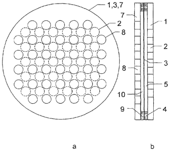
Fig. 3a and Fig. 3b show, analogously to Fig. 2a and Fig. 2b, the
substantially
modified elements of a capacitive sound transducer according to a first
embodiment of the invention. An additional attenuation disc 7 having
perforations
8 (unbroken lines) is disposed in front of diaphragm 3. The two sets of
perforations 2, 8 are offset in relation to each other in such a way that
there is
io nowhere where they overlap. A spacer 9 similar to spacer 4 determines the
distance between attenuation disc 7 and diaphragm 3, thus forming an second
air
gap 10. This results in diaphragm 3 being attenuated over its entire area by
an air
gap 5 and/or an air gap 10, that is to say, by at least one non-perforated
region.
In this way, the natural oscillations 6 of diaphragm 3 are efficaciously
suppressed.
In the embodiment shown in Fig. 3a and Fig. 3b, first perforations 2 and
second
perforations 8 are offset from each other in such a way that perforated
regions of
the counterelectrode 1 lie opposite non-perforated regions of the attenuation
disc
7. The perforated regions of attenuation disc 7 and of counterelectrode 1 are
of
the same size and shape, but different in number and arrangement in rows.
Figure 4 shows an example of a second embodiment according to the invention,
in which perforation set 8 of attenuation disc 7 partially overlaps
perforation set 2
of the counterelectrode 1 and in which perforation sets 2, 8 are arranged in
rows.
The first perforation set 2 and the second perforation set 8 are offset from
each
other in such a way that perforated regions of counterelectrode 1 each lie
opposite a part of a first perforated region of attenuation disc 7 and at
least one
part of a second perforated region of attenuation disc 7. In this case also,
efficacious attenuation of diaphragm 3 is achieved when the overlap is mainly
in
the edge regions of the perforations, with the result that sufficiently large
attenuating areas of counterelectrode 1 and attenuation disc 7, respectively,
CA 02622035 2011-07-29
- 14 -
particularly in the middle regions of the partial diaphragms, lie opposite the
diaphragm, also in the perforated regions of perforation sets 2 and 8.
Fig. 5 shows an example of a third possible embodiment with perforations
arranged rotationally symmetrically, in which perforation set 8 of attenuation
disc
7 and perforation set 2 of counterelectrode 1 overlap only slightly in the
edge
regions. The number of holes in counterelectrode 1 and in attenuation disc 7
is
the same in each of the three zones shown here by way of example, and the
acoustic effect of counterelectrode 1 and attenuation disc 7 is therefore
identical.
This embodiment is particularly suitable for realizing a symmetrical push-pull
1 o converter that combines the advantages of the attenuation disc of the
invention
and of a symmetrical push-pull converter.
In Figures 2 ¨ 5, the perforations are shown as circular holes of uniform
size, but
the perforations may be realized in any other shapes and sizes of perforated
regions. The perforations of the two discs may also be differently arranged
and/or
may differ from each other in number and shape.
The multi-rowed and circular arrangements of holes shown in the Figures
signify
examples only, and other arrangements of perforated regions may effect
equivalent attenuation of the natural oscillations of the diaphragm.
The attenuation disc of the invention can be disposed in a capacitive
recording
transducer as well as in a capacitive reproduction transducer. In both sound
transducers, an attenuation disc according to the invention acts to attenuate
and
reduce distortion, thus enhancing the signal quality.
Maximum attenuation of the partial vibrations is achieved when a perforated
region of the counterelectrode lies opposite a non-perforated region of the
attenuation disc. If the perforated regions of the counterelectrode and the
attenuation disc overlap, then although the attenuation effect of the partial
modes
is less, more perforated regions can be accommodated on the counterelectrode
and/or the attenuation disc, which leads to an increase in the sound
permeability
CA 02622035 2011-07-29
- 15 -
of the counterelectrode and/or the attenuation disc. This means that, for a
particular type of capacitive transducer, a compromise can be reached in the
number and arrangement of the perforations in relation to each other.